Downloads |
 Feedback Feedback
|
Table Of Contents
Optical Services Module Installation and Verification Note
Preventing Electrostatic Discharge Damage
Fiber Interface Specifications
Installing a GBIC with a Handle
Installing a GBIC with Plastic Clips
Removing a GBIC with Plastic Clips
Obtaining Documentation and Submitting a Service Request
Cisco Product Security Overview
Reporting Security Problems in Cisco Products
Obtaining Technical Assistance
Cisco Technical Support Website
Definitions of Service Request Severity
Obtaining Additional Publications and Information
Optical Services Module Installation and Verification Note
Product Numbers:
This publication provides procedures for installing and connecting Optical Services Modules (OSMs) in Cisco 7600 series routers and Catalyst 6500 series switches.
The OSMs are supported in the Cisco 7600 series routers and Catalyst 6500 series switches. The OSMs are supported with the following system configurations:
•
Supervisor Engine 2, Policy Feature Card 2 (PFC2), and Multilayer Switch Feature Card 2 (MSFC2)
•
•
•
•
Refer to the Release Notes for Cisco IOS Release 12.1 E on the Catalyst 6500 and Cisco 7600 MSFC, the Release Notes for Cisco IOS Release 12.1 E on the Catalyst 6000 and Cisco 7600 Supervisor Engine and MSFC, and the Release Notes for Cisco IOS Release 12.2 SX on the Catalyst 6500 and Cisco 7600 Supervisor Engine 720 publications for complete information about the chassis, modules, software features, protocols, and MIBs supported by the OSMs.
Note
Contents
This publication contains these sections:
•
•
•
•
•
•
Document Revision History
OL-5075-8
April, 2005
•
•
Overview
Table 1 describes the Cisco 7600 series router and Catalyst 6500 series chassis.
The OSMs are installed as follows:
•
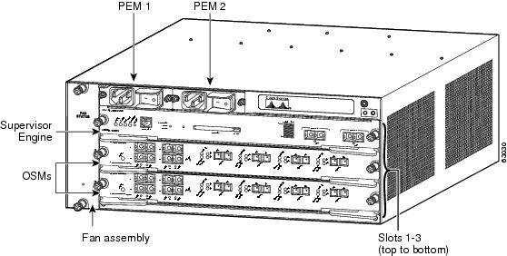
The slot numbering is the same in the 3-slot, 4-slot, 6-slot, and 13-slot chassis (see Figure 1).
•
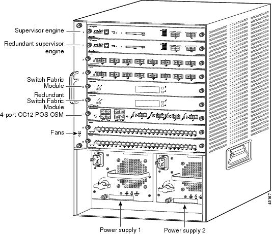
The slot numbering is the same in the 3-slot, 4-slot, 6-slot, 9-slot, and 13-slot chassis (see Figure 2).
•
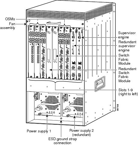
The horizontal slots are numbered from top to bottom; the vertical slots are numbered from right to left.
Figure 1 Slots on the Cisco 7603 Router
Figure 2 Slots on the Catalyst 6509 Switch
Note
Figure 3 Slots on the Cisco 7609 Router and Catalyst 6509-NEBS-A Switch
In all chassis, slot 1 is reserved for the supervisor engine. Slot 2 can contain an additional redundant supervisor engine in case the supervisor engine in slot 1 fails. If a redundant supervisor engine is not required, slot 2 is available for a module. Module filler plates, which are blank module carriers, are installed in empty slots to maintain consistent airflow through the chassis.
Optical Services Modules
Table 2 lists the OSMs that are described in this publication.
Table 2 Optical Services Modules
OSM-2OC12-POS-MM, -SI, -SL
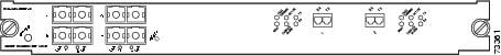
OSM-2OC12-POS-MM+, -SI+2-port OC-12 POS1 , plus 4 Gigabit Ethernet ports (requires GBICs2 ). The module has SC fiber connectors for use with MMF3 and SMF4 . See Figure 4.
OSM-4OC12-POS-MM, -SI, -SL
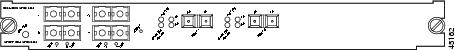
OSM-4OC12-POS-SI+4-port OC-12 POS, plus 4 Gigabit Ethernet ports (requires GBICs). The module has SC fiber connectors for use with MMF and SMF. See Figure 5.
OSM-4OC3-POS-SI
OSM-4OC3-POS-SI+4-port OC-3 POS, plus 4 Gigabit Ethernet ports (requires GBICs). The module has MT-RJ connectors for use with MMF and SMF. See Figure 6.
OSM-8OC3-POS-SI, -SL
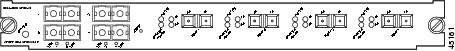
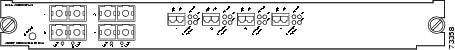
OSM-8OC3-POS-SI+, -SL+8-port OC-3 POS, plus 4 Gigabit Ethernet ports (requires GBICs). The module has MT-RJ connectors for use with MMF and SMF. See Figure 7.
OSM-1OC48-POS-SS, -SI, -SL
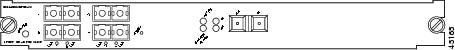
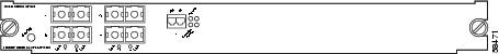
OSM-1OC48-POS-SS+, -SI+, -SL+1-port OC-48 POS, plus 4 Gigabit Ethernet ports (requires GBICs). The module has SC fiber connectors for use with SMF. See Figure 8.
OSM-2OC48/1DPT-SS, -SI, -SL
2-port OC-48 DPT5 /POS, plus 4 Gigabit Ethernet ports (requires GBICs). The module has LC fiber connectors for use with SMF. See Figure 9.
OSM-1CHOC12/T3-SI
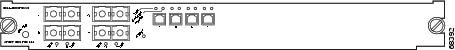
1-port channelized OC-12 T3, plus 4 Gigabit Ethernet ports (requires GBICs). The module has LC fiber connectors for use with SMF. See Figure 10.
OSM-4CHOC3/T1-SI6
4-port channelized OC-3, plus 4 Gigabit Ethernet ports (requires GBICs). The module has LC fiber connectors for use with SMF.See Figure 11
OSM-12CT3/DS0
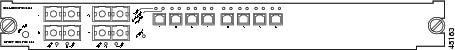
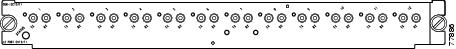
12-port channelized T3. The module has mini-SMB connectors for use with 75-ohm copper coaxial cable. See Figure 12.
OSM-1CHOC12/T1-SI
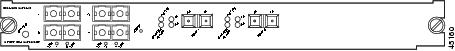
1-port channelized OC-12 T1, plus 4 Gigabit Ethernet ports (requires GBICs). The module has LC fiber connectors for use with SMF. See Figure 13.
OSM-2OC12-ATM-MM, SI
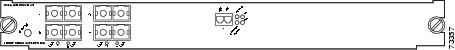
OSM-2OC12-ATM-MM+, SI+2-port OC-12 ATM6 , plus 4 Gigabit Ethernet ports (requires GBICs). The module has SC fiber connectors for use with MMF and SMF. See Figure 14.
OSM-2+4GE-WAN+
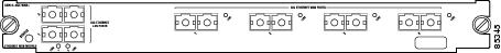
2-port Layer 2 Gigabit Ethernet LAN and 4-port Layer 3 Gigabit Ethernet WAN (all ports require GBICs). See Figure 15
1 POS = Packet over SONET.
2 GBICs = Gigabit Interface Converters; GBICs are available in three styles (SX, LX/LH, and ZX) and have an SC connector for use with either MMF or SMF.
3 MMF = multimode fiber.
4 SMF = single-mode fiber.
5 DPT = Dynamic Packet Transport.
6 ATM = Asynchronous Transfer Mode.
Figure 4 2-Port OC-12c POS OSM
Figure 5 4-Port OC-12c POS OSM
Figure 6 4-Port OC-3 POS OSM
Figure 7 8-Port OC-3 POS OSM
Figure 8 1-Port OC-48 POS OSM
Figure 9 2-Port OC-48 DPT/POS OSM
Figure 10 1-Port Channelized OC-12 T3 OSM
Figure 11 4-Port Channelized OC-3 OSM
Figure 12 12-Port Channelized T3 OSM
Figure 13 1-Port Channelized OC-12 T1 OSM
Figure 14 2-Port OC-12c ATM OSM
Figure 15 2-Port Gigabit Ethernet LAN and 4-Port Gigabit Ethernet WAN Services Module
Features
Note
http://www.cisco.com/univercd/cc/td/doc/product/core/cis7600/cfgnotes/osm_inst/index.htmThe OSM hardware features include:
•
•
Note
Note
•
The following connectors and transceivers are used by the OSMs:
•
–
–
–
•
–
–
–
•
–
–
–
•
–
–
–
•
•
•
–
–
•
–
–
–
Safety Overview
Safety warnings appear throughout this publication in procedures that, if performed incorrectly, may harm you. A warning symbol precedes each warning statement.
Warning
Warning
Warning
Warning
Warning
Warning
Warning
Required Tools
These tools are required to install an OSM in the Cisco 7600 series router or Catalyst 6500 series switch:
•
•
•
Whenever you handle an OSM, always use a wrist strap or other grounding device to prevent electrostatic discharge (ESD). For information on preventing ESD, see the "Preventing ESD" section of the Site Preparation and Safety Guide.
Preventing Electrostatic Discharge Damage
Electrostatic discharge (ESD) is a transfer of electrostatic charge between bodies of different electrostatic potentials, such as an operator and a piece of electrical equipment. It occurs when electronic components are improperly handled, and it can damage equipment and impair electrical circuitry. Electrostatic discharge is more likely to occur with the combination of synthetic fibers and dry atmosphere.
Step 1
Wear an ESD-preventive wrist strap that you provide, ensuring that it makes good skin contact.
Caution
Step 2
If cables are connected at one end only, do not touch the exposed pins at the unconnected end of the cable.
Note
Caution
Preparing to Install the OSMs
Warning
Before installing OSMs, you must install the Cisco 7600 series router or Catalyst 6500 series switch chassis and at least one supervisor engine.
For information on installing the chassis, refer to the Cisco 7603 and 7606 Router Installation Guide, the Cisco 7609 Router Installation Guide, or the Catalyst 6500 Series Installation Guide.
The OSMs are Class 1 laser products.
Warning
Installing the OSMs
This section describes how to install the OSMs in the Cisco 7600 series router and Catalyst 6500 series switches. Make sure that you have an open slot available for the new module.
Caution
Warning
Warning
Warning
To install an OSM in the Cisco 7600 series router or Catalyst 6500 series switch, perform these steps:
Step 1
Step 2
Step 3
Horizontal slots
a.
b.
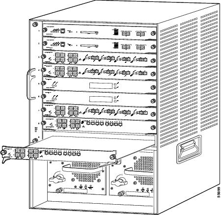
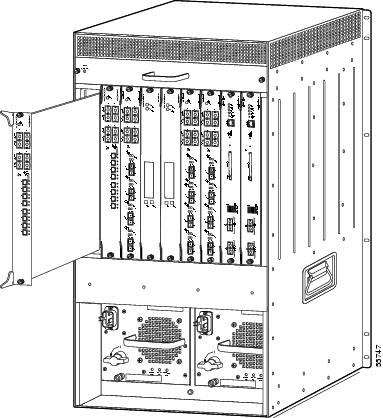
Figure 16 Chassis with Horizontal Slots
c.
Note
Vertical slots
a.
b.
Figure 17 Chassis with Vertical Slots
c.
Note
Step 4
Attaching Cables to the OSM
This section describes the following topics:
•
Warning
Connector Types
This section describes the types of connectors associated with the OSMs.
SC-Type Connector
Warning
The SC-type connector (see Figure 18) is used to connect the OSMs to optical networks using both multimode fiber (MMF) and single-mode fiber (SMF).
Figure 18 SC-Type Fiber-Optic Connector
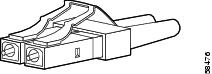
LC-Type Connector
Warning
The LC-type connector (see Figure 19) is used to connect the OC-48 DPT/POS, channelized OC-12, and OC-48 OSMs to optical networks using both MMF and SMF.
Figure 19 LC-Type Fiber-Optic Connector
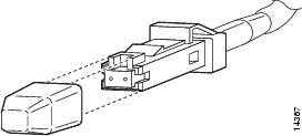
MT-RJ Connector
Warning
MT-RJ connectors provide a high-density optical connection between the OSM and the network. (See Figure 20.) When you are connecting MT-RJ cables to a module, make sure you firmly press the connector plug into the socket. The upper edge of the plug must snap into the upper front edge of the socket. You may hear an audible click. Gently pull on the plug to confirm whether or not the plug is locked into the socket.
Figure 20 MT-RJ Interface Cable Connector
Always make sure that you insert the connector completely into the socket. This step is especially important when you are making a connection between a module and a long distance (2 km) or a suspected highly attenuated network. If the link LED does not light, remove the network cable plug and reinsert it firmly into the module socket. Dirt or skin oils might have accumulated on the plug faceplate (around the optical-fiber openings) to generate significant attenuation, which reduces the optical power levels below threshold levels so that a link cannot be made.
Caution
To disconnect the plug from the socket, press down on the raised portion on top of the plug (releasing the latch). You should hear an audible click indicating the latch has released. Carefully pull the plug out of the socket.
To clean the MT-RJ plug faceplate:
Step 1
Step 2
Step 3
Note
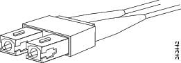
Mini-SMB Connector
The mini-SMB connector (see Figure 21) is used to connect the channelized DS3 OSMs to optical networks using RG-179 75-ohm copper coaxial cable.
Figure 21 Mini-SMB Cable Connector
The following cable options are available:
•
•
•
Fiber Interface Specifications
This section describes these topics:
OC-3, OC-12, and OC-48 POS
The specification for optical fiber transmission defines two types of fiber: single mode and multimode. Within the single-mode category, three transmission types are defined: short reach, intermediate reach, and long reach. Within the multimode category, only short reach is available.
Table 3 lists the specifications for OC-3, Table 4 lists the specifications for OC-12 OSM interfaces, and Table 5 lists the specifications for OC-48 OSM interfaces.
Gigabit Ethernet
Table 6 provides cabling specifications for the 1000BASE-X interfaces, including the Gigabit Ethernet GBIC interfaces. The minimum cable distance for all GBICs listed (MMF and SMF) is 6.5 feet (2 meters).
Table 6 Gigabit Ethernet Maximum Transmission Distances
SX2
850
MMF
62
62
50
50160
200
400
500722 ft (220 m)
902 ft (275 m)
1640 ft (500 m)
1804 ft (550 m)LX/LH
1300
MMF3
62
50
50500
400
5001804 ft (550 m)
1804 ft (550 m)
1804 ft (550 m)SMF (LX/LH)
9/104
-
6.2 mi (10 km)
ZX5
1550
SMF6
9/10
8-
-43.5 mi (70 km)7
62.1 mi (100 km)
1 Number listed is core size. The cladding size is usually 125 microns.
2 MMF only.
3 Patch cord required. (See the "Patch Cord" section for details.)
4 ANSI/TIA/EIA-568-A specifies that the nominal "mode field diameter" shall be 8.7 to 10.0 microns with a tolerance of +/- 0.5 microns at 1310 nm.
5 You can have a maximum of 24 1000BASE-ZX GBICs per system to comply with FCC Class A.
6 Dispersion-shifted single-mode fiber-optic cable.
7 The minimum link distance for ZX GBICs is 6.2 miles (10 km) with an 8-dB attenuator installed at each end of the link. Without attenuators, the minimum link distance is 24.9 miles (40 km).
Patch Cord
Warning
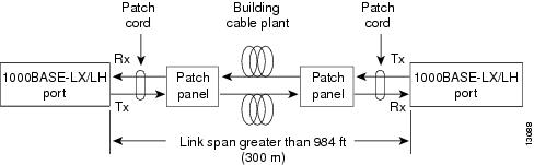
The mode-conditioning patch cord (Cisco product number CAB-GELX-625 or equivalent) prevents overdriving the receiver for short lengths of MMF and reduces differential mode delay for long lengths of MMF.
Note
Note
Figure 22 shows a typical configuration using the patch cord.
Figure 22 Patch Cord Configuration
Patch Cord Installation
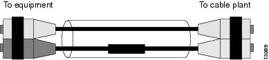
Plug the end of the patch cord labeled "To equipment" into the GBIC. (See Figure 23.) Plug the end labeled "To cable plant" into the patch panel. The patch cord is 9.84 feet (3 meters) long and has duplex SC-type male connectors at each end.
Figure 23 Patch Cord Installation
Differential Mode Delay
When an unconditioned laser source designed for operation on an SMF cable is directly coupled to an MMF cable, differential mode delay (DMD) might occur. DMD can degrade the modal bandwidth of the fiber-optic cable. This degradation causes a decrease in the link span (the distance between the transmitter and the receiver) that can be reliably supported.
The Gigabit Ethernet specification (IEEE 802.3z) outlines parameters for Ethernet communications at a gigabit-per-second rate. The specification offers a higher-speed version of Ethernet for backbone and server connectivity using existing deployed MMF cable by defining the use of laser-based optical components to propagate data over MMF cable.
Lasers function at the baud rates and longer distances required for Gigabit Ethernet. The 802.3z Gigabit Ethernet Task Force has identified the DMD condition that occurs with particular combinations of lasers and MMF cable. The results create an additional element of jitter that can limit the reach of Gigabit Ethernet over MMF cable.
With DMD, a single laser light pulse excites a few modes equally within an MMF cable. These modes, or light pathways, then follow two or more different paths. These paths might have different lengths and transmission delays as the light travels through the cable.
With DMD, a distinct pulse propagating down the cable no longer remains a distinct pulse or, in extreme cases, might become two independent pulses. Strings of pulses can interfere with each other making it difficult to recover data.
DMD does not occur in all deployed fibers; it occurs with certain combinations of worst-case fibers and worst-case transceivers. Gigabit Ethernet experiences this problem because of its very high baud rate and its long MMF cable lengths. SMF cable and copper cable are not affected by DMD.
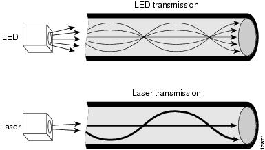
MMF cable has been tested for use only with LED sources. LEDs can create an overfilled launch condition within the fiber-optic cable. The overfilled launch condition describes the way LED transmitters couple light into the fiber-optic cable in a broad spread of modes. The generated light that shines in multiple directions can overfill the existing cable space and excite a large number of modes, similar to a light bulb radiating light into a dark room. (See Figure 24.)
Figure 24 LED Transmission Compared to Laser Transmission
Lasers launch light in a more concentrated fashion. A laser transmitter couples light into only a fraction of the existing modes or optical pathways present in the fiber-optic cable. (See Figure 24.)
The solution is to condition the laser light launched from the source (transmitter) so it spreads the light evenly across the diameter of the fiber-optic cable making the launch look more like an LED source to the cable. The objective is to scramble the modes of light to distribute the power more equally in all modes and prevent the light from being concentrated in just a few modes.
An unconditioned launch, in the worst case, might concentrate all of its light in the center of the fiber-optic cable, exciting only two or more modes equally.
A significant variation in the amount of DMD is produced from one MMF cable to the next. No reasonable test can be performed to survey an installed cable plant to assess the effect of DMD.
GBIC Installation
The GBIC is a hot-swappable input/output device that plugs into a Gigabit Ethernet port, linking the module port with the fiber-optic network.
GBIC Models
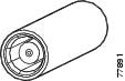
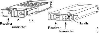
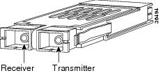
GBICs are available in the three optical models listed in Table 7. The three optical models differ in the distance that light can be sent through a fiber-optic network. These GBICs are available in the two physical models shown in Figure 25.
Table 7 GBIC Optical Models
Short wavelength (1000BASE-SX)
WS-G5484
Long wavelength/long haul (1000BASE-LX/LH)
WS-G5486
Extended distance (1000BASE-ZX)
WS-G5487
Figure 25 GBIC Physical Models
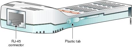
A copper GBIC, the WS-G5483, is available. The WS-G5483 provides 1000BASE-T full-duplex connectivity between the GBIC-compatible modules, supervisor engines, and the network up to a distance of 328 feet (100 m). See Figure 26.
Figure 26 Copper GBIC (WS-G5483)
Additionally, there are 32 fixed-wavelength GBICs that support the International Telecommunications Union (ITU) 100 GHz wavelength grid.The dense wavelength-division multiplexing (DWDM) GBICs are shown in Figure 27 and listed in Table 8.
Figure 27 DWDM and CWDM GBICs
Finally, there are eight coarse wavelength division multiplexing (CWDM) GBICs A set of eight CWDM GBICs are available for use with the CWDM Passive Optical System. The CWDM GBICs are shown in Figure 27 and listed in Table 9.
Note
When installing GBICs, do the following:
Warning
•
•
•
You can have a maximum of 24 1000BASE-ZX GBICs per system to comply with FCC Class A.
This section provides procedures for installing and removing a GBIC. For additional information on GBICs, refer to the Gigabit Interface Converter (GBIC) Module and Small Form-Factor Pluggable (SFP) GBIC Module Installation Information and Specifications.
Note
There are three locking mechanisms available to secure the GBIC in the module:
•
•
•
There are three methods of installation and removal; the one you use depends on your GBIC model.
•
•
•
•
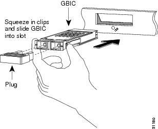
Installing a GBIC with Clips
Warning
To install a GBIC that has clips, perform these steps:
Step 1
Step 2
Step 3
Note
Figure 28 Installing a GBIC with Clips
Step 4
Step 5
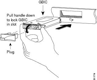
Installing a GBIC with a Handle
Warning
To install a GBIC that has a handle, perform these steps:
Step 1
Step 2
Step 3
Step 4
a.
b.
Step 5
Figure 29 Installing a GBIC with a Handle
Installing a GBIC with Plastic Clips
Warning
Caution
To install a GBIC with plastic clips, follow these steps:
Step 1
Step 2
Step 3
Step 4
Removing a GBIC with Clips
Warning
If you are removing a GBIC that has clips, perform these steps:
Step 1
Step 2
Step 3
A flap drops down to protect the Gigabit Ethernet module connector.
Step 4
Removing a GBIC with a Handle
Warning
If you are removing a GBIC with a handle, perform these steps:
Step 1
Step 2
Step 3
A flap drops down to protect the slot.
Step 4
Removing a GBIC with Plastic Clips
Warning
If you are removing a GBIC with plastic clips, perform these steps:
Step 1
Step 2
Step 3
Step 4
Warning
Verifying the Installation
Enter the show module command to verify that the system acknowledges the new modules and has brought them online.
This example shows the output of the show module command:
Router# show moduleMod Ports Card Type Model Serial No.--- ----- -------------------------------- ------------------ -----------1 2 Catalyst 6000 supervisor 2 (Active) WS-X6K-SUP2-2GE SAD04460M9T4 4 8-port CHOC-12/DS3 SI OSM-8CHOC12/T3-SI SAD0513000F5 0 Switching Fabric Module-128 (Active) WS-C6500-SFM SAD0445044Y6 0 Switching Fabric Module-128 (Standby) WS-C6500-SFM SAD044904RN7 4 2-port CHOC-48/DS3 SS OSM-2CHOC48/T3-SS SAD051409DW8 16 SFM-capable 16 port 1000mb GBIC WS-X6516-GBIC SAD04470AUK9 16 SFM-capable 16 port 1000mb GBIC WS-X6516-GBIC SAD044908JGMod MAC addresses Hw Fw Sw Status--- -------------------------------- ------ ------ ----- -------1 00d0.c0d4.0454 to 00d0.c0d4.0455 1.1 6.1(3) 6.2(0.116) Ok4 00d0.9738.a7e5 to 00d0.9738.a824 0.303 12.1(2001061 12.1(2001061 Ok5 0001.0002.0003 to 0001.0002.0003 1.0 6.1(3) 6.2(0.116) Ok6 0001.0002.0003 to 0001.0002.0003 1.0 6.1(3) 6.2(0.116) Ok7 00d0.9738.aa25 to 00d0.9738.aa64 0.202 12.1(2001061 12.1(2001061 Ok8 0001.c9d9.aa98 to 0001.c9d9.aaa7 2.0 6.1(3) 6.2(0.116) Ok9 00d0.c0d4.0e5c to 00d0.c0d4.0e6b 2.0 6.1(3) 6.2(0.116) OkMod Sub-Module Model Serial Hw Status--- ----------------------- --------------- ---------- ------- -------1 Policy Feature Card 2 WS-F6K-PFC2 SAD0443026F 1.0 Ok1 Cat6k MSFC 2 daughterboard WS-F6K-MSFC2 SAD04380K8K 1.1 OkRouter#Related Documentation
The following related publications are available:
•
•
•
•
•
•
•
•
•
•
•
For information about MIBs, refer to this url: http://www.cisco.com/public/sw-center/netmgmt/cmtk/mibs.shtml
Obtaining Documentation
Cisco documentation and additional literature are available on Cisco.com. Cisco also provides several ways to obtain technical assistance and other technical resources. These sections explain how to obtain technical information from Cisco Systems.
Cisco.com
You can access the most current Cisco documentation at this URL:
http://www.cisco.com/cisco/web/psa/default.html
You can access the Cisco website at this URL:
You can access international Cisco websites at this URL:
http://www.cisco.com/web/siteassets/locator/index.html
Documentation DVD
Cisco documentation and additional literature are available in a Documentation DVD package, which may have shipped with your product. The Documentation DVD is updated regularly and may be more current than printed documentation. The Documentation DVD package is available as a single unit.
Registered Cisco.com users (Cisco direct customers) can order a Cisco Documentation DVD (product number DOC-DOCDVD=) from the Ordering tool or Cisco Marketplace.
Cisco Ordering tool:
http://www.cisco.com/en/US/partner/ordering/
Cisco Marketplace:
http://www.cisco.com/go/marketplace/
Ordering Documentation
You can find instructions for ordering documentation at this URL:
http://www.cisco.com/en/US/docs/general/Illus_process/PDI/pdi.htm
You can order Cisco documentation in these ways:
•
http://www.cisco.com/en/US/partner/ordering/
•
Obtaining Documentation and Submitting a Service Request
For information on obtaining documentation, submitting a service request, and gathering additional information, see the monthly What's New in Cisco Product Documentation, which also lists all new and revised Cisco technical documentation, at:
http://www.cisco.com/en/US/docs/general/whatsnew/whatsnew.html
Subscribe to the What's New in Cisco Product Documentation as a Really Simple Syndication (RSS) feed and set content to be delivered directly to your desktop using a reader application. The RSS feeds are a free service and Cisco currently supports RSS Version 2.0.
Cisco Product Security Overview
Cisco provides a free online Security Vulnerability Policy portal at this URL:
http://www.cisco.com/en/US/products/products_security_vulnerability_policy.html
From this site, you can perform these tasks:
•
•
•
A current list of security advisories and notices for Cisco products is available at this URL:
If you prefer to see advisories and notices as they are updated in real time, you can access a Product Security Incident Response Team Really Simple Syndication (PSIRT RSS) feed from this URL:
http://www.cisco.com/en/US/products/products_psirt_rss_feed.html
Reporting Security Problems in Cisco Products
Cisco is committed to delivering secure products. We test our products internally before we release them, and we strive to correct all vulnerabilities quickly. If you think that you might have identified a vulnerability in a Cisco product, contact PSIRT:
•
•
Tip
Never use a revoked or an expired encryption key. The correct public key to use in your correspondence with PSIRT is the one that has the most recent creation date in this public key server list:
http://pgp.mit.edu:11371/pks/lookup?search=psirt%40cisco.com&op=index&exact=on
In an emergency, you can also reach PSIRT by telephone:
•
•
Obtaining Technical Assistance
For all customers, partners, resellers, and distributors who hold valid Cisco service contracts, Cisco Technical Support provides 24-hour-a-day, award-winning technical assistance. The Cisco Technical Support Website on Cisco.com features extensive online support resources. In addition, Cisco Technical Assistance Center (TAC) engineers provide telephone support. If you do not hold a valid Cisco service contract, contact your reseller.
Cisco Technical Support Website
The Cisco Technical Support Website provides online documents and tools for troubleshooting and resolving technical issues with Cisco products and technologies. The website is available 24 hours a day, 365 days a year, at this URL:
http://www.cisco.com/cisco/web/support/index.html
Access to all tools on the Cisco Technical Support Website requires a Cisco.com user ID and password. If you have a valid service contract but do not have a user ID or password, you can register at this URL:
http://tools.cisco.com/RPF/register/register.do
Note
Submitting a Service Request
Using the online TAC Service Request Tool is the fastest way to open S3 and S4 service requests. (S3 and S4 service requests are those in which your network is minimally impaired or for which you require product information.) After you describe your situation, the TAC Service Request Tool provides recommended solutions. If your issue is not resolved using the recommended resources, your service request is assigned to a Cisco TAC engineer. The TAC Service Request Tool is located at this URL:
http://www.cisco.com/techsupport/servicerequest
For S1 or S2 service requests or if you do not have Internet access, contact the Cisco TAC by telephone. (S1 or S2 service requests are those in which your production network is down or severely degraded.) Cisco TAC engineers are assigned immediately to S1 and S2 service requests to help keep your business operations running smoothly.
To open a service request by telephone, use one of the following numbers:
Asia-Pacific: +61 2 8446 7411 (Australia: 1 800 805 227)
EMEA: +32 2 704 55 55
USA: 1 800 553-2447For a complete list of Cisco TAC contacts, go to this URL:
http://www.cisco.com/en/US/support/tsd_contact_technical_support.html
Definitions of Service Request Severity
To ensure that all service requests are reported in a standard format, Cisco has established severity definitions.
Severity 1 (S1)—Your network is "down," or there is a critical impact to your business operations. You and Cisco will commit all necessary resources around the clock to resolve the situation.
Severity 2 (S2)—Operation of an existing network is severely degraded, or significant aspects of your business operation are negatively affected by inadequate performance of Cisco products. You and Cisco will commit full-time resources during normal business hours to resolve the situation.
Severity 3 (S3)—Operational performance of your network is impaired, but most business operations remain functional. You and Cisco will commit resources during normal business hours to restore service to satisfactory levels.
Severity 4 (S4)—You require information or assistance with Cisco product capabilities, installation, or configuration. There is little or no effect on your business operations.
Obtaining Additional Publications and Information
Information about Cisco products, technologies, and network solutions is available from various online and printed sources.
•
http://www.cisco.com/go/marketplace/
•
•
http://www.cisco.com/web/about/ac123/ac114/about_cisco_packet_magazine.html
•
http://www.cisco.com/web/about/ac123/ac147/about_cisco_the_internet_protocol_journal.html
•
http://www.cisco.com/web/learning/index.html
This document is to be used in conjunction with the documents listed in the "Related Documentation" section.
CCSP, the Cisco Square Bridge logo, Follow Me Browsing, and StackWise are trademarks of Cisco Systems, Inc.; Changing the Way We Work, Live, Play, and Learn, and iQuick Study are service marks of Cisco Systems, Inc.; and Access Registrar, Aironet, ASIST, BPX, Catalyst, CCDA, CCDP, CCIE, CCIP, CCNA, CCNP, Cisco, the Cisco Certified Internetwork Expert logo, Cisco IOS, Cisco Press, Cisco Systems, Cisco Systems Capital, the Cisco Systems logo, Cisco Unity, Empowering the Internet Generation, Enterprise/Solver, EtherChannel, EtherFast, EtherSwitch, Fast Step, FormShare, GigaDrive, GigaStack, HomeLink, Internet Quotient, IOS, IP/TV, iQ Expertise, the iQ logo, iQ Net Readiness Scorecard, LightStream, Linksys, MeetingPlace, MGX, the Networkers logo, Networking Academy, Network Registrar, Packet, PIX, Post-Routing, Pre-Routing, ProConnect, RateMUX, ScriptShare, SlideCast, SMARTnet, StrataView Plus, SwitchProbe, TeleRouter, The Fastest Way to Increase Your Internet Quotient, TransPath, and VCO are registered trademarks of Cisco Systems, Inc. and/or its affiliates in the United States and certain other countries.
All other trademarks mentioned in this document or Website are the property of their respective owners. The use of the word partner does not imply a partnership relationship between Cisco and any other company. (0501R)
)