Cisco WDM Series Passive Optical System Installation Note
Available Languages
Table Of Contents
Cisco CWDM Passive Optical System Installation Note
8-Channel Multiplexer/Demultiplexer (CWDM-MUX-8A=)
4-Channel OADM (CWDM-OADM4-1= and CWDM-OADM4-2=)
Dual Single-Channel OADMs (CWDM-OADM1-xxxx)
WDM Splitter Cable (WDM-1300-1550-S=)
CWDM GBIC and CWDM SFP Transceivers
Statement 1071—Warning Definition
Installing the CWDM Passive Optical System
Installing the 2-Slot Chassis (CWDM-CHASSIS-2=)
Installing the CWDM OADM Modules
Installing and Removing CWDM GBIC and CWDM SFP Transceivers
Connecting the CWDM Passive Optical System to Your System
Connecting Cables to the Dual Single-Channel OADM Module
Connecting Cables to the CWDM 4-Channel OADM Module
Connecting Cables to the CWDM 8-Channel Multiplexer/Demultiplexer Module
Statement 1030—Equipment Installation
Statement 1040—Product Disposal
Statement 1053—Class 1M Laser Radiation
Statement 1055—Class I and Class 1M Laser
Statement 1056—Unterminated Fiber Cable
Statement 1057—Hazardous Radiation Exposure
Obtaining Documentation and Submitting a Service Request
Cisco CWDM Passive Optical System Installation Note
This document provides installation instructions for the Cisco Coarse Wave Division Multiplexer (CWDM) passive optical system. The CWDM passive optical system product numbers are listed in Table 1.
Contents
This installation note contains the following sections:
•
Installing the CWDM Passive Optical System
•
•
Overview
The Cisco CWDM passive optical system provides optical networking support for high-speed data communication for metropolitan area networks (MANs) over a grid of eight CWDM optical wavelengths in both ring configurations or point-to-point configurations.
The Cisco CWDM passive optical system includes these components:
•
•
–
–
–
•
•
CWDM 2-Slot Chassis
The CWDM 2-slot chassis (CWDM-CHASSIS-2) is a standard 19-inch chassis that is one rack unit (RU) in height. Each CWDM 2-slot chassis can hold two CWDM OADM modules. You can install the CWDM 2-slot chassis in the same equipment rack as your system or in an adjacent rack so that you can connect the OADMs to the CWDM GBIC transceivers or the CWDM SFP transceivers.
CWDM OADMs
The CWDM OADMs are passive devices that can multiplex/demultiplex or add/drop wavelengths from multiple fibers onto one optical fiber. The OADM connectors are interfaced to the color-matching CWDM GBIC or CWDM SFP transceivers on the equipment side. All OADMs are the same size. Two OADM modules can be installed in a CWDM 2-slot chassis (CWDM-CHASSIS-2). There are three different types of CWDM OADM modules
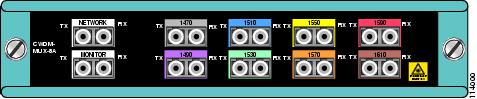
8-Channel Multiplexer/Demultiplexer (CWDM-MUX-8A=)
The 8-Channel Multiplexer/Demultiplexer (CWDM-MUX-8A=) allows you to multiplex/demultiplex eight separate channels into one pair of fiber. Dual fiber is used for both the network connection and the CWDM GBIC or CWDM SFP transceiver connections. The eight available wavelengths are 1470-nm, 1490-nm, 1510-nm, 1530-nm, 1550-nm, 1570-nm, 1590-nm, and 1610-nm. The multiplexer/demultiplexer, shown in Figure 1, is equipped with a monitor port that allows you to attach a power meter or an optical spectrum analyzer to assist you in monitoring and troubleshooting the network.
Figure 1 8-Channel Multiplexer/Demultiplexer (CWDM-MUX8) Front Panel
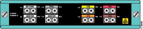
4-Channel OADM (CWDM-OADM4-1= and CWDM-OADM4-2=)
The 4-Channel OADM (CWDM-OADM4-1= and CWDM-OADM4-2=) allows you to add/drop four channels (with different wavelengths) into one direction of an optical ring. The other wavelengths are passed through the OADM. The 4-channel OADMs are transparent to the 1300-nm wavelength and includes a 1300-nm/1500-nm filter to mix legacy SONET/SDH/ATM ring installations with CWDM installations on the same optical fiber. Dual fiber is used for both the network and the GBIC or SFP connections. The two 4-channel OADMs, shown in Figure 2 and Figure 3, support the following wavelengths:
•
•
The 4-channel OADM modules are equipped with a monitor port that allows you to attach a power meter or an optical spectrum analyzer to assist you in monitoring and troubleshooting the network.
Figure 2 4-Channel OADM (CWDM-OADM4-1) Front Panel
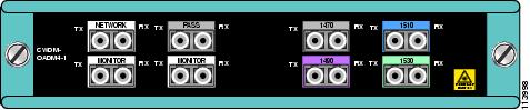
Figure 3 4-Channel OADM (CWDM-OADM4-2) Front Panel
Dual Single-Channel OADMs (CWDM-OADM1-xxxx)
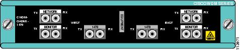
The Dual Single-Channel OADMs (CWDM-OADM1-xxxx) allows you to add/drop two channels of the same wavelength into the two directions of an optical ring. The other wavelengths are passed through the OADM. The dual single-channel OADMs are transparent to the 1300-nm wavelength and includes a 1300-nm/1500-nm filter to mix legacy SONET/SDH/ATM ring installations with CWDM installations on the same optical fiber. Dual fiber is used for both the network and the CWDM GBIC and CWDM SFP connections. Eight versions of this OADM are available, one for each wavelength of light. (See Table 2.) The dual single-channel OADMs, shown in Figures 4 through 11, are color coded and match the color coding of the CWDM GBIC and CWDM SFP transceivers. The dual single-channel OADM modules are equipped with a monitor port that allows you to attach a power meter or an optical spectrum analyzer to assist you in monitoring and troubleshooting the network.
Table 3 provides a comparison of the CWDM passive device types.
The OADM module ports are color coded to help with installation. Each color indicates the wavelength of the port. For more information about the color codes, see the "Connecting the CWDM Passive Optical System to Your System" section.
Figure 4 Dual Single-Channel OADM Front Panel (1610 nm)
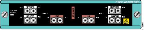
Figure 5 Dual Single-Channel OADM Front Panel (1590 nm)
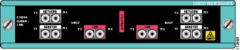
Figure 6 Dual Single-Channel OADM Front Panel (1570 nm)
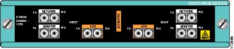
Figure 7 Dual Single-Channel OADM Front Panel (1550 nm)
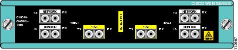
Figure 8 Dual Single-Channel OADM Front Panel (1530 nm)
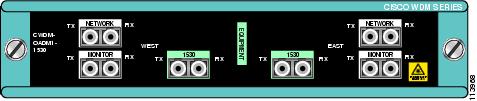
Figure 9 Dual Single-Channel OADM Front Panel (1510 nm)
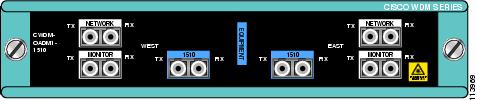
Figure 10 Dual Single-Channel OADM Front Panel (1490 nm)
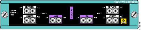
Figure 11 Dual Single-Channel OADM Front Panel (1470 nm)
WDM Splitter Cable (WDM-1300-1550-S=)
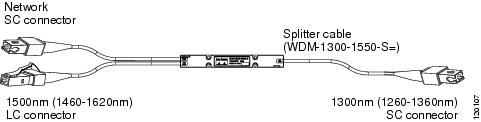
The WDM splitter cable provides bidirectional, multiplexing/demultiplexing for 1310-nm and 1550-nm signals. The WDM splitter cable is a Y cable (see Figure 12) with a 1310-nm branch terminating in an SC connector and a 1550-nm branch terminating in an LC connector. The common trunk branch of the Y cable is terminated in an SC connector. The WDM splitter cable is 1 meter in length.
Figure 12 WDM Splitter Cable
CWDM GBIC and CWDM SFP Transceivers
The CWDM GBIC and CWDM SFP transceivers are hot-swappable input/output devices that link your switching module to the CWDM passive optical system using a pair of single-mode fiber-optic cables. The two transceiver types have different form factors and use different fiber-optic cable connectors. Figure 13 shows a CWDM GBIC transceiver which uses an SC connector, and Figure 14 shows a CWDM SFP transceiver which uses an LC connector.
Figure 13 CWDM GBIC
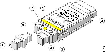
Color label identifying laser wavelength
Optical bore dust plug
Alignment groove
Receive optical bore
Spring clip
Color dot identifying laser wavelength
Transmit optical bore

Warning
Figure 14 CWDM SFP
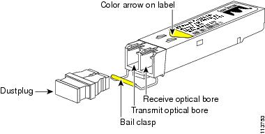
The CWDM GBIC and CWDM SFP transceivers are available in eight wavelengths. (See Table 4.) Each CWDM GBIC and CWDM SFP transceiver is color coded to match the connector colors on the OADM modules.
For information on installing, removing, and maintaining the CWDM GBIC and SFP transceivers, refer to the Cisco CWDM GBIC and CWDM SFP Installation Note that accompanies the CWDM GBIC and CWDM SFP transceivers.
Safety Overview
Throughout this publication, safety warnings appear in procedures that, if performed incorrectly, can harm you. A warning symbol precedes each warning statement.
Statement 1071—Warning Definition
Warning
Warning
Warning
Warning

Note
Installing the CWDM Passive Optical System
The following sections provide installation procedures for the CWDM passive optical system components:
•
•
•
•
Required Tools
You will need these tools to install the CWDM passive optical system:
•
•
•
•
http://www.cisco.com/en/US/tech/tk482/tk607/technologies_white_paper09186a0080254eba.shtml
•
•
Installing the 2-Slot Chassis (CWDM-CHASSIS-2=)
Note

Caution
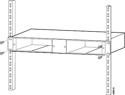
To mount the 2-slot chassis in an equipment rack, follow these steps:
Step 1
Step 2
Step 3
Figure 15 Mounting the 2-Slot Chassis in the Rack
Installing the CWDM OADM Modules
Caution
To install the CWDM OADM modules, follow these steps:
Step 1
Figure 16 Installing a CWDM OADM Module
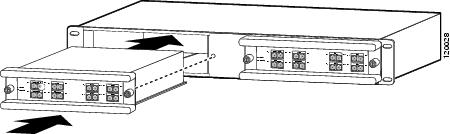
Step 2
Step 3
Step 4
Removing the CWDM OADM Module
Caution
To remove the OADM module or the multiplexer/demultiplexer module, follow these steps:
Step 1
Step 2
Step 3
Step 4
Installing and Removing CWDM GBIC and CWDM SFP Transceivers
For information on installing, removing, and maintaining the CWDM GBIC transceivers and CWDM SFP transceivers, refer to the Cisco CWDM GBIC and CWDM SFP Installation Note that accompanies the CWDM GBIC and CWDM SFP transceivers.
Caution
Note
Connecting the CWDM Passive Optical System to Your System
This section is divided into the following topics:
•
•
•
Note
See Figure 2 through Figure 13 for the OADM and multiplexer/demultiplexer module front panels.
Warning
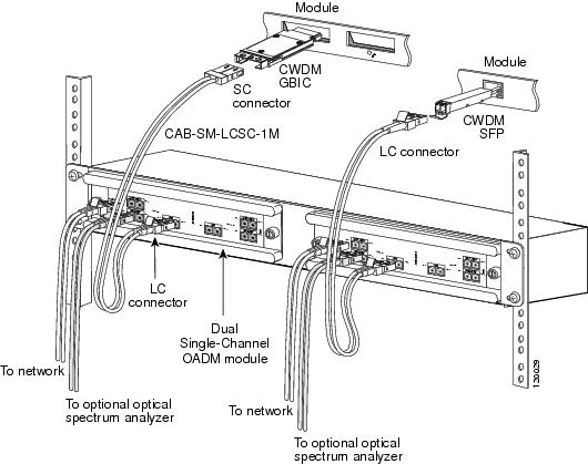
Connecting Cables to the Dual Single-Channel OADM Module
Note
To connect the cables to the dual single-channel OADM module, follow these steps (see Figure 17):
Step 1
Note
Note
Warning
Figure 17 Cabling a CWDM Dual Single-Channel OADM Module
Note
•
•
•
Step 2
Step 3

Tip
http://www.cisco.com/en/US/tech/tk482/tk607/technologies_white_paper09186a0080254eba.shtml
Step 4
a.
b.
Note
Step 5
Step 6
Step 7
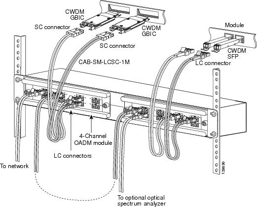
Connecting Cables to the CWDM 4-Channel OADM Module
Note
To connect the cables to the CWDM 4-channel OADM module, follow these steps (see Figure 18):
Step 1
Note
Note
Warning
Figure 18 Cabling a 4-Channel OADM Module
Note
•
•
•
Step 2
Step 3
Tip
http://www.cisco.com/en/US/tech/tk482/tk607/technologies_white_paper09186a0080254eba.shtml
Step 4
Note
Step 5
Step 6
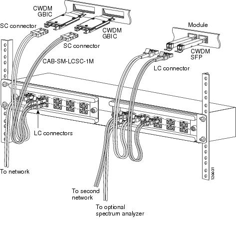
Connecting Cables to the CWDM 8-Channel Multiplexer/Demultiplexer Module
Note
To connect cables to a CWDM 8-channel multiplexer/demultiplexer module, follow these steps (see Figure 19):
Step 1
Note
Note
Warning
Figure 19 Cabling a CWDM 8-Channel Multiplexer/Demultiplexer Module
Note
•
•
•
Step 2
Step 3
Tip
http://www.cisco.com/en/US/tech/tk482/tk607/technologies_white_paper09186a0080254eba.shtml
Step 4
Note
Note
Step 5
Step 6
Specifications
Table 5 lists the environmental specifications for the CWDM OADM and multiplexer/demultiplexer modules. Table 6 lists the optical specifications for the CWDM OADM and multiplexer/demultiplexer modules.
Translated Safety Warnings
This section contains the translations to the warnings that appear in this publication.
Statement 1030—Equipment Installation
Statement 1040—Product Disposal
Statement 1053—Class 1M Laser Radiation
Statement 1055—Class I and Class 1M Laser
Statement 1056—Unterminated Fiber Cable
Statement 1057—Hazardous Radiation Exposure
Obtaining Documentation and Submitting a Service Request
For information on obtaining documentation, submitting a service request, and gathering additional information, see the monthly What's New in Cisco Product Documentation, which also lists all new and revised Cisco technical documentation, at:
http://www.cisco.com/en/US/docs/general/whatsnew/whatsnew.html
Subscribe to the What's New in Cisco Product Documentation as a Really Simple Syndication (RSS) feed and set content to be delivered directly to your desktop using a reader application. The RSS feeds are a free service and Cisco currently supports RSS Version 2.0.


 Feedback
Contact Cisco
- Open a Support Case

- (Requires a Cisco Service Contract)