Downloads |
 Feedback Feedback
|
Table Of Contents
5.2.2 E100T-12 Card-Level Indicators
5.2.3 E100T-12 Port-Level Indicators
5.2.5 E100T-12 Card Specifications
5.3.2 E100T-G Card-Level Indicators
5.3.3 E100T-G Port-Level Indicators
5.3.4 E100T-G Card Specifications
5.4.2 E1000-2 Card-Level Indicators
5.4.3 E1000-2 Port-Level Indicators
5.4.5 E1000-2 Card Specifications
5.5.2 E1000-2-G Card-Level Indicators
5.5.3 E1000-2-G Port-Level Indicators
5.5.4 E1000-2-G Card Specifications
5.6.1 G1000-4 Card-Level Indicators
5.6.2 G1000-4 Port-Level Indicators
5.6.4 G1000-4 Card Specifications
5.7.2 G1K-4 Card-Level Indicators
5.7.3 G1K-4 Port-Level Indicators
5.7.4 G1K-4 Card Specifications
5.8.1 ML100T-12 Card-Level Indicators
5.8.2 ML100T-12 Port-Level Indicators
5.8.4 ML100T-12 Card Specifications
5.9.1 ML1000-2 Card-Level Indicators
5.9.2 ML1000-2 Port-Level Indicators
5.9.4 ML1000-2 Card Specifications
5.10.1 Small Form-Factor Pluggable Connectors (SFPs)
5.10.2 Ethernet Gigabit Interface Converters (GBICs)
Ethernet Cards
Note
The terms "Unidirectional Path Switched Ring" and "UPSR" may appear in Cisco literature. These terms do not refer to using Cisco ONS 15xxx products in a unidirectional path switched ring configuration. Rather, these terms, as well as "Path Protected Mesh Network" and "PPMN," refer generally to Cisco's path protection feature, which may be used in any topological network configuration. Cisco does not recommend using its path protection feature in any particular topological network configuration.
The Cisco ONS 15454 integrates Ethernet into a SONET platform through the use of Ethernet cards. This chapter describes the E-Series, G-Series, and ML-Series Ethernet cards. For G-Series and E-Series Ethernet application information, see "Ethernet Operation." For installation and card turn-up procedures, refer to the Cisco ONS 15454 Procedure Guide. For ML-Series configuration information, see the Cisco ONS 15454 SONET/SDH ML-Series Multilayer Ethernet Card Software Feature and Configuration Guide.
Chapter topics include:
5.1 Card Overview
The card overview section summarizes card functions, power consumption and temperature ranges.
Note
5.1.1 Ethernet Cards
Table 5-1 lists the Cisco ONS 15454 Ethernet cards.
Table 5-1 Ethernet Cards for the ONS 15454
E100T-12
The E100T-12 card provides 12 switched, autosensing, 10/100BaseT Ethernet ports.
See the "E100T-12 Card" section.
E1000-2
The E1000-2 card provides two IEEE-compliant, 1000-Mbps ports. GBICs are separate.
See the "E1000-2 Card" section.
E100T-G
The E100T-G card provides 12 switched, autosensing, 10/100BaseT Ethernet ports and is compatible with the XC10G card.
See the "E100T-G Card" section.
E1000-2-G
The E1000-2-G card provides two IEEE-compliant, 1000-Mbps ports. GBICs are separate. The E1000-2-G card is compatible with the XC10G card.
See the "E1000-2-G Card" section.
G1000-4
The G1000-4 card provides four IEEE-compliant, 1000-Mbps ports. GBICs are separate. The G1000-4 requires the XC10G card.
See the "G1000-4 Card" section.
G1K-4
The G1K-4 card provides four IEEE-compliant, 1000-Mbps ports. GBICs are separate. The G1K-4 card is functionally identical to the G1000-4 card, but can operate with XC, XCVT or XC10G cross-connect cards.
See the "G1K-4 Card" section.
ML100T-12
The ML100T-12 card provides 12 switched, autosensing, 10/100Base-T Ethernet ports.
See the "ML100T-12 Card" section.
ML1000-2
The ML1000-2 card provides two IEEE-compliant, 1000-Mbps ports. Small form-factor pluggable (SFP) connectors are separate.
See the "ML1000-2 Card" section.
5.1.2 Card Power Requirements
Table 5-2 lists power requirements for individual cards.
5.1.3 Card Temperature Ranges
Table 5-3 shows C-Temp and I-Temp compliant cards and their product names.
Note
5.2 E100T-12 Card
The ONS 15454 uses E100T-12 cards for Ethernet (10 Mbps) and Fast Ethernet (100 Mbps). Each card provides 12 switched, IEEE 802.3-compliant, 10/100BaseT Ethernet ports that can independently detect the speed of an attached device (autosense) and automatically connect at the appropriate speed. The ports autoconfigure to operate at either half or full duplex and determine whether to enable or disable flow control. You can also configure Ethernet ports manually. Figure 5-1 shows the faceplate and a block diagram of the card.
Figure 5-1 E100T-12 Faceplate and Block Diagram
The E100T-12 Ethernet card provides high-throughput, low-latency packet switching of Ethernet traffic across a SONET network while providing a greater degree of reliability through SONET "self-healing" protection services. This Ethernet capability enables network operators to provide multiple 10/100-Mbps access drops for high-capacity customer LAN interconnects, Internet traffic, and cable modem traffic aggregation. It enables the efficient transport and co-existence of traditional TDM traffic with packet-switched data traffic.
Each E100T-12 card supports standards-based, wire-speed, Layer 2 Ethernet switching between its Ethernet interfaces. The IEEE 802.1Q tag logically isolates traffic (typically subscribers). IEEE 802.1Q also supports multiple classes of service.
5.2.1 Slot Compatibility
You can install the E100T-12 card in any multi-speed or high-speed slot (Slots 1 to 6 and 12 to 17). Multiple Ethernet cards installed in an ONS 15454 can act independently or as a single Ethernet switch. You can create logical SONET ports by provisioning STS channels to the packet switch entity within the ONS 15454. Logical ports can be created with a bandwidth granularity of STS-1. The E100T-12 supports STS-1, STS-3c, STS-6c, and STS-12c circuit sizes.
Note
5.2.2 E100T-12 Card-Level Indicators
The E100T-12 card faceplate has two card-level LED indicators. (See Table 5-4.)
5.2.3 E100T-12 Port-Level Indicators
The E100T-12 card has 12 pairs of LEDs (one pair for each port) to indicate port conditions. (See Table 5-5.) You can find the status of the E100T-12 card port using the LCD on the ONS 15454 fan-tray assembly. Use the LCD to view the status of any port or card slot; the screen displays the number and severity of alarms for a given port or slot.
5.2.4 E100T-12 Compatibility
Do not use the E100T-12 card with the XC10G card. The E100T-G is compatible with the XC10G.
5.2.5 E100T-12 Card Specifications
The E100T-12 card has the following specifications:
•
–
C-Temp (15454-E100T): 0 to +55 degrees Celsius
–
–
•
–
–
–
–
•
–
5.3 E100T-G Card
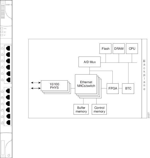
Use the E100T-G card when the XC10G card is in use. The ONS 15454 uses E100T-G cards for Ethernet (10 Mbps) and Fast Ethernet (100 Mbps). Each card provides 12 switched, IEEE 802.3-compliant, 10/100BaseT Ethernet ports that can independently detect the speed of an attached device (autosense) and automatically connect at the appropriate speed. The ports auto-configure to operate at either half or full duplex and determine whether to enable or disable flow control. You can also configure Ethernet ports manually. Figure 5-2 shows the faceplate and a block diagram of the card.
Figure 5-2 E100T-G Faceplate and Block Diagram
The E100T-G Ethernet card provides high-throughput, low-latency packet switching of Ethernet traffic across a SONET network while providing a greater degree of reliability through SONET "self-healing" protection services. This Ethernet capability enables network operators to provide multiple 10/100 Mbps access drops for high-capacity customer LAN interconnects, Internet traffic, and cable modem traffic aggregation. It enables the efficient transport and co-existence of traditional TDM traffic with packet-switched data traffic.
Each E100T-G card supports standards-based, wire-speed, Layer 2 Ethernet switching between its Ethernet interfaces. The IEEE 802.1Q tag logically isolates traffic (typically subscribers). IEEE 802.1Q also supports multiple classes of service.
Note
5.3.1 Slot Compatibility
You can install the E100T-G card in any multi-speed or high-speed slot, (Slots 1 to 6 and 12 to 17). Multiple Ethernet cards installed in an ONS 15454 can act independently or as a single Ethernet switch. You can create logical SONET ports by provisioning a number of STS channels to the packet switch entity within the ONS 15454. Logical ports can be created with a bandwidth granularity of STS-1. The ONS 15454 supports STS-1, STS-3c, STS-6c, or STS-12c circuit sizes.
5.3.2 E100T-G Card-Level Indicators
The E100T-G card faceplate has two card-level LED indicators. (see Table 5-6.)
5.3.3 E100T-G Port-Level Indicators
The E100T-G card also has 12 pairs of LEDs (one pair for each port) to indicate port conditions. (See Table 5-7.) You can find the status of the E100T-G card port using the LCD screen on the ONS 15454 fan-tray assembly. Use the LCD to view the status of any port or card slot; the screen displays the number and severity of alarms for a given port or slot.
5.3.4 E100T-G Card Specifications
The E100T-G card has the following specifications:
•
–
C-Temp (15454-E100T-G): 0 to +55 degrees Celsius
–
–
•
–
–
–
–
•
–
5.4 E1000-2 Card
The ONS 15454 uses E1000-2 cards for Gigabit Ethernet (1000 Mbps). The E1000-2 card provides two IEEE-compliant, 1000-Mbps ports for high-capacity customer LAN interconnections. Each port supports full-duplex operation.
The E1000-2 card uses GBIC modular receptacles for the optical interfaces. For details, see the "Ethernet Gigabit Interface Converters (GBICs)" section.
Figure 5-3 shows the card faceplate and a block diagram of the card.
Figure 5-3 E1000-2 Faceplate and Block Diagram
The E1000-2 Gigabit Ethernet card provides high-throughput, low-latency packet switching of Ethernet traffic across a SONET network while providing a greater degree of reliability through SONET "self-healing" protection services. This enables network operators to provide multiple 1000-Mbps access drops for high-capacity customer LAN interconnects. It enables efficient transport and co-existence of traditional TDM traffic with packet-switched data traffic.
Each E1000-2 card supports standards-based, Layer 2 Ethernet switching between its Ethernet interfaces and SONET interfaces on the ONS 15454. The IEEE 802.1Q VLAN tag logically isolates traffic (typically subscribers).
Multiple Ethernet cards installed in an ONS 15454 can act together as a single switching entity or as an independent single switch supporting a variety of SONET port configurations.
You can create logical SONET ports by provisioning STS channels to the packet switch entity within the ONS 15454. Logical ports can be created with a bandwidth granularity of STS-1. The ONS 15454 supports STS-1, STS-3c, STS-6c, or STS-12c circuit sizes.
Note
5.4.1 Slot Compatibility
You can install the E1000-2 card in any multi-speed or high-speed card slots, (Slots 1 to 6 and 12 to 17). The E1000-2 is compatible with the XC or XCVT cross-connect cards, but not the XC10G. The E1000-2-G is compatible with the XC10G.
5.4.2 E1000-2 Card-Level Indicators
The E1000-2 card faceplate has two card-level LED indicators (Table 5-8).
5.4.3 E1000-2 Port-Level Indicators
The E1000-2 card also has one bicolor LED per port. (See Table 5-9.) When the green LINK LED is illuminated, carrier is detected, meaning an active network cable is installed. When the green LINK LED is off, an active network cable is not plugged into the port, or the card is carrying unidirectional traffic. The amber port ACT LED flashes at a rate proportional to the level of traffic being received and transmitted over the port.
5.4.4 E1000-2 Compatibility
The E1000-2 is compatible with XC or XCVT cross-connect cards. The XC10G requires the E1000-2-G.
5.4.5 E1000-2 Card Specifications
The E1000-2 card has the following specifications:
•
–
C-Temp (15454-E1000-2): 0 to +55 degrees Celsius
–
–
•
–
–
–
–
•
–
–
5.5 E1000-2-G Card
Use the E1000-2-G with the XC10G card. The ONS 15454 uses E1000-2-G cards for Gigabit Ethernet (1000 Mbps). The E1000-2-G card provides two IEEE-compliant, 1000-Mbps ports for high-capacity customer LAN interconnections. Each port supports full-duplex operation.
The E1000-2-G card uses GBIC modular receptacles for the optical interfaces. For details, see the "Ethernet Gigabit Interface Converters (GBICs)" section.
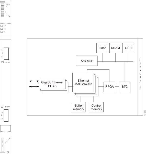
Figure 5-4 shows the card faceplate and a block diagram of the card.
Figure 5-4 E1000-2-G Faceplate and Block Diagram
The E1000-2-G Gigabit Ethernet card provides high-throughput, low-latency packet switching of Ethernet traffic across a SONET network while providing a greater degree of reliability through SONET "self-healing" protection services. This enables network operators to provide multiple 1000-Mbps access drops for high-capacity customer LAN interconnects. It enables efficient transport and co-existence of traditional TDM traffic with packet-switched data traffic.
Each E1000-2-G card supports standards-based, Layer 2 Ethernet switching between its Ethernet interfaces and SONET interfaces on the ONS 15454. The IEEE 802.1Q VLAN tag logically isolates traffic (typically subscribers).
Multiple Ethernet cards installed in an ONS 15454 can act together as a single switching entity or as an independent single switch supporting a variety of SONET port configurations.
You can create logical SONET ports by provisioning STS channels to the packet switch entity within the ONS 15454. Logical ports can be created with a bandwidth granularity of STS-1. The ONS 15454 supports STS-1, STS-3c, STS-6c, or STS-12c circuit sizes.
Note
5.5.1 Compatibility
The E1000-2-G is compatible with XC10G, XC or XCVT cross-connect cards. You can install the card in any multi-speed or high-speed card slots, (Slots 1 to 6 and 12 to 17).
5.5.2 E1000-2-G Card-Level Indicators
The E1000-2-G card faceplate has two card-level LED indicators. (See Table 5-10.)
5.5.3 E1000-2-G Port-Level Indicators
The E1000-2-G card also has one bicolor LED per port. (See Table 5-11.) When the green LINK LED is illuminated, carrier is detected, meaning an active network cable is installed. When the green LINK LED is off, an active network cable is not plugged into the port, or the card is carrying unidirectional traffic. The amber port ACT LED flashes at a rate proportional to the level of traffic being received and transmitted over the port.
5.5.4 E1000-2-G Card Specifications
The E1000-2-G card has the following specifications:
•
–
C-Temp (15454-E1000-2-G): 0 to +55 degrees Celsius
–
–
•
–
–
–
–
•
–
–
5.6 G1000-4 Card
The G1000-4 card requires the XC10G card. The ONS 15454 uses G1000-4 cards for Gigabit Ethernet (1000 Mbps). The G1000-4 card provides four ports of IEEE-compliant, 1000-Mbps interfaces. Each port supports full-duplex operation for a maximum bandwidth of OC-48 on each card.
The G1000-4 card uses GBIC modular receptacles for the optical interfaces. For details, see the "Ethernet Gigabit Interface Converters (GBICs)" section.
Figure 5-5 shows the card faceplate and the block diagram of the card.
Figure 5-5 G1000-4 Faceplate and Block Diagram
The G1000-4 Gigabit Ethernet card provides high-throughput, low latency transport of Ethernet encapsulated traffic (IP and other Layer 2 or Layer 3 protocols) across a SONET network. Carrier-class Ethernet transport is achieved by hitless (< 50 msec) performance in the event of any failures or protection switches (such as 1+1 APS, path protection configuration, or BLSR). Full provisioning support is possible via CTC, TL1, or CTM.
The circuit sizes supported are STS-1, STS-3c, STS-6c, STS-9c, STS-24c and STS-48c.
5.6.1 G1000-4 Card-Level Indicators
The G1000-4 card faceplate has two card-level LED indicators. (See Table 5-12.)
5.6.2 G1000-4 Port-Level Indicators
The G1000-4 card also has one bicolor LED per port. Table 5-13 describes the status that each color represents.
5.6.3 Compatibility
The G1000-4 card requires Cisco ONS 15454 Release 3.2 or later system software and the XC10G cross-connect card. You can install the card into any multi-speed or high-speed traffic slots (Slots 1 to 6 and 12 to 17), for a total shelf capacity of 48 Gigabit Ethernet ports. The practical G1000-4 port per shelf limit is 40, because at least two slots are typically filled by OC-N trunk cards such as the OC-192.
5.6.4 G1000-4 Card Specifications
The G1000-4 card has the following specifications:
•
–
C-Temp (15454-G1000-4): 0 to +55 degrees Celsius–
–
•
–
–
–
–
5.7 G1K-4 Card
The G1K-4 card is the functional equivalent of the G1000-4 card and provides four ports of IEEE-compliant, 1000-Mbps interfaces. Each interface supports full-duplex operation for a maximum bandwidth of 1 Gbps or 2 Gbps bidirectional per port, and 2.5 Gbps or 5 Gbps bidirectional per card. Each port autonegotiates for full duplex and 802.3x flow control. The G1K-4 card uses GBIC modular receptacles for the optical interfaces. For details, see the "Ethernet Gigabit Interface Converters (GBICs)" section.
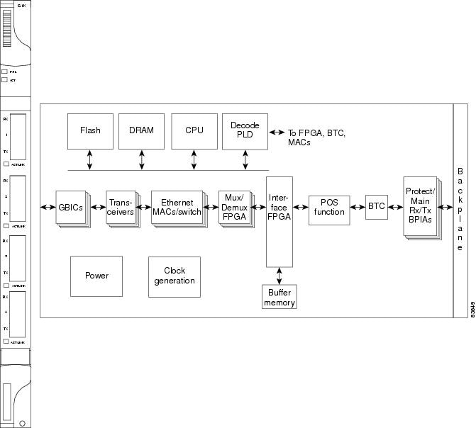
Figure 5-6 shows the card faceplate and the block diagram of the card.
Warning
Figure 5-6 G1K-4 Faceplate and Block Diagram
Warning
The G1K-4 Gigabit Ethernet card provides high-throughput, low-latency transport of Ethernet encapsulated traffic (IP and other Layer 2 or Layer 3 protocols) across a SONET network while providing a greater degree of reliability through SONET "self-healing" protection services. Carrier-class Ethernet transport is achieved by hitless (< 50 ms) performance in the event of any failures or protection switches (such as 1+1 APS, path protection configuration, BLSR, or optical equipment protection) and full provisioning and manageability, as in SONET service. Full provisioning support is possible via CTC or CTM. Each G1K-4 card performs independently of the other cards in the same shelf.
5.7.1 Compatibility
When installed in ONS 15454s running software prior to Software Release 4.0, the G1K-4 cards require the XC10G card to operate. Software R4.0 and later identifies G1K-4 cards as G1K-4s upon physical installation. Software prior to R4.0 identifies both G1000-4 and G1K-4 cards as G1000-4s upon physical installation.
You can install the G1K-4 card into any multi-speed or high-speed traffic slots (Slots 1 to 6 and 12 to 17), for a total shelf capacity of 48 Gigabit Ethernet ports. (The practical limit is 40 ports because at least two slots are typically populated by optical cards such as OC-192).
However, when installed on an ONS 15454 running Software R4.0 and later, the G1K-4 card is not limited to installation in ONS 15454s with XC10G cards but can also be installed in ONS 15454s with XC and XCVT cards. When used with XC and XCVT cards on an ONS 15454 running Release 4.0 and later, the G1K-4 is limited to the high-speed slots (Slots 5, 6, 12, and 13.)
5.7.2 G1K-4 Card-Level Indicators
The G1K-4 card faceplate has two card-level LED indicators, listed in Table 5-14.
5.7.3 G1K-4 Port-Level Indicators
The G1K-4 card has four bicolor LEDs (one LED per port). Table 5-15 describes these LEDs.
5.7.4 G1K-4 Card Specifications
The G1K-4 card has the following specifications:
•
–
–
–
•
–
–
–
–
–
•
ONS 15454 optical cards, when installed in a system, comply with these standards:
–
–
5.8 ML100T-12 Card
The ML100T-12 card provides 12 ports of IEEE 802.3-compliant, 10/100 interfaces. Each interface supports full-duplex operation for a maximum bandwidth of 200 Mbps per port and 2.488 Gbps per card. Each port independently detects the speed of an attached device (autosenses) and automatically connects at the appropriate speed. The ports autoconfigure to operate at either half or full duplex and can determine whether to enable or disable flow control.For ML-Series configuration information, see the Cisco ONS 15454 SONET/SDH ML-Series Multilayer Ethernet Card Software Feature and Configuration Guide.
Figure 5-7 shows the card faceplate.
Caution
Figure 5-7 ML100T-12 Faceplate
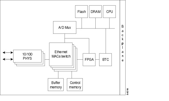
Figure 5-8 shows a block diagram of the ML100T-12 card.
Figure 5-8 ML100T-12 Block Diagram
The ML100T-12 Ethernet card provides high-throughput, low-latency packet switching of Ethernet traffic across an SONET network while providing a greater degree of reliability through SONET "self-healing" protection services. This Ethernet capability enables network operators to provide multiple 10/100-Mbps access drops for high-capacity customer LAN interconnects, Internet traffic, and cable modem traffic aggregation. Efficient transport and co-existence of traditional TDM traffic with packet-switched data traffic are provided.
5.8.1 ML100T-12 Card-Level Indicators
The ML100T-12 card faceplate has three card-level LED indicators, listed in Table 5-16.
5.8.2 ML100T-12 Port-Level Indicators
The ML100T-12 card has 12 pairs of LEDs (one pair for each port) to indicate port conditions. A green L LED indicates that a link is detected. A yellow A LED indicates an active connection. If the A LED is off, it indicates an inactive connection or unidirectional traffic. The port-level indicators are described in Table 5-17.
You can find the status of the ML100T-12 card port using the LCD on the ONS 15454 fan-tray assembly. Use the LCD to view the status of any port or card slot; the LCD displays the number and severity of alarms for a given port or slot. Refer to the Cisco ONS 15454 Troubleshooting Guide for a complete description of the alarm messages.
5.8.3 Compatibility
The ML100T-12 card works in any multi-speed or high-speed card slot, (Slot 1 to 6 or 12 to 17) with the XC10G cross-connect card. It works only in high-speed slots (Slots 5, 6, 12, or 13) with the XC or XCVT cross-connect card.
5.8.4 ML100T-12 Card Specifications
The ML100T-12 card has the following specifications:
•
–
–
–
•
–
–
–
–
–
•
ONS 15454 cards, when installed in a system, comply with these standards:
–
5.9 ML1000-2 Card
The ML1000-2 card provides two ports of IEEE-compliant, 1000-Mbps interfaces. Each interface supports full-duplex operation for a maximum bandwidth of 2 Gbps per port and 4 Gbps per card. Each port autoconfigures for full duplex and IEEE 802.3x flow control.
SFP modules are offered as separate orderable products for maximum customer flexibility. For details, see the "Small Form-Factor Pluggable Connectors (SFPs)" section.
Figure 5-9 shows the ML1000-2 card faceplate.
Warning
Figure 5-9 ML1000-2 Faceplate
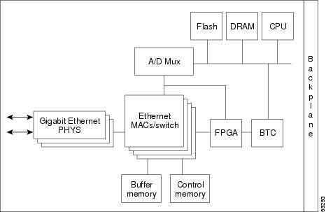
Figure 5-10 shows a block diagram of the ML1000-2 card.
Figure 5-10 ML1000-2 Block Diagram
Warning
The ML1000-2 Gigabit Ethernet card provides high-throughput, low-latency packet switching of Ethernet encapsulated traffic (IP and other Layer 3 protocols) across an SONET network while providing a greater degree of reliability through SONET "self-healing" protection services. This enables network operators to provide multiple 1000-Mbps access drops for high-capacity customer LAN interconnects, Internet traffic, and cable modem traffic aggregation. Efficient transport and co-existence of traditional TDM traffic with packet-switched data traffic is provided.
5.9.1 ML1000-2 Card-Level Indicators
The ML1000-2 card faceplate has three card-level LED indicators, listed in Table 5-18.
5.9.2 ML1000-2 Port-Level Indicators
The ML1000-2 card also has one bicolor LED per port. When the green LINK LED is illuminated, the linkbeat is detected, meaning an active network cable is installed. When the green LINK LED is off, an active network cable is not plugged into the port. The amber port ACT LED flashes at a rate proportional to the level of traffic being received and transmitted over the port.
5.9.3 Compatibility
The ML1000-2 card works in any multi-speed or high-speed card slot, (Slot 1 to 6 or 12 to 17) with the XC10G cross-connect card. It works only in high-speed slots (Slots 5, 6, 12, or 13) with the XC or XCVT cross-connect card.
5.9.4 ML1000-2 Card Specifications
The ML1000-2 card has the following specifications:
•
–
–
–
•
–
–
–
–
–
•
ONS 15454 optical cards, when installed in a system, comply with these standards:
–
–
5.10 GBICs and SFPs
The ONS 15454 Ethernet cards use industry standard small form-factor pluggable connectors (SFPs) and gigabit interface converter (GBIC) modular receptacles. The Gigabit ML-Series card uses SFPs. The Gigabit E-Series card and the G-Series card use Ethernet GBICs. For all Ethernet cards, the type of GBIC or SFP plugged into the card is displayed on the CTC and TL1. Table 5-19 lists the usable GBICs for the E-Series and G-Series ONS 15454 Gigabit Ethernet cards.
5.10.1 Small Form-Factor Pluggable Connectors (SFPs)
The ML-Series Gigabit Ethernet cards use standard Cisco SFPs. SFPs are hot-swappable input/output devices that plug into a Gigabit Ethernet port to link the port to the network. Cisco offers the SFP modules as separate orderable products:
•
The 850-nm SX optics are designed for multimode fiber and distances of up to 722 feet (220 meters) on 62.5 micron fiber and up to 1804 feet (550 meters) on 50 micron fiber.•
The 1300-nm LX optics are designed for single-mode fiber and distances of up to 6.2 miles (10 kilometers).
Note
Table 5-20 lists the usable SFPs for the ML-Series ONS 15454 Gigabit Ethernet cards.
Table 5-20 Usable SFPs for ML-Series Gigabit Ethernet Cards
ML1000-2
IEEE 1000BaseSX compliant 850-nm SFP
IEEE 1000BaseLX compliant 1300-nm SFP (future release)
5.10.2 Ethernet Gigabit Interface Converters (GBICs)
The E-Series and G-Series Gigabit Ethernet cards use standard Cisco GBIC modular receptacles. GBICs are hot-swappable input/output devices that plug into a Gigabit Ethernet port to link the port to the fiber-optic network or network cabling. Cisco offers four GBIC modules as separate orderable products for maximum flexibility:
•
The 850 nm SX optics are designed for multimode fiber and distances of up to 722 feet (220 meters) on 62.5 micron fiber and up to 1804 feet (550 meters) on 50 micron fiber.•
The 1300-nm LX optics are designed for single-mode fiber and distances of up to 6.2 miles (10 kilometers).
Note
•
The 1550-nm ZX optics are designed for single-mode fiber and distances of up to 50 miles (80 kilometers).