Downloads |
 Feedback Feedback
|
Table Of Contents
13.1.1 G1K-4 and G1000-4 Comparison
13.1.3 802.3z Flow Control and Frame Buffering
13.1.4 Ethernet Link Integrity Support
13.1.5 Gigabit EtherChannel/802.3ad Link Aggregation
13.2.2 E-Series IEEE 802.3z Flow Control
13.2.4 E-Series Q-Tagging (IEEE 802.1Q)
13.2.5 E-Series Priority Queuing (IEEE 802.1Q)
13.2.6 E-Series Spanning Tree (IEEE 802.1D)
13.3 G-Series Circuit Configurations
13.3.1 G-Series Point-to-Point Ethernet Circuits
13.3.2 G-Series Manual Cross-Connects
13.4 E-Series Circuit Configurations
13.4.1 E-Series Circuit Protection
13.4.2 Port-mapped Mode and Single-card Etherswitch Circuit Scenarios
13.4.3 ONS 15454 E-Series and ONS 15327 EtherSwitch Circuit Combinations
13.4.4 E-Series Point-to-Point Ethernet Circuits
13.4.5 E-Series Shared Packet Ring Ethernet Circuits
13.4.6 E-Series Hub and Spoke Ethernet Circuit Provisioning
13.4.7 E-Series Ethernet Manual Cross-Connects
13.5 Remote Monitoring Specification Alarm Thresholds
Ethernet Operation
The Cisco ONS 15454 integrates Ethernet into a SONET time-division multiplexing (TDM) platform. The ONS 15454 supports E-Series, G-Series, and ML-Series Ethernet cards. This chapter covers the operation of the E-Series and G-Series Ethernet cards. For Ethernet card specifications, see "Ethernet Cards." For information on the ML-Series cards, refer to the Cisco ONS 15454 ML-Series Multilayer Ethernet Card Software Feature and Configuration Guide. For step-by-step Ethernet card circuit configuration procedures, refer to the "Create Circuits and VT Tunnels" chapter of the Cisco ONS 15454 Procedure Guide.
Chapter topics include:
•
G-Series Circuit Configurations
•
•
13.1 G-Series Application
The G-Series cards (G1000-4/G1K-4) reliably transport Ethernet and IP data across a SONET backbone. The G-Series card maps up to four Gigabit Ethernet interfaces onto a SONET transport network and provides scalable and provisionable transport bandwidth at signal levels up to STS-48c per card. The G-Series card provides line rate forwarding for all Ethernet frames (unicast, multicast, and broadcast) and can be configured to support Jumbo frames (defined as a maximum of 10,000 bytes).The G-series card incorporates features optimized for carrier-class applications such as:
•
•
•
•
The G-Series card allows an Ethernet private line service to be provisioned and managed very much like a traditional SONET or SDH line. G-Series card applications include providing carrier-grade transparent LAN services (TLS), 100 Mbps Ethernet private line services (when combined with an external 100 Mb Ethernet switch with Gigabit uplinks), and high-availability transport for applications such as storage over MAN/WANs.
The card maps a single Ethernet port to a single STS circuit. You can independently map the four ports on the G-Series card to any combination of STS-1, STS-3c, STS-6c, STS-9c, STS-12c, STS-24c, and STS-48c circuit sizes, provided the sum of the circuit sizes that terminate on a card do not exceed STS-48c.
To support a Gigabit Ethernet port at full line rate, an STS circuit with a capacity greater or equal to 1 Gbps (bidirectional 2 Gbps) is needed. An STS-24c is the minimum circuit size that can support a Gigabit Ethernet port at full line rate. The G-Series card supports a maximum of two ports at full line rate.
The G-Series transmits and monitors the SONET J1 Path Trace byte in the same manner as ONS 15454 OC-N cards. For more information on the J1 Path Trace, refer to the "Path Trace" section.
Note
13.1.1 G1K-4 and G1000-4 Comparison
The G1K-4 and the G1000-4 cards comprise the ONS 15454 G-Series and are hardware equivalents.
When installed in ONS 15454s running software prior to Software Release 4.0, both cards require the XC10G card to operate. However, when installed on an ONS 15454 running Software R4.0 and later, the G1K-4 card is not limited to installation in ONS 15454s with XC10G cards but can also be installed in ONS 15454s with XC and XCVT cards. When used with XC and XCVT cards on an ONS 15454 running Release 4.0 and later, the G1K-4 is limited to the high-speed slots (Slots 5, 6, 12, and 13.)
Software R4.0 and later identifies G1K-4 cards as G1K-4s upon physical installation. Software prior to R4.0 identifies both G1000-4 and G1K-4 cards as G1000-4s upon physical installation.
13.1.2 G-Series Example
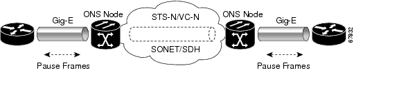
Figure 13-1 shows an example of a G-Series application. In this example, data traffic from the Gigabit Ethernet port of a high-end router travels across the ONS 15454 point-to-point circuit to the Gigabit Ethernet port of another high-end router.
Figure 13-1 Data Traffic On G-Series Point-To-Point Circuit
The G-Series card carries any layer three protocol that can be encapsulated and transported over Gigabit Ethernet, such as IP or IPX. The data is transmitted on the Gigabit Ethernet fiber into the standard Cisco Gigabit Interface Converter (GBIC) on a G-Series card. The G-Series card transparently maps Ethernet frames into the SONET payload by multiplexing the payload onto a SONET OC-N card. When the SONET payload reaches the destination node, the process is reversed and the data is transmitted from the standard Cisco GBIC in the destination G-Series card onto the Gigabit Ethernet fiber.
The G-Series card discards certain types of erroneous Ethernet frames rather than transport them over SONET. Erroneous Ethernet frames include corrupted frames with CRC errors and under-sized frames that do not conform to the minimum 64-byte length Ethernet standard. The G-Series card forwards valid frames unmodified over the SONET network. Information in the headers is not affected by the encapsulation and transport. For example, packets with formats that include IEEE 802.1Q information will travel through the process unaffected.
13.1.3 802.3z Flow Control and Frame Buffering
The G-Series supports IEEE 802.3z flow control and frame buffering to reduce data traffic congestion. To prevent over-subscription, 512 KB of buffer memory is available for the receive and transmit channels on each port. When the buffer memory on the Ethernet port nears capacity, the ONS 15454 uses IEEE 802.3z flow control to transmit a pause frame to the source at the opposite end of the Gigabit Ethernet connection.
The pause frame instructs the source to stop sending packets for a specific period of time. The sending station waits the requested time before sending more data. Figure 13-1 illustrates pause frames being sent and received by ONS 15454s and attached switches.
With Software R4.0 and later, the G-Series card has symmetric flow control and proposes symmetric flow control when auto-negotiating flow control with attached Ethernet devices. Symmetric flow control allows the G-Series to respond to pause frames sent from external devices and send pause frames to external devices. Prior to Software R4.0, flow control on the G-Series card was asymmetric, meaning the card sent pause frames and discarded received pause frames.
This flow-control mechanism matches the sending and receiving device throughput to that of the bandwidth of the STS circuit. For example, a router might transmit to the Gigabit Ethernet port on the G-Series. This particular data rate may occasionally exceed 622 Mbps, but the ONS 15454 circuit assigned to the G-Series port might be only STS-12c (622.08 Mbps). In this example, the ONS 15454 sends out a pause frame and requests that the router delay its transmission for a certain period of time. With flow control and a substantial per-port buffering capability, a private line service provisioned at less than full line rate capacity (STS-24c) is efficient because frame loss can be controlled to a large extent.
Note
Note
13.1.4 Ethernet Link Integrity Support
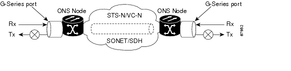
The G-Series supports end-to-end Ethernet link integrity. This capability is integral to providing an Ethernet private line service and correct operation of Layer 2 and Layer 3 protocols on the attached Ethernet devices. End-to-end Ethernet link integrity essentially means that if any part of the end-to-end path fails the entire path fails. Failure of the entire path is ensured by turning off the transmit lasers at each end of the path. The attached Ethernet devices recognize the disabled transmit laser as a loss of carrier and consequently an inactive link.
Figure 13-2 End-to-end Ethernet Link Integrity Support
Note
Note
As shown in Figure 13-2, a failure at any point of the path causes the G-Series card at each end to disable its Tx transmit laser, which causes the devices at both ends to detect a link down. If one of the Ethernet ports is administratively disabled or set in loopback mode, the port is considered a "failure" for the purposes of end-to-end link integrity because the end-to-end Ethernet path is unavailable. The port "failure" also disables both ends of the path.
13.1.5 Gigabit EtherChannel/802.3ad Link Aggregation
The end-to-end Ethernet link integrity feature can be used in combination with Gigabit EtherChannel capability on attached devices. The combination provides an Ethernet traffic restoration scheme that has a faster response time than alternate techniques such as spanning tree rerouting, yet is more bandwidth efficient because spare bandwidth does not need to be reserved.
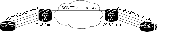
The G-Series supports all forms of link aggregation technologies including Gigabit EtherChannel (GEC), which is a Cisco proprietary standard, and the IEEE 802.3ad standard. The end-to-end link integrity feature of the G-Series allows a circuit to emulate an Ethernet link. This allows all flavors of Layer 2 and Layer 3 rerouting to work correctly with the G-Series. Figure 13-3 illustrates G-Series GEC support.
Figure 13-3 G-Series Gigabit EtherChannel (GEC) Support
Although the G-Series card does not actively run GEC, it supports the end-to-end GEC functionality of attached Ethernet devices. If two Ethernet devices running GEC connect through G-Series cards to an ONS 15454 network, the ONS 15454 SONET side network is transparent to the EtherChannel devices. The EtherChannel devices operate as if they are directly connected to each other. Any combination of G-Series parallel circuit sizes can be used to support GEC throughput.
GEC provides line-level active redundancy and protection (1:1) for attached Ethernet equipment. It can also bundle parallel G-Series data links together to provide more aggregated bandwidth. STP operates as if the bundled links are one link and permits GEC to utilize these multiple parallel paths. Without GEC, STP permits only a single non-blocked path. GEC can also provide G-Series card-level protection or redundancy because it can support a group of ports on different cards (or different nodes) so that if one port or card has a failure, traffic is rerouted over the other port or card.
13.2 E-Series Application
The E-Series cards incorporate Layer 2 switching, whereas the G-Series card is a straight mapper card. The ONS 15454 E-Series cards include the E100T-12/E100T-G and E1000-2/E1000-2-G. An ONS 15454 supports a maximum of ten E-Series cards, and you can insert Ethernet cards in any multipurpose slot.
The E100T-G is the functional equivalent of the E100T-12. The E1000-2 is the functional equivalent of the E1000-2-G. An ONS 15454 using XC10G cards requires the G versions of the E-Series Ethernet cards.
13.2.1 E-Series Modes
An E-Series card operates in one of three modes: multicard EtherSwitch Group, single-card EtherSwitch, or Port-mapped. E-Series cards in multicard EtherSwitch Group or single-card EtherSwitch mode support Layer 2 features, including virtual local area networks (VLANs), IEEE 802.1Q, STP, and IEEE 802.1D. Port-mapped mode configures the E-Series to operate as a straight mapper card and does not support these Layer 2 features. Within an ONS 15454 containing multiple E-Series cards, each E-Series card can operate in any of the three separate modes. At the Ethernet card view in CTC, click the Provisioning > Ether Card tabs to reveal the card modes.
Note
13.2.1.1 E-Series Multicard EtherSwitch Group
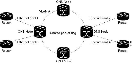
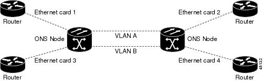
Multicard EtherSwitch Group provisions two or more Ethernet cards to act as a single Layer 2 switch. It supports one STS-6c circuits, two STS-3c circuits, or six STS-1 circuits. Each multicard switch may connect up to a total of STS-6c in SONET circuits. When provisioned as an add or drop node of a shared packet ring circuit, the effective bandwidth doubles, supporting STS-6c in each direction of the ring. Figure 13-4 illustrates a multicard Etherswitch configuration.
Figure 13-4 Multicard EtherSwitch Configuration
Caution
13.2.1.2 E-Series Single-Card EtherSwitch
Single-card EtherSwitch allows each Ethernet card to remain a single switching entity within the ONS 15454 shelf. This option allows STS-12c worth of bandwidth between two Ethernet circuit endpoints. Figure 13-5 illustrates a single-card Etherswitch configuration.
Figure 13-5 Single-card EtherSwitch Configuration
13.2.1.3 Port-Mapped (Linear Mapper)
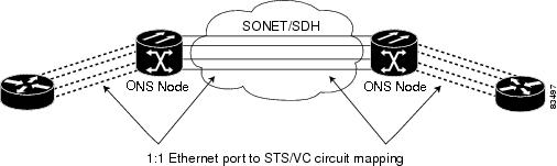
Port-mapped mode, also referred to as linear mapper, configures the E-Series card to map a specific E-Series Ethernet port to one of the card's specific STS circuits. (See Figure 13-6.) Port-mapped mode ensures Layer one transport has low latency for Unicast, multicast, and mixed traffic. Ethernet and Fast Ethernet on the E100T-G card operate at line-rate speed. Gigabit Ethernet transport is limited to a maximum of 600 Mbps because the E1000-2-G has a maximum bandwidth of STS-12c. Ethernet frame sizes up to 1522 bytes are also supported, which allows transport of IEEE 802.1Q tagged frames. The larger maximum frame size of Q-in-Q frames, IEEE 802.1Q in IEEE 802.1Q wrapped frames, are not supported.
Figure 13-6 E-Series Mapping Ethernet Ports To SONET STS circuits
Port-mapped mode disables Layer 2 functions supported by the E-Series in single-card and multicard mode, including STP, VLANs, and MAC address learning. It significantly reduces the service-affecting time for cross-connect and TCC+/TCC2 card switches.
Port-mapped mode does not support VLANs in the same manner as multicard and single-card mode. The ports of E-Series cards in multicard and single-card mode can join specific VLANs. E-Series cards in port-mapped mode do not have this Layer 2 capability and only transparently transport external VLANs over the mapped connection between ports. An E-Series card in port-mapped mode does not inspect the tag of the transported VLAN, so a VLAN range of 1 through 4096 can be transported in port-mapped mode.
Port-mapped mode does not perform any inspection or validation of the Ethernet frame header. The Ethernet Cyclic Redundancy Check (CRC) is validated, and any frame with an invalid Ethernet CRC is discarded.
Port-mapped mode also allows the creation of STS circuits between any two E-Series cards, including the E100T-G, E1000-G, or the E10/100-4 (the ONS 15327 E-Series card). Port-mapped mode does not allow an E-Series cards to connect to the ML-Series or G-Series cards.
13.2.2 E-Series IEEE 802.3z Flow Control
The E100T-G in any mode and the E1000-G in port-mapped mode support IEEE 802.3z symmetrical flow control and propose symmetric flow control when auto-negotiating with attached Ethernet devices. For flow control to operate, both the E-Series port and the attached Ethernet device must be set to auto-negotiation (AUTO) mode. The attached Ethernet device may also need to have flow control enabled. The flow-control mechanism allows the E-Series to respond to pause frames sent from external devices and send pause frames to external devices.
Flow control matches the sending and receiving device throughput to that of the bandwidth of the STS circuit. For example, a router might transmit to the Gigabit Ethernet port on the E-Series in port mapped mode. The data rate transmitted by the router may occasionally exceed 622 Mbps, but the ONS 15454 circuit assigned to the E-Series port in port-mapped mode is a maximum of STS-12c (622.08 Mbps). In this scenario, the ONS 15454 sends out a pause frame and requests that the router delay its transmission for a certain period of time.
Note
13.2.3 E-Series VLAN Support
Users can provision up to 509 VLANs per network with the CTC software. Specific sets of ports define the broadcast domain for the ONS 15454. The definition of VLAN ports includes all Ethernet and packet-switched SONET port types. All VLAN IP address discovery, flooding, and forwarding is limited to these ports.
The ONS 15454 IEEE 802.1Q-based VLAN mechanism provides logical isolation of subscriber LAN traffic over a common SONET transport infrastructure. Each subscriber has an Ethernet port at each site, and each subscriber is assigned to a VLAN. Although the subscriber's VLAN data flows over shared circuits, the service appears to the subscriber as a private data transport.
Note
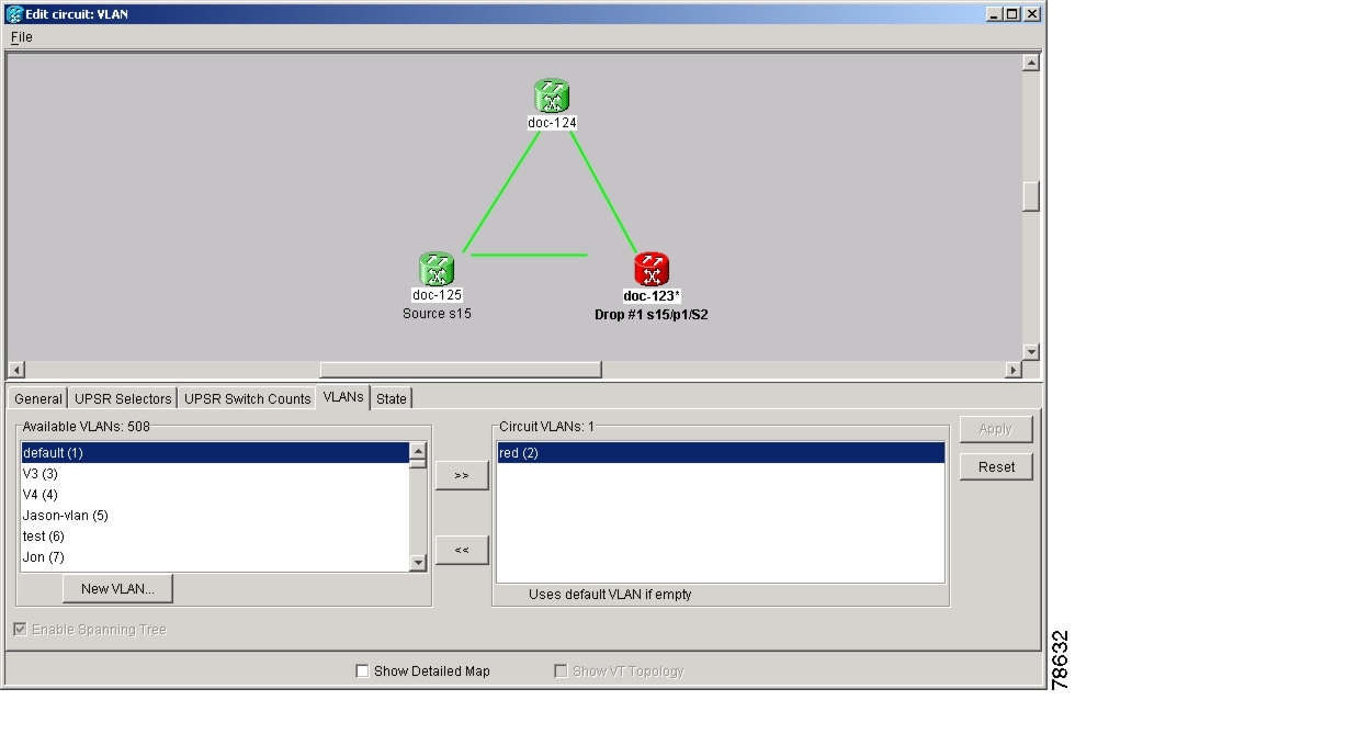
The number of VLANs used by circuits and the total number of VLANs available for use appears in CTC on the VLAN counter. (See Figure 13-7.)
Figure 13-7 Edit Circuit Dialog Featuring Available VLANs
13.2.4 E-Series Q-Tagging (IEEE 802.1Q)
E-Series cards in single-card and multicard mode support IEEE 802.1Q. IEEE 802.1Q allows the same physical port to host multiple 802.1Q VLANs. Each 802.1Q VLAN represents a different logical network. E-Series cards in port-mapped mode transport IEEE 802.1Q tags (Q-tags), but do not remove or add these tags.
The ONS 15454 works with Ethernet devices that support IEEE 802.1Q and those that do not support IEEE 802.1Q. If a device attached to an ONS 15454 Ethernet port does not support IEEE 802.1Q, the ONS 15454 uses Q-tags internally only. The ONS 15454 associates these Q-tags with specific ports.
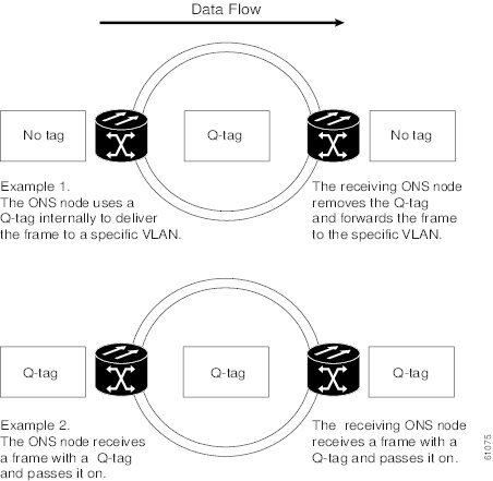
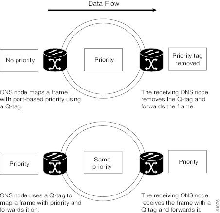
With Ethernet devices that do not support IEEE 802.1Q, the ONS 15454 takes non-tagged Ethernet frames that enter the ONS network and uses a Q-tag to assign the packet to the VLAN associated with the ONS network's ingress port. The receiving ONS node removes the Q-tag when the frame leaves the ONS network (to prevent older Ethernet equipment from incorrectly identifying the 8021.Q packet as an illegal frame). The ingress and egress ports on the ONS network must be set to Untag for the removal to occur. Untag is the default setting for ONS ports. Example 1 in Figure 13-8 illustrates Q-tag use only within an ONS network.
The ONS 15454 uses the Q-tag attached by the external Ethernet devices that support IEEE 802.1Q. Packets enter the ONS network with an existing Q-tag; the ONS 15454 uses this same Q-tag to forward the packet within the ONS network and leaves the Q-tag attached when the packet leaves the ONS network. The entry and egress ports on the ONS network must be set to Tagged for this process to occur. Example 2 in Figure 13-8 illustrates the handling of packets that both enter and exit the ONS network with a Q-tag.
For more information about setting ports to Tagged and Untag, refer to the (DLP102) Provision E-Series Ethernet Ports for VLAN Membership in the Cisco ONS 15454 Procedure Guide.
Caution
Figure 13-8 Q-tag Moving Through VLAN
13.2.5 E-Series Priority Queuing (IEEE 802.1Q)
Networks without priority queuing handle all packets on a first-in-first-out basis. Priority queuing reduces the impact of network congestion by mapping Ethernet traffic to different priority levels. The ONS 15454 supports priority queuing. The ONS 15454 maps the eight priorities specified in IEEE 802.1Q to two queues, low priority and high priority (Table 13-1). Q-tags carry priority queuing information through the network. (See Figure 13-9.)
The ONS 15454 uses a "leaky bucket" algorithm to establish a weighted priority (not a strict priority). A weighted priority gives high-priority packets greater access to bandwidth, but does not totally preempt low-priority packets. During periods of network congestion, roughly 70 percent of bandwidth goes to the high-priority queue and the remaining 30 percent goes to the low-priority queue. A network that is too congested will drop packets.
Note
Note
Note
Table 13-1 Priority Queuing
0,1,2,3
Low
30%
4,5,6,7
High
70%
Figure 13-9 Priority Queuing Process
13.2.6 E-Series Spanning Tree (IEEE 802.1D)
The Cisco ONS 15454 operates spanning tree protocol (STP) according to IEEE 802.1D, when an Ethernet card is installed. The E-Series Card supports common STPs on a per circuit basis up to a total of eight STP instances. It does not support per-VLAN STP. In single-card mode, STP can be disabled or enabled on a per circuit basis during circuit creation. Disabling STP will preserve the number of available STP instances.
STP operates over all packet-switched ports including Ethernet and OC-N ports. On Ethernet ports, STP is enabled by default but may be disabled. A user can also disable or enable STP on a circuit-by-circuit basis on unstitched Ethernet cards in a point-to-point configuration. However, turning off STP protection on a circuit-by-circuit basis means that the ONS 15454 system is not protecting the Ethernet traffic on this circuit, and the Ethernet traffic must be protected by another mechanism in the Ethernet network. On OC-N interface ports, the ONS 15454 activates STP by default, and STP cannot be disabled.
The Ethernet card can enable STP on the Ethernet ports to create redundant paths to the attached Ethernet equipment. STP connects cards so that both equipment and facilities are protected against failure.
STP detects and eliminates network loops. When STP detects multiple paths between any two network hosts, STP blocks ports until only one path exists between any two network hosts (Figure 13-10). The single path eliminates possible bridge loops. This is crucial for shared packet rings, which naturally include a loop.
Figure 13-10 STP Blocked Path
To remove loops, STP defines a tree that spans all the switches in an extended network. STP forces certain redundant data paths into a standby (blocked) state. If one network segment in the STP becomes unreachable, the STP algorithm reconfigures the STP topology and reactivates the blocked path to reestablish the link. STP operation is transparent to end stations, which do not discriminate between connections to a single LAN segment or to a switched LAN with multiple segments. The ONS 15454 supports one STP instance per circuit and a maximum of eight STP instances per ONS 15454.
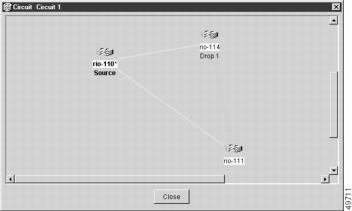
The Circuit window shows forwarding spans and blocked spans on the spanning tree map. (See Figure 13-11.)
Figure 13-11 Spanning Tree Map On Circuit Window
Note
Caution
Note
13.2.6.1 E-Series Multi-Instance Spanning Tree and VLANs
The ONS 15454 can operate multiple instances of STP to support VLANs in a looped topology. You can dedicate separate circuits across the SONET ring for different VLAN groups. Each circuit runs its own STP to maintain VLAN connectivity in a multiring environment.
13.2.6.2 Spanning Tree on a Circuit-by-Circuit Basis
You can also disable or enable STP on a circuit-by-circuit basis on single-card EtherSwitch E-Series cards in a point-to-point configuration. This feature allows customers to mix spanning tree protected circuits with unprotected circuits on the same card. It also allows two single-card EtherSwitch E-Series cards on the same node to form an intranode circuit.
13.2.6.3 E-Series Spanning Tree Parameters
Default STP parameters are appropriate for most situations. (See Table 13-2.) Contact the Cisco Technical Assistance Center (TAC) at 1-877-323-7368 before you change the default STP parameters.
13.2.6.4 E-Series Spanning Tree Configuration
To view the spanning tree configuration, at the node view click the Provisioning > Etherbridge > Spanning Trees tabs. (See Table 13-3.)
13.3 G-Series Circuit Configurations
This section explains G-Series point-to-point circuits and manual cross-connects. Ethernet manual cross-connects allow you to cross connect individual Ethernet circuits to an STS channel on the ONS 15454 optical interface and also to bridge non-ONS SONET network segments.
13.3.1 G-Series Point-to-Point Ethernet Circuits
G-Series cards support point-to-point circuit configurations. (See Figure 13-12.) Provisionable circuit sizes are STS 1, STS 3c, STS 6c, STS 9c, STS 12c, STS 24c, and STS 48c. Each Ethernet port maps to a unique STS circuit of the G-Series card.
Figure 13-12 G-Series Point-to-point circuit
The G-Series supports any combination of up to four circuits from the list of valid circuit sizes; however, the circuit sizes can add up to no more than 48 STSs.
Due to hardware constraints, the card imposes an additional restriction on the combinations of circuits that can be dropped onto a G-Series card. These restrictions are transparently enforced by the ONS 15454, and you do not need to keep track of restricted circuit combinations.
When a single STS-24c terminates on a card, the remaining circuits on that card can be another single STS-24c or any combination of circuits of STS-12c size or less that add up to no more than 12 STSs (that is a total of 36 STSs on the card).
If STS-24c circuits are not being dropped on the card, the full 48 STSs bandwidth can be used with no restrictions (for example using either a single STS-48c or 4 STS-12c circuits).
Note
Note
Note
Caution
13.3.2 G-Series Manual Cross-Connects
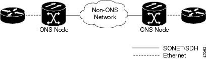
ONS 15454s require end-to-end CTC visibility between nodes for normal provisioning of Ethernet circuits. When other vendors' equipment sits between ONS 15454s, OSI/TARP-based equipment does not allow tunneling of the ONS 15454 TCP/IP-based DCC. To circumvent a lack of continuous DCC, the Ethernet circuit must be manually cross connected to an STS channel using the non-ONS network. Manual cross-connects allows an Ethernet circuit to run from ONS node to ONS node while utilizing the non-ONS network. (See Figure 13-13.)
Note
Figure 13-13 G-Series Manual Cross-connects
13.4 E-Series Circuit Configurations
Ethernet circuits can link ONS nodes through point-to-point (straight), shared packet ring, or hub and spoke configurations. Two nodes usually connect with a point-to-point configuration. More than two nodes usually connect with a shared packet ring configuration or a hub-and-spoke configuration. Ethernet manual cross-connects allow you to cross connect individual Ethernet circuits to an STS channel on the ONS 15454 optical interface and also to bridge non-ONS SONET network segments. For step-by-step procedures to configure E-Series circuits, see the "Create Circuits and VT Tunnels" chapter of the Cisco ONS 15454 Procedure Guide.
13.4.1 E-Series Circuit Protection
Different combinations of E-Series circuit configurations and SONET network topologies offer different levels of E-Series circuit protection. Table 13-4 details the available protection.
Caution
Note
Note
13.4.2 Port-mapped Mode and Single-card Etherswitch Circuit Scenarios
Seven scenarios exist for provisioning circuits on an E-Series card in single-card EtherSwitch or Port-mapped mode:
1.
2.
3.
4.
5.
6.
7.
Note
13.4.3 ONS 15454 E-Series and ONS 15327 EtherSwitch Circuit Combinations
Table 13-5 shows the Ethernet circuit combinations available in ONS 15454 E-Series cards and ONS 15327 E-Series cards.
13.4.4 E-Series Point-to-Point Ethernet Circuits
The ONS 15454 can set up a point-to-point (straight) Ethernet circuit as single-card, port-mapped, or multicard circuit. Multicard EtherSwitch limits bandwidth to STS-6c of bandwidth between two Ethernet circuit points, but allows adding nodes and cards and making a shared packet ring. (See Figure 13-14.) Single-card EtherSwitch and Port-mapped mode allows a full STS-12c of bandwidth between two Ethernet circuit endpoints. (See Figure 13-15.)
Figure 13-14 Multicard EtherSwitch Point-to-point Circuit
Figure 13-15 Single-card EtherSwitch Or Port-mapped Point-to-point Circuit
Note
13.4.5 E-Series Shared Packet Ring Ethernet Circuits
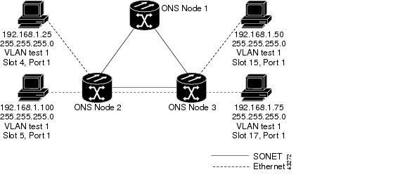
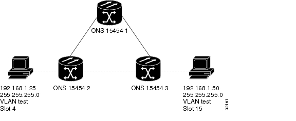
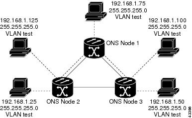
A shared packet ring allows additional nodes, besides the source and destination nodes, access to an Ethernet STS circuit. The E-Series card ports on the additional nodes can share the circuit's VLAN and bandwidth. Figure 13-16 illustrates a shared packet ring. Your network architecture may differ from the example.
Figure 13-16 Shared Packet Ring Ethernet Circuit
13.4.6 E-Series Hub and Spoke Ethernet Circuit Provisioning
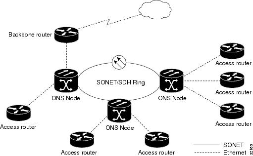
The hub and spoke configuration connects point-to-point circuits (the spokes) to an aggregation point (the hub). In many cases, the hub links to a high-speed connection and the spokes are Ethernet cards. Figure 13-17 illustrates a hub and spoke ring. Your network architecture may differ from the example.
Figure 13-17 Hub And Spoke Ethernet Circuit
13.4.7 E-Series Ethernet Manual Cross-Connects
ONS 15454s require end-to-end CTC visibility between nodes for normal provisioning of Ethernet circuits. When other vendors' equipment sits between ONS 15454s, OSI/TARP-based equipment does not allow tunneling of the ONS 15454 TCP/IP-based DCC. To circumvent this lack of continuous DCC, the Ethernet circuit must be manually cross connected to an STS channel using the non-ONS network. The manual cross-connect allows an Ethernet circuit to run from ONS node to ONS node utilizing the non-ONS network.
Note
13.5 Remote Monitoring Specification Alarm Thresholds
The ONS 15454 features remote monitoring (RMON) that allows network operators to monitor the health of the network with a network management system (NMS).
One of the ONS 15454's RMON MIBs is the Alarm group, which consists of the alarmTable. An NMS uses the alarmTable to find the alarm-causing thresholds for network performance. The thresholds apply to the current 15-minute interval and the current 24-hour interval. RMON monitors several variables, such as Ethernet collisions, and triggers an event when the variable crosses a threshold during that time interval. For example, if a threshold is set at 1000 collisions and 1001 collisions occur during the 15-minute interval, an event triggers. CTC allows you to provision these thresholds for Ethernet statistics.
Note