Feedback Feedback
|
Table Of Contents
Implementing VLANs in Your Ethernet Network
Add End-User Ports to the VLAN
Enable or Disable the VLAN on a Trunk
Where You Should End Up—Verification
Implementing VLANs in Your Ethernet Network
As a network administrator for a company, you are constantly looking for ways to improve your network manageability, performance, and security. You have done some research and have learned about the benefits of VLANs: simplification of moves, adds, and changes; controlled broadcast activity; and workgroup and network security (see VLANs).
In this scenario, let's assume the network configuration consists of ten LAN switches and several VLANs in a VTP domain called "North Carolina." You can use Topology Services to help you manage these VLANs and create additional VLANs easily.
Note
The network design used in this scenario is intended to illustrate how to use Campus Manager applications to manage your network, not as guidelines for how to design your network. Consult the network design guidelines for that type of information.
This scenario focuses on creating a new Ethernet VLAN and moving port into this VLAN. To create a Token Ring VLAN, the steps are essentially the same; however the menu options are different. Refer to the Topology Services online help for the procedure for creating Token Ring VLANs.
To create the Ethernet VLAN as described in this scenario, refer to these sections:
•
What You Need—Prerequisites
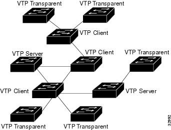
VTP must be implemented in your network and you must have at least one VTP server established. In this particular network scenario, there are two VTP servers, three VTP clients, and five switches in VTP transparent mode. See "VTP Domains" in "Managing Physical and Logical Network Services with Topology Services." You should also check for discrepancies in your network. See Figure 6-1 for an network diagram of the North Carolina VTP domain.
To do this, follow these steps:
Step 1
Step 2
Make sure that the discrepancies that you are interested in are being collected. If you find discrepancies, you should resolve them before proceeding. Once you believe you have resolved the discrepancies, you should rediscover the network and check for discrepancies again. Continue this process until all discrepancies have been resolved.
Figure 6-1 North Carolina VTP Domain Network Configuration
How to Do It—Procedure
Use these procedures to implement VLANs in your network:
2.
3.
Create an Ethernet VLAN
To create an Ethernet VLAN:
Step 1
Step 2
•
•
Step 3
Step 4
Step 5
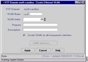
Figure 6-2 Create Ethernet VLAN Window
Add End-User Ports to the VLAN
After you have successfully created the VLAN in the North Carolina VTP domain, you can now add end-user ports (non-trunking ports) from one or more devices to this VLAN. To add ports to the VLAN:
Step 1
Step 2
Step 3
Step 4
Step 5
If you are selecting ports from a switch that is in transparent mode, the VLAN that you are moving the ports to must exist on that switch.
Step 6
Step 7
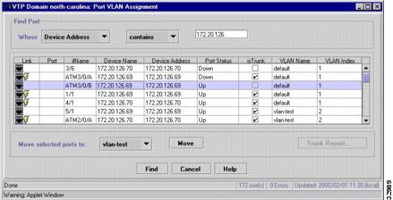
Figure 6-3 Port VLAN Assignment Window
Enable or Disable the VLAN on a Trunk
When you create a VLAN, trunks might be automatically included if the trunk has been configured to allow the index number for the VLAN you just created. For example, if the range of VLAN index numbers is from 1 to 1024, and you create a VLAN with an index number 65, which falls within that range, the trunk is automatically included on VLAN 65. You might need to enable or disable the VLAN on a trunks to fit the configuration you desire. In this scenario, you will enable the VLAN on a trunk. To enable a VLAN on a trunk:
Step 1
Step 2
Step 3
Step 4
Step 5
Step 6
Step 7
Step 8
Where You Should End Up—Verification
To confirm the creation of the VLAN and the VTP configuration:
Step 1
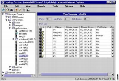
See Figure 6-4 for an example of this information which is shown in the VLAN Summary window.
Step 2
Figure 6-4 VLAN Summary Window