Downloads |
 Feedback Feedback
|
Table Of Contents
Tracking Packet Flow Using Path Analysis
Starting and Navigating in Path Analysis
VLAN/ELAN Subnet Mapping Table and Layer 2 Tracing
VLAN/ELAN Subnet Mapping Table and Layer 3 Tracing
Tracking Packet Flow Using Path Analysis
Path Analysis is an operations and diagnostic application that traces the connectivity between two specified points on your network and the physical and logical paths taken by packets flowing between those points.
Use Path Analysis to:
•
Analyze paths between two specified Layer 2 or Layer 3 devices using device host names or IP addresses, and show results visually in a network map, in a table, or in a textual "trace" display.
•
•
•
•
•
•
•
•
The following topics provide you with information about:
•
Starting and Navigating in Path Analysis
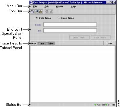
From the CiscoWorks2000 desktop, select Campus Manager > Path Analysis. The Path Analysis main window appears (see Figure 4-1). Refer to Table 4-1 for a description of the elements of the Path Analysis main window.
Figure 4-1 Path Analysis Main Window
Table 4-1
Menu Bar
Contains Path Analysis Commands
None.
Tool Bar
Provides quick access to frequently used menu options
None.
Endpoint Specification Panel
Contains fields for specifying the start and end points for a trace
You can specify a Cisco devices or end-user stations.
Trace Results Tabbed Panel
Displays the results of the trace in Map, Trace, and Table format
Click on the desired tab to display the results in each format.
Status Bar
Displays informational, diagnostic, and warning messages regarding Layer 3 traces
A complete list of status bar messages appears in "Troubleshooting Campus Manager," "What do the status bar and alert box messages mean?"
Path Analysis Main Window Elements
Using Path Analysis
Table 4-2 lists the main tasks that you can perform using Path Analysis. All actions begin from the Path Analysis main window, unless otherwise noted.
Path Analysis Concepts
You should understand these concepts when using Path Analysis:
•
•
Path Analysis Requirements
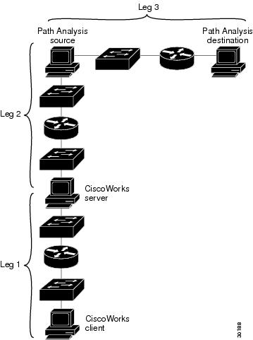
There are four main components in Path Analysis as shown in Figure 4-2:
•
•
•
•
Path Analysis investigates and reports on Layer 3 and Layer 2 paths between a source and destination (Leg 3 in Figure 4-2). For Path Analysis to be able to perform this analysis on Leg 3, Legs 1 and 2 must be functional.
For the path between the client and server (Leg 1) to be functional, there must be problem-free communication between server and client. (For example, problematic communication results when a firewall exists between the client and server.)
For the path between the server and the source (Leg 2) to be functional, the following requirements must be met:
•
•
•
no ip source-route
Note
Figure 4-2 Path Analysis Components
For Layer 2 analysis to take place between the source and destination (Leg 3), the following conditions must be met:
•
•
•
•
•
•
•
•
•
Note
Valid Trace End Points
You can select source and destination end-points for a trace:
•
•
•
A trace source end-point must be inside the managed organization for accurate Path Analysis results, and can be either:
•
•
A trace source end-point must be a Cisco device for Layer 2 tracing. Layer 3 tracing supports any trace source end-point inside the managed organization.
A trace source end-point must be reachable from the CiscoWorks2000 server. If it is not reachable, an alert message appears. See the See the "What do the status bar and alert box messages mean?" section in section in "Troubleshooting Campus Manager."
A trace destination end-point can be any IP address or DNS name on the Internet, including addresses outside the managed organization. But firewalls and devices along the path that do not support source-routed IP packets can prevent Path Analysis from completing a trace to its intended destination. Layer 2 tracing, where possible, occurs only inside the managed organization.
Note
It is possible to specify a source end-point outside of the managed domain, but trace results from this usage might not be completely accurate. Therefore, Cisco Systems recommends against this usage.
Layer 3 Paths
The Layer 3 path is the logical path on the network that packets follow through Cisco devices such as routers. Layer 3, known also as the network layer, represents the logical network, the network at the Internet Protocol (IP) level. Layer 3 path displays the end-points and routers on the network.
Layer 3 output from Path Analysis is similar to the output of the UNIX and Windows NT traceroute command, but is more detailed.
Path Analysis supports only the IP protocol at this time. AppleTalk and IPX are not supported.
Layer 3 tracing does not support PCs or workstations with more than one network adapter.
Layer 2 Paths
The Layer 2 path is the physical path on the network that packets follow through Cisco devices.
The Layer 2 path includes devices that are either Simple Network Management Protocol (SNMP) accessible and known through Topology Services, or are SNMP inaccessible but have been discovered by User Tracking (for example, end-user hosts).
The Layer 2 path provides further resolution of the Layer 3 path, but is not necessarily a complete representation of all Layer 2 devices. For example, hubs or other devices that do not support the Cisco Discovery Protocol (CDP) do appear in the Layer 2 traces.
Path Analysis uses Asynchronous Network Interface (ANI) information to build Layer 2 paths, combining:
•
•
•
•
Path Analysis supports Layer 2 tracing on Ethernet, Fast Ethernet, Gigabit Ethernet, and LAN Emulation networks. LAN Emulation support includes tracing on the path inside an ATM cloud. For this release, Path Analysis Layer 2 tracing does not support FDDI, Token Ring, and WAN interfaces or router bridge groups.
Note
Shortcuts
Shortcut connections occur in the Layer 2 path where packets are IP-switched after the router has determined the next-hop destination.
Shortcuts appear in the Layer 2 path as connections between switch ports, which bypass intervening routers. Currently, the only shortcuts reported are those provided by the Cisco Catalyst 5000 switches.
You can recognize shortcuts in the Map display in one of two ways:
•
•
Subnet to VLAN/ELAN Mapping
The VLAN/ELAN Subnet Mapping Table displays VLAN, ELAN, and associated subnet mappings. This information can be useful when performing Layer 3 traces and is required in order to perform Layer 2 traces.
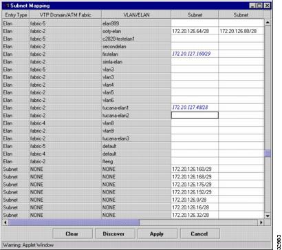
You should view the VLAN/ELAN Subnet Mapping Table during the initial setup of Path Analysis and whenever your subnet mapping changes. To view the table, select Action > Subnet Mapping. The VLAN/ELAN Subnet Mapping Table window appears, similar to the one shown in Figure 4-3. If you need to, you can add or delete entries in the table, or discover a fresh set of information.
Figure 4-3 VLAN/ELAN Subnet Mapping Table
On a typical network, information displayed in the table is discovered automatically by the Path Analysis application. It is therefore unlikely that you would need to insert additional entries manually.
The first three columns in the VLAN/ELAN Subnet Mapping Table contain text that cannot be edited. The column headings are Entry Type, VTP Domain/ATM Fabric, and VLAN/ELAN. You can edit the text in any Subnet column.
One of three font styles is used to render information in a cell. The use of a particular font conveys information about the source and validity of a mapping:
•
•
•
Note
To verify whether you must enter information manually, click Clear, and then Discover to see the automatically discovered mapping of subnets to VLANs or ELANs, as well as subnets that do not map to any VLAN or ELAN. If you know the information is incomplete, you must enter the missing information manually.
The results of automatic discovery might vary slightly over time, even if the structure of your network is unchanged. If you obtain a complete set of information using discovery, you might want to apply that information to the server, in case subsequent discoveries are incomplete.
Note
VLAN/ELAN Subnet Mapping Table and Layer 2 Tracing
There are three types of entries in this table: VLAN, ELAN, and Subnet. For each VLAN or ELAN entry in the table, the user can specify the subnets that reside on that VLAN/ELAN. If this information is not provided manually and cannot be discovered automatically, Layer 2 tracing cannot occur on that subnet.Therefore, you should check the automatically discovered values following an installation, and enter any needed information. If information is missing from the VLAN/ELAN mapping table, no Layer 2 traces are performed on those subnets with missing mapping information.
The following conditions are acceptable mappings:
•
•
•
VLAN/ELAN Subnet Mapping Table and Layer 3 Tracing
Layer 3 path tracing uses the Subnet Mapping Table in a limited way.
Successful Layer 3 tracing requires that all subnets within the managed domain are listed in one of the table rows.
Use this information to identify non-Cisco or non-Cisco Discovery Protocol (CDP) devices. These are devices that are not discovered or displayed in Topology Services views.
Layer 3 traces would generally access these devices through SNMP unless they reside on a known, managed subnet within the organization. Layer 3 path traces determine whether these devices are on a known, managed subnet by referencing them to the VLAN/ELAN Mapping Table.
If a subnet has no entry in the table, there will be no SNMP information in the table view or outgoing interface information for the non-Cisco or non-CDP devices on that subnet. Layer 3 path traces will function properly in all other respects, however.
The Entry Type column shows three types of entries: Vlan, Elan, and Subnet.
If the Entry Type column shows Vlan or Elan, subnets for corresponding VLANs or ELANs are listed in the Subnet column(s) for that row.
If the Entry Type column shows Subnet, the stand-alone subnet (one that does not map to a VLAN or ELAN) appears in the first Subnet column for that row. Do not add entries in the Subnet column for stand-alone subnets.