-
Installation Guide for the Cisco 1120 Secure Access Control Server 4.2
-
Preface
-
Cisco 1120 Secure Access Control Server Overview
-
Preparing for Installation
-
Installing and Configuring the Cisco 1120 Secure Access Control Server 4.2
-
Administering the Cisco 1120 Secure Access Control Server
-
Upgrading and Migrating to Cisco 1120 Secure Access Control Server
-
Site Log
-
Windows Service Advisement
-
Command Reference
-
Troubleshooting
-
Maintaining the Cisco 1120 Secure Access Control Server
-
Index
-
 Feedback
Table Of Contents
Cisco 1120 Secure Access Control Server Overview
Specifications for the CSACS 1120 Series Appliance
Product Serial Number Location
Cisco Product Identification Tool
CSACS 1120 Appliance Front-Panel View
CSACS 1120 Appliance Back-Panel View
Input/Output Ports and Connectors
Ethernet Port (NIC 1 and NIC 2)
Overtemperature Protection (OTP)
Cisco 1120 Secure Access Control Server Overview
This chapter gives a functional overview of the Cisco 1120 Secure Access Control Server, hereafter referred to as CSACS 1120. This chapter covers the appliance hardware, major components, controls, connectors, and front- and rear-panel LED indicators.
This chapter contains:
System Description
The Cisco 1120 Secure Access Control Server (CSACS 1120) is a highly scalable, rack-mounted, dedicated platform that serves as a high-performance access control server supporting centralized Remote Access Dial-In User Service (RADIUS) and Terminal Access Controller Access Control System (TACACS+). CSACS 1120 controls the authentication, authorization, and accounting (AAA) of users accessing corporate resources through the network.
You use CSACS 1120 to control who can access the network, to authorize what types of network services are available for particular users or groups of users, and to keep an accounting record of all user actions in the network. The appliance supports access control and accounting for dial-up access servers, firewalls and VPNs, Voice-over-IP solutions, content networking, and switched and wireless local area networks (LANs and WLANs). In addition, you can use the same AAA framework, via TACACS+, to manage administrative roles and groups and to control how network administrators change, access, and configure the network internally.
CSACS 1120 provides almost the same set of features and functions as in the Cisco Secure ACS for Windows Server (the software product) in a dedicated, security hardened, application-specific, appliance packaging. CSACS 1120 includes additional features specific to operating and managing the ACS appliance.
To ensure a highly secure posture, CSACS 1120:
•
Runs only the necessary services of the underlying hardened Windows operating system. (See Appendix C, "Windows Service Advisement," for details on the hardening.)
•
•
•
•
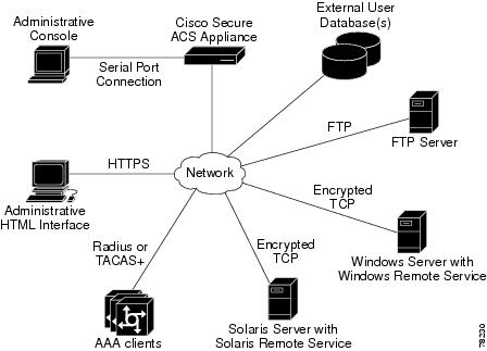
Figure 1-1 shows the CSACS 1120 operating context.
Figure 1-1 CSACS 1120 Context Diagram
The administrative console in the context diagram represents any data terminal equipment (DTE) capable of supporting administrative connection via a serial port connection and is generally referred to as a console in this guide.
Product Overview
This section describes the power requirements, rack-mount hardware kit, and features of the CSACS 1120 Series appliance.
This section contains:
•
•
•
Specifications for the CSACS 1120 Series Appliance
The CSACS 1120 Series appliance (see Figure 1-2) is contained in a standard shelf-rack enclosure. The appliance weighs from 15 lb (9.071 kg) to 33 lb (14.96 kg) depending on what options are installed in the appliance. It measures 1.69 inches high x 17 inches wide x 20 inches deep (4.29 cm x 43.18 cm x 50.80 cm). These dimensions do not include the rack handles.
Figure 1-2 Cisco 1120 Secure Access Control System Front View
The CSACS 1120 Series appliance is configured for AC-input power and has a single auto-ranging AC-input power supply, mounted in a standard 19-inch (48.3 cm), 4-post equipment rack (using the rack-mount brackets provided). The CSACS 1120 features include:
•
•
•
•
•
•
•
•
•
•
•
•
•
•
–
–
–
For a description of the LEDs, see CSACS 1120 Appliance Front-Panel View.
•
Note
Product Serial Number Location
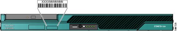
The serial number label is located on the front-panel of the CSACS 1120 Series appliance, at the lower Left. Figure 1-3 shows the location of this label.
Figure 1-3 CSACS 1120 Appliance Serial Number Location
Note
Cisco Product Identification Tool
The Cisco Product Identification (CPI) tool helps you retrieve the serial number of your Cisco products.
Before you submit a request for service online or by phone, use the CPI tool to locate your product serial number. You can access this tool from the Cisco Support website.
To access this tool:
Step 1
Step 2
Step 3
This tool offers three search options:
•
•
•
Search results show an illustration of your product with the serial number label location highlighted. Locate the serial number label on your product and record the information before you place a service call.
You can access the CPI tool at:
http://tools.cisco.com/Support/CPI/index.do
To access the CPI tool, you require a Cisco.com user ID and password. If you have a valid service contract but do not have a user ID or password, you can register at:
http://tools.cisco.com/RPF/register/register.do
Hardware Features
This section describes the front- and rear-panel controls, ports, and LED indicators on the CSACS 1120 Series appliance.
This section contains:
•
•
•
CSACS 1120 Appliance Front-Panel View
The front-panel of the CSACS 1120 Series appliance contains:
•
•
•
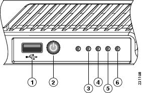
Figure 1-4 shows the components of the front-panel.
Figure 1-4 CSACS 1120 Series Appliance Front View
The following table describes the callouts in Figure 1-4.
USB port
Hard disk drive activity LED
Power button
NIC 1 LED
Appliance power LED
NIC 2 LED
LEDs
Table 1-1 describes the LEDs located on the front-panel of the CSACS 1120 Series appliance.
Note
CSACS 1120 Appliance Back-Panel View
The back panel of the CSACS 1120 Series appliance contains:
•
•
•
•
•
•
•
•
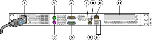
Figure 1-5 shows the components of the back panel.
Note
Figure 1-5 CSACS 1120 Series Appliance Rear View
The following table describes the callouts in Figure 1-5
.
Note
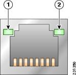
LEDs
The back panel of the CSACS 1120 Series appliance contains LEDs that indicate the connection activity and speed of the NIC ports. Figure 1-6 shows these LEDs.
Figure 1-6 NIC 1 and NIC 2 LEDs
Table 1-2 describes the activity and connection speed associated with each LED state.
Input/Output Ports and Connectors
The back panel of the CSACS 1120 Series appliance supports the following types of I/O connectors:
•
•
•
•
Warning
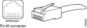
Ethernet Port (NIC 1 and NIC 2)
The CSACS 1120 Series appliance comes with two integrated dual-port Ethernet controllers. These controllers provide an interface for connecting to 10-Mb/s, 100-Mb/s, or 1000-Mb/s networks and provide full-duplex (FDX) capability, which enables simultaneous transmission and reception of data on the Ethernet LAN.
To access the Ethernet port, connect a Category 3, 4, 5, 5E, or 6 unshielded twisted-pair (UTP) cable to the RJ-45 connector on the back of the appliance.
Table 1-3 describes the UTP cable Categories.
Ethernet Port Connector
Figure 1-7 shows the Ethernet RJ-45 port and plug.
Figure 1-7 RJ-45 Port and Plug
Table 1-4 lists and describes the RJ-45 pin signals used on the connector.
Serial (Console) Port
The CSACS 1120 Series appliance has one standard serial (console) port. Use the configuration or setup utility program to change the port address assignments.
Note
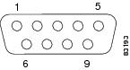
Serial (Console) Port Connector
The CSACS 1120 Series appliance has one serial port connector located on the back panel of the appliance.
Figure 1-8 shows the pin number assignments for the 9-pin, male D-shell serial port connector located on the back panel of the appliance. These pin number assignments conform to industry standards.
Figure 1-8 Serial Port Connector
Table 1-5 lists and describes the serial (console) port pinout.
Environmental Monitoring
The CSACS 1120 Series appliance has protection circuits that monitor and detect overcurrent, overvoltage, and overtemperature conditions inside the appliance. If the power supply shuts down, or latches off, an AC cycle switches off for 15 seconds and switches on for 1 second to reset the power supply.
This section contains:
•
Overcurrent Protection (OCP)
The power supply shuts down and latches off after an overcurrent condition occurs. This latch is cleared by an AC power interruption.
Note
Overvoltage Protection (OVP)
The power supply shuts down and latches off after an overvoltage condition occurs. This latch is cleared by an AC power interruption.
Overtemperature Protection (OTP)
The power supply is protected against overtemperature conditions caused by the loss of fan cooling or excessive ambient temperature. In an OTP condition, the power supply will shut down. When the power supply temperature drops to the rated safety limit, the power supply restores power automatically.
Regulatory Compliance
For regulatory compliance and safety information, see Regulatory Compliance and Safety Information for the Cisco 1120 Secure Access Control Server 4.2. This document is available online at Cisco.com:
For more information, see Obtaining Documentation and Submitting a Service Request, page -xv.