-
Installation and Setup Guide for Cisco Secure ACS Solution Engine 4.0
-
Cisco 90-Day Limited Hardware Warranty Terms
-
Preface
-
Cisco Secure ACS Solution Engine Overview
-
Preparing for Installation
-
Installing and Configuring Cisco Secure ACS Solution Engine 4.0
-
Administering Cisco Secure ACS Solution Engine
-
Upgrading and Migrating to Cisco Secure ACS Solution Engine
-
Technical Specifications for the Quanta (1112) Version
-
Technical Specifications for the Quanta (1113) Version
-
Windows Service Advisement
-
Command Reference
-
Index
-
 Feedback
Table Of Contents
Cisco Secure ACS Solution Engine Overview
Solution Engine Specifications for the Quanta (1112) Version Platform
Front Panel Features for the Quanta (1112) Version
Back Panel Features for the Quanta (1112) Version
Solution Engine Specifications for the Quanta (1113) Version Platform
Front Panel Features for the Quanta (1113) Version
Back Panel Features for the Quanta (1113) Version
Cisco Secure ACS Solution Engine Overview
System Description
Cisco Secure ACS Solution Engine (ACS SE) is a highly scalable, rack-mounted, dedicated platform that serves as a high-performance access control server supporting centralized Remote Access Dial-In User Service (RADIUS) and Terminal Access Controller Access Control System (TACACS+). ACS SE controls the authentication, authorization, and accounting (AAA) of users accessing corporate resources through the network.
You use ACS SE to control who can access the network, to authorize what types of network services are available for particular users or groups of users, and to keep an accounting record of all user actions in the network. The appliance supports access control and accounting for dial-up access servers, firewalls and VPNs, Voice-over-IP solutions, content networking, and switched and wireless local area networks (LANs and WLANs). In addition, you can use the same AAA framework, via TACACS+, to manage administrative roles and groups and to control how network administrators change, access, and configure the network internally.
ACS SE provides almost the same set of features and functions as in the Cisco Secure ACS for Windows Server (the software product) in a dedicated, security hardened, application-specific, appliance packaging. ACS SE includes additional features specific to operating and managing the ACS appliance. See Release Notes for Cisco Secure ACS Solution Engine for the new features in this release.
To ensure a highly secure posture, ACS SE:
•
Runs only the necessary services of the underlying hardened Windows operating system. (See Appendix C, "Windows Service Advisement," for details on the hardening.)
•
•
•
•
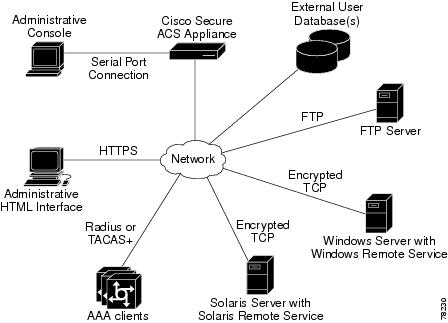
Figure 1-1 shows the ACS SE operating context.
Figure 1-1 ACS SE Context Diagram
The administrative console in the context diagram represents any data terminal equipment (DTE) capable of supporting administrative connection via a serial port connection and is generally referred to as a console in this guide.
For more detailed information on ACS SE features and capabilities, see the User Guide for Cisco Secure ACS Solution Engine and the Release Notes for Cisco Secure ACS Solution Engine.
ACS SE Hardware Description
ACS SE is a rack-mountable 1U box. The sections below describe the following hardware devices:
•
•
Solution Engine Specifications for the Quanta (1112) Version Platform
The ACS SE on the Quanta (1112) platform has the following specifications:
•
•
•
•
•
•
The parallel port, video, keyboard, and mouse controllers are not used.
Technical specifications for the Quanta (1112) version are detailed in Appendix A, "Technical Specifications for the Quanta (1112) Version."
This section contains the following sections and subsections:
•
•
Front Panel Features for the Quanta (1112) Version
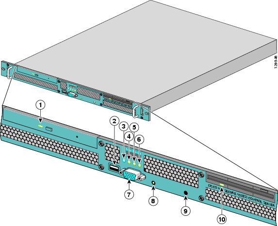
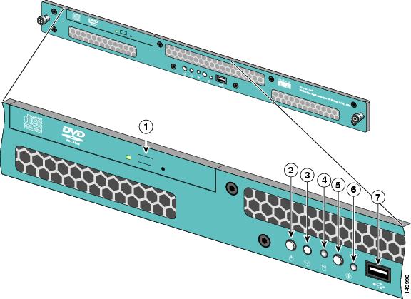
The ACS SE front panel on the Quanta (1112) version contains switches, indicators, and the CD-ROM drive. Figure 1-2 shows the front panel switches and LED indicators. The functions of the switches and LED indicators are described in the table below the illustration.
Figure 1-2 Front Panel Switches and Indicators
The following table describes the callouts in Figure 1-2.
Back Panel Features for the Quanta (1112) Version
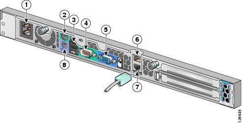
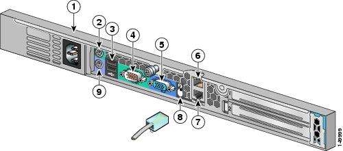
The back panel for the Quanta (1112) versions contains the AC power receptacle, Ethernet connectors, indicator LEDs, and a serial port. Figure 1-3 shows the back-panel features.
Figure 1-3 Back Panel Features for the Quanta (1112) Version
The following table describes the callouts in Figure 1-3.
AC power receptacle
Mouse connector (not supported). Do not use.
USB connector 1 (not supported). Do not use.
Serial connector (see Figure 1-4)
Video connector (not supported). Do not use.
RJ-45 Fast Ethernet connector with 10/100/1000-Mbit/s operation for NIC 2
RJ-45 Fast Ethernet connector with 10/100/1000-Mbit/s operation for NIC 1
Keyboard connector (not supported). Do not use.
Serial Port
The integrated serial port on the back panel of the appliance uses a 9-pin D-subminiature connector.
Serial Port Connector
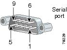
If you reconfigure your hardware, you may need information regarding the pin number and signal for the serial port connector. Figure 1-4 illustrates the pin numbers for the serial port connector, and defines the pin assignments and interface signals for the serial port connector. (Pin numbering proceeds bottom to top and right to left, as illustrated.)
Figure 1-4 Pin Numbers for the Serial Port Connector
Ethernet Connectors
Your system has two integrated 10/100/1000-megabit-per-second (Mbps) Ethernet connectors. ACS SE supports the operation of either Ethernet connector, but not both connectors. Each Ethernet connector provides all the functions of a network expansion card and supports the 10BASE-T, 100BASE-TX, and 1000BASE-TX Ethernet standards.
Each NIC is configured to automatically detect the speed and duplex mode of the network.
Note
Network Cable Requirements
The Ethernet connectors are designed for attaching an unshielded twisted pair (UTP) Ethernet cable equipped with standard RJ-45 compatible plugs. Press one end of the UTP cable into the Ethernet connector until the plug snaps securely into place. Connect the other end of the cable to an RJ-45 port on a hub or other device, depending on your network configuration. Observe the following cabling restrictions for 10BASE-T, 100BASE-TX, and 1000BASE-TX networks:
•
•
•
Solution Engine Specifications for the Quanta (1113) Version Platform
The ACS SE on the Quanta (1113) platform has the following specifications:
•
•
•
•
•
Technical specifications are detailed in Appendix B, "Technical Specifications for the Quanta (1113) Version."
This section contains the following sections and subsections:
•
•
Front Panel Features for the Quanta (1113) Version
The ACS SE front panel on the Quanta (1113) version contains switches, indicators, and the CD-ROM drive. Figure 1-5 shows the front panel switches and LED indicators. The functions of the switches and LED indicators are described in the table below the illustration.
Figure 1-5 Front Panel Switches and Indicators for the Quanta (1113) Version
The following table describes the callouts in Figure 1-5.
Back Panel Features for the Quanta (1113) Version
The back panel for the Quanta (1113) version contains the AC power receptacle, Ethernet connectors, indicator LEDs, and a serial port. Figure 1-6 shows the back-panel features.
Figure 1-6 Back Panel Features for the Quanta (1113) Version
The following table describes the callouts in Figure 1-6.
AC power receptacle
Mouse connector (not supported). Do not use.
USB connectors (not supported). Do not use.
Serial connector (see Figure 1-4)
Video connector (not supported). Do not use.
RJ-45 Fast Ethernet connector with 10/100/1000-Mbit/s operation for NIC 2
RJ-45 Fast Ethernet connector with 10/100/1000-Mbit/s operation for NIC 1
Unit Identification Button and LED. When the Unit Identification Button on the front panel is pressed, this causes the Unit Identification Button on the back panel to flash blue. To turn off the Unit Identification indicator on the back panel, push the Unit Identification button.
Keyboard connector
Serial Port
The integrated serial port on the back panel of the appliance uses a 9-pin, D-subminiature connector.
Serial Port Connector
If you reconfigure your hardware, you may need information regarding the pin number and signal for the serial port connector. Figure 1-7 illustrates the pin numbers for the serial port connector, and defines the pin assignments and interface signals for the serial port connector. (Pin numbering proceeds bottom to top and right to left, as illustrated.)
Figure 1-7 Pin Numbers for the Serial Port Connector
Ethernet Connectors
Your Quanta (1113) system has two integrated 10/100/1000-megabit-per-second (Mbps) Ethernet connectors. ACS SE supports the operation of either Ethernet connector, but not both connectors. Each Ethernet connector provides all the functions of a network expansion card and supports the 10BASE-T, 100BASE-TX, and 1000BASE-TX Ethernet standards.
Each NIC is configured to automatically detect the speed and duplex mode of the network.
Network Cable Requirements
The Ethernet connectors are designed for attaching an unshielded twisted pair (UTP) Ethernet cable equipped with standard RJ-45 compatible plugs. Press one end of the UTP cable into the Ethernet connector until the plug snaps securely into place. Connect the other end of the cable to an RJ-45 port on a hub or other device, depending on your network configuration. Observe the following cabling restrictions for 10BASE-T, 100BASE-TX, and 1000BASE-TX networks:
•
•
•