-
Installation and Setup Guide for Cisco Secure ACS Solution Engine 4.0
-
Cisco 90-Day Limited Hardware Warranty Terms
-
Preface
-
Cisco Secure ACS Solution Engine Overview
-
Preparing for Installation
-
Installing and Configuring Cisco Secure ACS Solution Engine 4.0
-
Administering Cisco Secure ACS Solution Engine
-
Upgrading and Migrating to Cisco Secure ACS Solution Engine
-
Technical Specifications for the Quanta (1112) Version
-
Technical Specifications for the Quanta (1113) Version
-
Windows Service Advisement
-
Command Reference
-
Index
-
 Feedback
Table Of Contents
Installing and Configuring Cisco Secure ACS Solution Engine 4.0
Installing the Quanta (1112) ACS SE in a Rack
Installing the Quanta (1113) ACS SE in a Rack
Attaching the Chassis Rail Mount
Connecting to the AC Power Source
Establishing a Serial Console Connection
Verifying the Initial Configuration
Installing and Configuring Cisco Secure ACS Solution Engine 4.0
This chapter describes how to install and initially configure Cisco Secure ACS Solution Engine (ACS SE) 4.0. It contains the following sections:
•
Installing the Quanta (1112) ACS SE in a Rack
•
•
•
Note
Installation Quick Reference
Table 3-1 provides a high-level overview of the installation and initial configuration process. Following installation and initial configuration, see the User Guide for Cisco Secure ACS Solution Engine for information on how to use a browser and the web interface to fully configure your ACS SE to provide the AAA services that you want from this installation.
Table 3-1 Quick Reference
Use the rack mount kit to install the ACS SE in a rack.
Installing the Quanta (1112) ACS SE in a Rack
Connect the ACS SE to an AC power source.
Connect network and console cables.
Perform initial configuration of the ACS SE
Verify initial configuration
Configure ACS SE to provide AAA services
Installing the Quanta (1112) ACS SE in a Rack
This section provides instructions for installing the ACS SE Quanta (1112) version in a rack. The rack must be properly secured to the floor, ceiling, or upper wall, and where applicable, to adjacent racks. The rack should be secured by using floor and wall fasteners, and bracing specified by industry standards.
Before installing the ACS SE in a rack, read Preparing Your Site for Installation, page 2-5, to familiarize yourself with the proper site and environmental conditions. Failure to read and follow these guidelines could lead to an unsuccessful installation and possible damage to the system and components.
When installing and servicing the ACS SE:
•
•
–
–
–
•
•
•
•
See Precautions for Rack-Mounting, page 2-8, for additional safety information on rack installation.
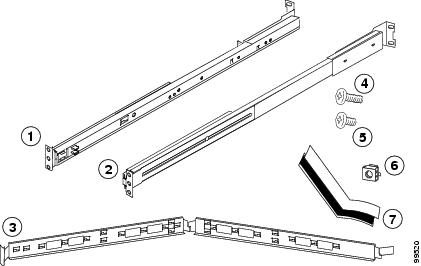
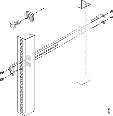
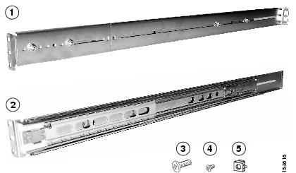
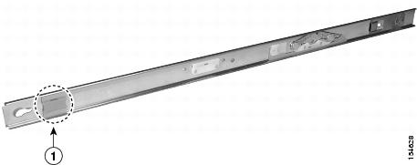
The server can be installed in a system 1U rack. The rack rail components are (numbers in parentheses refer to Figure 3-1):
•
•
•
–
–
–
–
Figure 3-1 Rack Rail Components
To install the Quanta (1112) ACS SE in a rack:
Step 1
a.
b.
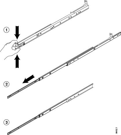
Figure 3-2 Removing the Server Rail
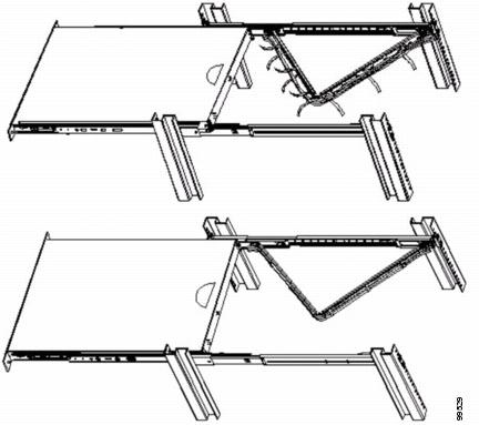
c.
Figure 3-3 Telescoping the Rail
Note
d.
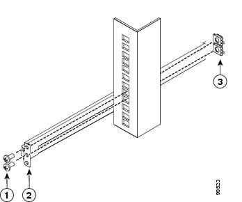
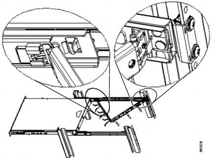
Figure 3-4 Attaching Front Rail to the Rack
Note
e.
Figure 3-5 Attaching Back Rail to Rack
f.
g.
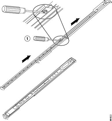
Figure 3-6 Attaching Screws to Telescopic Rail
Note
Step 2
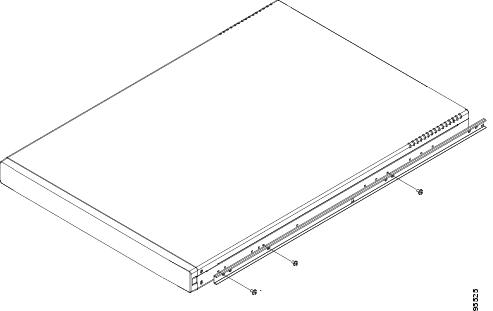
a.
Figure 3-7 Attaching Chassis to Rail
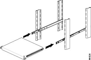
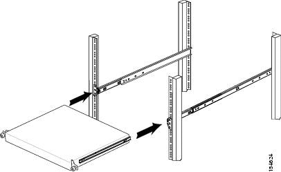
b.
Figure 3-8 Sliding Chassis onto Rack
c.
d.
Figure 3-9 Attaching Velcro to Management Arm
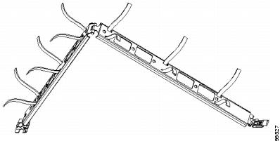
e.
Figure 3-10 Attaching Management Arm
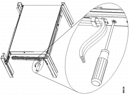
f.
Figure 3-11 Installing Cable in Management Arm
g.
Figure 3-12 Fastening the Server into the Rack
Warning
Installing the Quanta (1113) ACS SE in a Rack
Before installing the Quanta (1113) ACS SE in a rack, read Preparing Your Site for Installation, page 2-5 to familiarize yourself with the proper site and environmental conditions. Failure to read and follow these guidelines could lead to an unsuccessful installation and possible damage to the system and components. Perform the steps below when installing and servicing the WLSE.
The rack must be properly secured to the floor, to the ceiling or upper wall, and where applicable, to adjacent racks. The rack should be secured using floor and wall fasteners and bracing specified or approved by the rack manufacturer or by industry standards.
When installing and servicing the ACS SE:
•
•
–
–
–
•
•
•
•
See Precautions for Rack-Mounting, page 2-8 for additional safety information on rack installation.
The server can be installed in a system 1U rack. The rack rail components are as follows (numbers in parentheses refer to Figure 3-13):
•
•
–
–
–
Figure 3-13 Rack Rail Components
To install the ACS SE 1113 (Quanta 1113) a rack, perform these steps as explained in the following sections:
1.
2.
3.
Attaching the Chassis Rail Mount
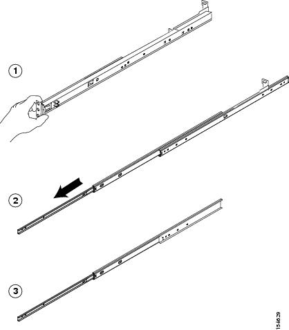
You must first remove the chassis rail mount section from the server rail and attach it to the chassis as shown in the following steps.
Procedure
Step 1
Figure 3-14 Removing the Chassis Rail Mount
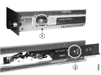
Step 2
Figure 3-15 Sliding the Chassis Rail Mount Release Tab
Step 3
Figure 3-16 Positioning Chassis Rail Mount on Chassis
Step 4
Figure 3-17 Attaching Chassis Rail Mount to Chassis
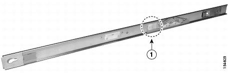
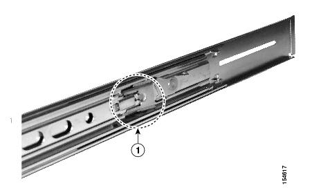
Figure 3-18 shows the chassis rail mount locked into place.
Figure 3-18 Chassis Rail Mount in Locked Position
Attaching the Server Rail
Now that you have mounted the chassis rail mount, retract the server rail that you previously extended and then attach it to the rack. If you have already retracted the server rail, go to step 2.
Procedure
Step 1
Figure 3-19 Retracting the Server Rail
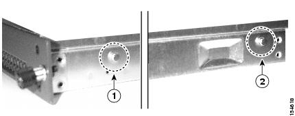
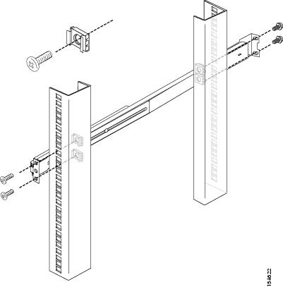
Step 2
–
–
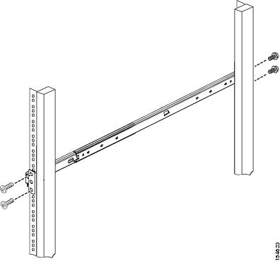
Figure 3-20 Attaching Rail to a Square-Peg Rack
Figure 3-21 Attaching Rail to a Circular-Peg Rack
Step 3
Note
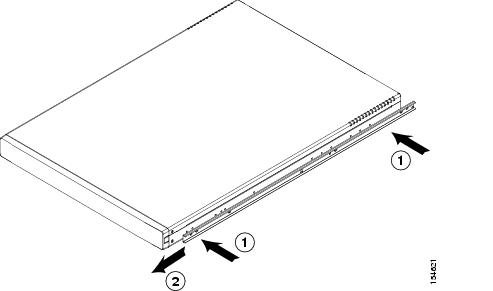
Sliding Chassis On the Rack
Step 1
Figure 3-22 Sliding the Chassis Rail Mount Extended Tab
Step 2
Figure 3-23 Sliding Chassis onto Rack
Slide the chassis back and forth several times. Fasten with all the screws.
Warning
Connecting to the AC Power Source
Warning
Connect the AC power receptacle to the AC power source with the provided power cable.
Connecting Cables
Use unshielded twisted-pair (UTP,) copper-wire Ethernet cable, with standard RJ-45-compatible plugs, to connect the ACS SE to the network.
To connect the cables:
Step 1
Step 2
Warning
Initial Configuration
The first three steps of the four steps required to configure the ACS are documented in this manual:
•
•
Note
Establishing a Serial Console Connection
Before you can perform the initial configuration of ACS SE, you must establish a serial console connection to it. This procedure requires a PC, two DB-9 to RJ-45 adapters (provided), an RJ-45 cable (provided), and terminal emulation communication software (Hyper Terminal or equivalent).
To establish a serial console connection:
Note
Step 1
a.
b.
c.
Tip
Step 2
Tip
Step 3
•
•
•
•
•
Result: The login: prompt appears.
Configuring ACS SE
You must configure the ACS SE when you boot the system for the first time, and whenever you re-image the system.
Before you begin to configure the solution engine, you should have the following information:
•
•
•
•
•
•
•
To configure the ACS SE:
Step 1
Note
Step 2
Cisco Secure ACS: [version number]Appliance Management Software: [version number]Appliance Base Image: [version number]CSA build [version number]: (Patch: [version number])Status: Appliance is functioning properlyThe ACS Appliance has not been configured. Logon as "Administrator" with password "setup" to configure appliance.Step 3
Note
Result: The system displays the password: prompt.
Step 4
Note
Result: The system displays the following message on the console:
Initialize Appliance.Machine will be rebooted after initialization.Entering Ctrl-C before setting appliance name will shutdown the applianceStep 5
Tip
Result: The system displays the following message on the console:
ACS Appliance name is set to xxx.Step 6
Result: The system displays the following message on the console:
DNS name is set to xxx.com.You need to set the administrator account name and password.Step 7
Tip
Step 8
Note
Step 9
Result: The system displays the following message on the console:
Password is set successfully.Administrator name is set to xxx.Step 10
Please enter the Encryption Password for the Configuration Store.Please note this is different from the administrator account,it is used to encrypt the Database.Type the new database password and press Enter.
Note
Step 11
Result: The system displays the following message on the console:
Password is set successfully.Step 12
Note
Note
Step 13
No change to the configuration.Accept network setting [Yes]a.
b.
c.
d.
Note
Result: The system displays the new configuration information followed by this message:
IP Address is reconfigured.e.
Result: The system displays the following message:
New ip address is set.Default gateway is set to xx.xx.xx.xxDNS servers are set to: xx.xx.xx.xx xx.xx.xx.xx.f.
Tip
g.
Result: If successful, the system displays the ping statistics. The system displays the prompt: Test network connectivity [Yes]:.
h.
Tip
Step 14
Result: The system displays the following message on the console:
Current Date Time Setting:Time Zone: (GMT -xx:xx) XXX TimeDate and Time: mm/dd/yyyyNTP Server(s): NTP Synchronization Disabled.Step 15
Result: The system displays a numbered list of time zones.
Step 16
Result: The system displays the new time zone.
Step 17
•
•
Tip
Result: The system displays a confirmation message reflecting your choice.
Step 18
Step 19
Result: The system displays the following message on the console:
Initial configuration is successful. Appliance will now reboot.The system reboots.
Verifying the Initial Configuration
To verify that you have correctly completed the ACS SE initial configuration:
Before You Begin
Establish a serial console connection to the ACS SE. For details, see Establishing a Serial Console Connection.
Step 1
Result: When the systems finish booting, a login: prompt appears on the console.
Step 2
Result: The password prompt appears.
Step 3
Result: The system prompt appears.
Step 4
Result: The system displays status information.
Step 5
Next Steps
After you have successfully performed the procedures in this guide, your ACS SE is installed and initially configured. The next step is to use a browser and the web interface to fully configure your ACS SE to provide the AAA services that you want from this installation. The HTML address is in the following format: HTTP//[ip address]:2002, where ip address is the address that you assign during configuration.
For information on setting up user, group, network, and other parameters, see the User Guide for Cisco Secure ACS Solution Engine.
Note