Table Of Contents
Finding Feature Information in This Module
Prerequisites for Implementing Tunnels
Restrictions for Implementing Tunnels
Information About Implementing Tunnels
Tunneling Versus Encapsulation
Definition of Tunneling Types by OSI Layer
GRE Tunnel IP Source and Destination VRF Membership
GRE/CLNS Tunnel Support for IPv4 and IPv6 Packets
GRE/IPv4 Tunnel Support for IPv6 Traffic
IPv6 Manually Configured Tunnels
Automatic IPv4-Compatible IPv6 Tunnels
Rate-Based Satellite Control Protocol Tunnels
Configuring GRE Tunnel IP Source and Destination VRF Membership
Restrictions for GRE Tunnel IP Source and Destination VRF Membership
Configuring GRE/CLNS CTunnels to Carry IPv4 and IPv6 Packets
Tunnels for IPv4 and IPv6 Packets over CLNS Networks
Configuring Manual IPv6 Tunnels
Configuring IPv4-Compatible IPv6 Tunnels
Verifying Tunnel Configuration and Operation
Verifying RBSCP Tunnel Configuration and Operation
Verifying That the RBSCP Tunnel Is Active
Configuration Examples for Implementing Tunnels
Example: Configuring GRE/IPv4 Tunnels
Example: Configuring GRE/IPv6 Tunnels
Example: Configuring GRE Tunnel IP Source and Destination VRF Membership
Example: Routing Two AppleTalk Networks Across an IP-Only Backbone
Example: Routing a Private IP Network and a Novell Network Across a Public Service Provider
Example: Configuring a CTunnel
Example: Configuring GRE/CLNS CTunnels to Carry IPv4 and IPv6 Packets
Example: Configuring Manual IPv6 Tunnels
Example: Configuring 6to4 Tunnels
Example: Configuring IPv4-Compatible IPv6 Tunnels
Example: Configuring ISATAP Tunnels
Example: Configuring the RBSCP Tunnel
Example: Configuring Routing for the RBSCP Tunnel
Example: Configuring QoS Options on Tunnel Interfaces
Example: Configuring EoMPLS over GRE
Feature Information for Implementing Tunnels
Implementing Tunnels
First Published: May 2, 2005
Last Updated: July 22, 2010This module describes the various types of tunneling techniques available using Cisco IOS software. Configuration details and examples are provided for the tunnel types that use physical or virtual interfaces. Many tunneling techniques are implemented using technology-specific commands, and links are provided to the appropriate technology modules.
Tunneling provides a way to encapsulate arbitrary packets inside a transport protocol. Tunnels are implemented as a virtual interface to provide a simple interface for configuration. The tunnel interface is not tied to specific "passenger" or "transport" protocols, but rather is an architecture to provide the services necessary to implement any standard point-to-point encapsulation scheme.
NoteCisco ASR 1000 Series Routers support virtual routing and forwarding (VRF)-aware, and generic routing encapsulation (GRE) tunnel keepalive features.
Finding Feature Information in This Module
Your software release may not support all the features documented in this module. For the latest feature information and caveats, see the release notes for your platform and software release. To find information about the features documented in this module, and to see a list of the releases in which each feature is supported, see the "Feature Information for Implementing Tunnels" section.
Use Cisco Feature Navigator to find information about platform support and Cisco software image support. To access Cisco Feature Navigator, go to http://www.cisco.com/go/cfn. An account on Cisco.com is not required.
Contents
•
•
•
•
•
Prerequisites for Implementing Tunnels
This module assumes that you are running Cisco IOS Release 12.2 software or a later release.
Restrictions for Implementing Tunnels
•
•
•
•
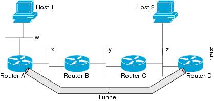
For example, in the topology shown in Figure 1, packets from Host 1 will appear to travel across networks w, t, and z to get to Host 2 instead of taking the path w, x, y, and z because the tunnel hop count appears shorter. In fact, the packets going through the tunnel will still be traveling across Router A, B, and C, but they must also travel to Router D before coming back to Router C.Figure 1 Tunnel Precautions: Hop Counts
•
–
–
–
When you have recursive routing to the tunnel destination, the following error is displayed:
%TUN-RECURDOWN Interface Tunnel 0temporarily disabled due to recursive routing
NoteInformation About Implementing Tunnels
•
•
•
•
•
•
•
•
•
Tunneling Versus Encapsulation
To understand how tunnels work, it is important to distinguish between the concepts of encapsulation and tunneling. Encapsulation is the process of adding headers to data at each layer of a particular protocol stack. The Open Systems Interconnection (OSI) reference model describes the functions of a network as seven layers stacked on top of each other. When data has to be sent from one host (a PC for example) on a network to another host, the process of encapsulation is used to add a header in front of the data at each layer of the protocol stack in descending order. The header must contain a data field that indicates the type of data encapsulated at the layer immediately above the current layer. As the packet ascends the protocol stack on the receiving side of the network, each encapsulation header is removed in the reverse order.
Tunneling encapsulates data packets from one protocol inside a different protocol and transports the data packets unchanged across a foreign network. Unlike encapsulation, tunneling allows a lower-layer protocol, or same-layer protocol, to be carried through the tunnel. A tunnel interface is a virtual (or logical) interface. For more details on other types of virtual interfaces, see the "Configuring Virtual Interfaces" module. Although many different types of tunnels have been created to solve different network problems, tunneling consists of three main components:
•
•
•
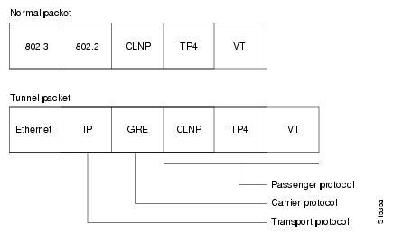
Figure 2 illustrates IP tunneling terminology and concepts.
Figure 2 IP Tunneling Terminology and Concepts
To understand the process of tunneling, consider connecting two AppleTalk networks with a non-AppleTalk backbone, such as IP. The relatively high bandwidth consumed by the broadcasting of Routing Table Maintenance Protocol (RTMP) data packets can severely hamper the backbone's network performance. This problem can be solved by tunneling AppleTalk through a foreign protocol, such as IP. Tunneling encapsulates an AppleTalk packet inside the foreign protocol packet (AppleTalk inside GRE inside IP), which is then sent across the backbone to a destination router. The destination router then removes the encapsulation from the AppleTalk packet and routes the packet.
Definition of Tunneling Types by OSI Layer
Tunnels are used by many different technologies to solve different network challenges, and the resulting variety of tunnel types makes it difficult to determine which tunneling technique to use. The different carrier protocols can be grouped according to the OSI layer model. Table 1 shows the different carrier protocols grouped by OSI layer. Below the table, each carrier protocol is defined, and if the tunnel configuration is not covered within this module, a link to the appropriate module is included.
BSTUN
A Block Serial Tunnel (BSTUN) enables support for devices using the Bisync data-link protocol. This protocol enables enterprises to transport Bisync traffic over the same network that supports their Systems Network Architecture (SNA) and multiprotocol traffic, eliminating the need for separate Bisync facilities.
For more details about configuring BSTUN, see the "Configuring Serial Tunnel and Block Serial Tunnel" module in the Cisco IOS Bridging and IBM Networking Configuration Guide.
CLNS
The ISO Connectionless Network Service (CLNS) protocol is a standard for the network layer of the OSI model. IP traffic can be transported over CLNS; for instance, on the data communications channel (DCC) of a SONET ring. An IP over CLNS tunnel (CTunnel) is a virtual interface that enhances interactions with CLNS networks, allowing IP packets to be tunneled through the Connectionless Network Protocol (CLNP) to preserve TCP/IP services. CLNS can also be used as a transport protocol with GRE as a carrier protocol (GRE/CLNS), carrying both IPv4 and IPv6 packets.
DLSw+
Data-link switching plus (DLSw+) is Cisco's implementation of the DLSw standard for Systems Network Architecture (SNA) and NetBIOS devices, and it supports several additional features and enhancements. DLSw+ is a means of transporting SNA and NetBIOS traffic over a campus or WAN. The end systems can attach to the network over Token Ring, Ethernet, Synchronous Data Link Control (SDLC), Qualified Logical Link Control (QLLC), or Fiber Distributed Data Interface (FDDI). DLSw+ switches between diverse media and locally terminates the data links, keeping acknowledgments, keepalives, and polling off the WAN.
For more details about configuring DLSw+, see the "Configuring Data-Link Switching Plus" module in the Cisco IOS Bridging and IBM Networking Configuration Guide.
GRE
Generic routing encapsulation (GRE) is defined in RFC 2784. GRE is a carrier protocol that can be used with a variety of underlying transport protocols, and GRE can carry a variety of passenger protocols. RFC 2784 also covers the use of GRE with IPv4 as the transport protocol and the passenger protocol. Cisco IOS software supports GRE as the carrier protocol with many combinations of passenger and transport protocols.
For more details about GRE, see the "Generic Routing Encapsulation" section.
IP-in-IP
IP-in-IP is a Layer 3 tunneling protocol—defined in RFC 2003—that alters the normal routing of an IP packet by encapsulating it within another IP header. The encapsulating header specifies the address of a router that would not ordinarily be selected as a next-hop router on the basis of the real destination address of the packet. The intermediate node decapsulates the packet, which is then routed to the destination as usual.
IPsec
In simple terms, IP Security (IPsec) provides secure tunnels between two peers, such as two routers. You define which packets are considered sensitive and should be sent through these secure tunnels, and you define the parameters that should be used to protect these packets by specifying characteristics of these tunnels. IPsec peers set up a secure tunnel and encrypt the packets that traverse the tunnel to the remote peer.
IPsec also works with the GRE and IP-in-IP, L2F, L2TP, and DLSw+ tunneling protocols; however, multipoint tunnels are not supported. Other Layer 3 tunneling protocols may not be supported for use with IPsec.
For more details about configuring IPSec, see the "Configuring Security for VPNs with IPSec" module in the Cisco IOS Security Configuration Guide.
IPv6
IP version 6 (IPv6) is a new version of the Internet Protocol based on and designed as the successor to IP version 4. IPv6 adds a much larger address space—128 bits—and improvements such as a simplified main header and extension headers. IPv6 is described initially in RFC 2460, Internet Protocol, Version 6 (IPv6). The use of IPv6 as a carrier protocol is described in RFC 2473, Generic Packet Tunneling in IPv6 Specification.
L2F
Layer 2 Forwarding (L2F) tunneling is used in virtual private dialup networks (VPDNs). A VPDN allows separate and autonomous protocol domains to share common access infrastructure including modems, access servers, and ISDN routers by the tunneling of link-level (Layer 2) frames. Typical L2F tunneling use includes Internet service providers (ISPs) or other access service creating virtual tunnels to link to remote customer sites or remote users with corporate intranet or extranet networks.
L2TP
Layer 2 Tunneling Protocol (L2TP) is an open standard created by the Internet Engineering Task Force (IETF) that uses the best features of L2F and Point-to-Point Tunneling Protocol (PPTP). L2TP is designed to secure the transmission of IP packets across uncontrolled and untrusted network domains, and it is an important component of Virtual Private Networks (VPNs). VPNs extend remote access to users over a shared infrastructure while maintaining the same security and management policies as a private network.
For more details about configuring L2TP, see the Cisco IOS Dial Technologies Configuration Guide.
MPLS
Multiprotocol Label Switching (MPLS) is a high-performance packet forwarding technology that integrates the performance and traffic management capabilities of data-link-layer (Layer 2) switching with the scalability, flexibility, and performance of network-layer (Layer 3) routing. The MPLS architecture has been designed to allow data to be transferred over any combination of Layer 2 technologies, to support all Layer 3 protocols, and to scale. Using CEF, MPLS can efficiently enable the delivery of IP services over an ATM switched network. MPLS is an integration of Layer 2 and Layer 3 technologies. By making traditional Layer 2 features available to Layer 3, MPLS enables traffic engineering.
For more details about how MPLS traffic engineering uses tunnels, see the Cisco IOS Multiprotocol Label Switching Configuration Guide.
PPPoA
PPP over ATM (PPPoA) is mainly implemented as part of Asymmetric Digital Subscriber Line (ADSL). It relies on RFC 1483, operating in either Logical Link Control-Subnetwork Access Protocol (LLC-SNAP) or VC-Mux mode. A customer premises equipment (CPE) device encapsulates the PPP session based on this RFC for transport across the ADSL loop and the digital subscriber line access multiplexer (DSLAM).
PPPoE
RFC 2516 defines PPP over Ethernet (PPPoE) as providing the ability to connect a network of hosts over a simple bridging access device to a remote access concentrator or aggregation concentrator. As customers deploy ADSL, they must support PPP-style authentication and authorization over a large installed base of legacy bridging customer premises equipment (CPE). Using a form of tunneling encapsulation, PPPoE allows each host to use its own PPP stack, thus presenting the user with a familiar user interface. Access control, billing, and type of service (ToS) can be done on a per-user, rather than a per-site, basis.
For more details about configuring PPPoE, see the Cisco IOS Broadband Access Aggregation and DSL Configuration Guide.
PPTP
Point-to-Point Tunneling Protocol (PPTP) is a network protocol that enables the secure transfer of data from a remote client enterprise server by creating a VPN across TCP/IP data networks. PPTP supports on-demand, multiprotocol virtual private networking over public networks such as the Internet.
RBSCP
Rate-Based Satellite Control Protocol (RBSCP) was designed for wireless or long-distance delay links with high error rates, such as satellite links. Using tunnels, RBSCP can improve the performance of certain IP protocols, such as TCP and IP Security (IPsec), over satellite links without breaking the end-to-end model.
SSL Tunnels
Secure Socket Layer (SSL) is designed to make use of TCP sessions to provide a reliable end-to-end secure service. The main role of SSL is to provide security for web traffic. Security includes confidentiality, message integrity, and authentication. SSL achieves these elements of security through the use of cryptography, digital signatures, and certificates. SSL protects confidential information through the use of cryptography. Sensitive data is encrypted across public networks to achieve a level of confidentiality.
SSL is implemented using the Cisco Application and Content Networking System (ACNS). For more details about configuring SSL, see the latest Cisco ACNS Software Deployment and Configuration Guide.
STUN
Cisco's Serial Tunneling (STUN) implementation allows Synchronous Data Link Control (SDLC) protocol devices and High-Level Data Link Control (HDLC) devices to connect to one another through a multiprotocol internetwork rather than through a direct serial link. STUN encapsulates SDLC frames in either the TCP/IP or the HDLC protocol. STUN provides a straight passthrough of all SDLC traffic (including control frames, such as Receiver Ready) end-to-end between Systems Network Architecture (SNA) devices.
For more details about configuring STUN, see the "Configuring Serial Tunnel and Block Serial Tunnel" module in the Cisco IOS Bridging and IBM Networking Configuration Guide.
UDLR Tunnels
Unidirectional link routing (UDLR) provides mechanisms for a router to emulate a bidirectional link to enable the routing of unicast and multicast packets over a physical unidirectional interface, such as a broadcast satellite link. However, there must be a back channel or other path between the routers that share a physical unidirectional link (UDL). A UDLR tunnel is a mechanism for unicast and multicast traffic; Internet Group Management Protocol (IGMP) UDLR is a related technology for multicast traffic.
For more details, see Cisco IOS IP Multicast Configuration Guide.
Benefits of Tunneling
The following are several situations in which tunneling (encapsulating traffic in another protocol) is useful:
•
•
•
•
Figure 3 Providing Workarounds for Networks with Limited Hop Counts
Tunnel ToS
Tunnel ToS allows you to tunnel your network traffic and group all your packets in the same specific ToS byte value. The ToS byte values and Time-to-Live (TTL) hop-count value can be set in the encapsulating IP header of tunnel packets for an IP tunnel interface on a router. The Tunnel ToS feature is supported for CEF, fast switching, and process switching.
The ToS and TTL byte values are defined in RFC 791. RFC 2474 and RFC 2780 obsolete the use of the ToS byte as defined in RFC 791. RFC 791 specifies that bits 6 and 7 of the ToS byte (the first two least significant bits) are reserved for future use and should be set to 0. The Tunnel ToS feature does not conform to this standard and allows you to set the whole ToS byte value, including bits 6 and 7, and to decide to which RFC standard the ToS byte of your packets should confirm.
Mobile IP Tunneling
New devices and business practices, such as PDAs and the next-generation of data-ready cellular phones and services, are driving interest in the ability of a user to roam while maintaining network connectivity. The requirement for data connectivity solutions for this group of users is very different than it is for the fixed dialup user or the stationary wired LAN user. Solutions need to accommodate the challenge of movement during a data session or conversation.
Mobile IP is a tunneling-based solution that takes advantage of the Cisco-created generic routing encapsulation (GRE) tunneling technology and simpler IP-in-IP tunneling protocol.
Mobile IP is comprises the following three components, as shown in Figure 4:
•
•
•
Figure 4 Mobile IP Components and Use of Tunneling
An MN is a node, for example, a PDA, a laptop computer, or a data-ready cellular phone, that can change its point of attachment from one network or subnet to another. This node can maintain ongoing communications while using only its home IP address. In Figure 4, the current location of the MN—a laptop computer—is shown in bold.
An HA is a router on the home network of the MN that maintains an association between the home IP address of the MN and its care-of address, which is the current location of the MN on a foreign or visited network. The HA redirects packets by tunneling them to the MN while it is away from home.
An FA is a router on a foreign network that assists the MN in informing its HA of its current care-of address. The FA detunnels packets that were tunneled by the HA and delivers them to the MN. The FA also acts as the default router for packets generated by the MN while it is connected to the foreign network.
The traffic destined for the MN is forwarded in a triangular manner. When a device on the Internet, called a correspondent node (CN), sends a packet to the MN, the packet is routed to the home network of the MN, the HA redirects the packet by tunneling to the care-of address (current location) of the MN on the foreign network, as shown in Figure 4. The FA receives the packet from the HA and forwards it locally to the MN. However, packets sent by the MN are routed directly to the CN.
For more details about configuring Mobile IP, see the Cisco IOS IP Mobility Configuration Guide.
Generic Routing Encapsulation
Generic routing encapsulation (GRE) is defined in RFC 2784. GRE is a carrier protocol that can be used with a variety of underlying transport protocols and that can carry a variety of passenger protocols. RFC 2784 also covers the use of GRE with IPv4 as the transport protocol and the passenger protocol. Cisco IOS software supports GRE as the carrier protocol with many combinations of passenger and transport protocols such as:
•
•
•
The following descriptions of GRE tunnels are included:
•
•
•
GRE Tunnel IP Source and Destination VRF Membership
GRE Tunnel IP Source and Destination VRF Membership allows you to configure the source and destination of a tunnel to belong to any VRF tables. A VRF table stores routing data for each VPN. The VRF table defines the VPN membership of a customer site attached to the network access server (NAS). Each VRF table comprises an IP routing table, a derived CEF table, and guidelines and routing protocol parameters that control the information that is included in the routing table.
Previously, Generic Routing Encapsulation (GRE) IP tunnels required the IP tunnel destination to be in the global routing table. The implementation of this feature allows you to configure a tunnel source and destination to belong to any VRF. As with existing GRE tunnels, the tunnel becomes disabled if no route to the tunnel destination is defined.
EoMPLS over GRE
Ethernet over multiprotocol label switching (EoMPLS) is a tunneling mechanism that allows you to tunnel Layer 2 traffic through a Layer 3 MPLS network. EoMPLS is also known as Layer 2 tunneling.
EoMPLS effectively facilitates the Layer 2 extension over long distances. EoMPLS over GRE helps to create the GRE tunnel as hardware-based switched, and with high performance that encapsulates EoMPLS frames within the GRE tunnel. The GRE connection is established between the two core routers, and then the MPLS LSP is tunneled over.
GRE encapsulation is used to define a packet that has some additional header information added to it prior to being forwarded. De-encapsulation is the process of removing the additional header information when the packet reaches the destination tunnel endpoint.
When a packet is forwarded through a GRE tunnel, two new headers are appended at the front of the packet and hence the context of the new payload changes. After encapsulation, what was originally the data payload and separate IP header is now known as the GRE payload. A GRE header is added to the packet to provide information on the protocol type and also a recalculated checksum. Also, a new IP header is added to the front of the GRE header. This IP header contains the destination IP address of the tunnel.
The GRE header is appended to the packet (IP, L2VPN, L3VPN, etc.) before entering the tunnel. All routers along the path that receive the encapsulated packet will use the new IP header to determine where to send the packet in an effort for it to reach the tunnel endpoint.
In the IP forwarding case on reaching the tunnel destination endpoint, the new IP header and GRE header are removed from the packet and the original IP header is then used to forward the packet to it's final destination.
In the EoMPLS over GRE cases, the new IP header and GRE header will be removed from the packet at the tunnel destination and the MPLS (VC or VPN) label will be used to forward the packets to the appropriate L2 attachment circuit or L3 VRF.
The following scenarios describe the L2VPN and L3VPN over GRE deployment on provider edge (PE) or provider (P) routers:
PE to PE GRE Tunnels
In the PE to PE GRE tunnels scenario, a customer does not generally transition any part of the core to MPLS but prefers to offer EoMPLS and basic MPLS VPN services. Hence, GRE tunneling of the MPLS labeled traffic is done between PEs. This is the most common scenario seen in various customers networks.
P to P GRE Tunnels
The P to P GRE tunnels scenario is one where MPLS has been enabled between PE and P routers, but the network core may have non-MPLS-aware routers or IP encryption boxes. In this scenario, GRE tunneling of the MPLS labeled packets is done between P routers.
PE to P GRE Tunnels
The PE to P GRE tunnels scenario demonstrates a network where the P to P nodes are MPLS-aware, while GRE tunneling is done between a PE to P non MPLS network segment.
The following features are required for the deployment of scenarios described above:
GRE Specific:
•
•
•
•
•
•
•
•
•
•
•
EoMPLS Specific:
•
•
•
•
•
•
•
MPLS-VPN Specific:
•
•
•
•
•
For a sample configuration sequence of EoMPLS over GRE, see Example: Configuring EoMPLS over GRE. For more details about EoMPLS over GRE, see Deploying and Configuring MPLS Virtual Private Networks In IP Tunnel Environments.
Multipoint GRE Tunneling
Enhanced multipoint GRE (mGRE) tunneling technology provides a Layer 3 (L3) transport mechanism for use in IP networks. This same dynamic Layer 3 tunneling transport can be used within IP networks to transport VPN traffic across service provider and enterprise networks, as well as to provide interoperability for packet transport between IP and MPLS VPNs. This feature provides support for RFC 2547, which defines the outsourcing of IP-backbone services for enterprise networks.
Multipoint tunnels use the Next Hop Resolution Protocol (NHRP) in the same way that a Frame Relay multipoint interface uses information obtained by the reverse ARP mechanism to learn the Layer 3 addresses of the remote data-link connection identifiers (DLCIs).
In Cisco IOS Release 12.2(8)T and later releases, CEF-switching over mGRE tunnels was introduced. Previously, only process switching was available for mGRE tunnels. CEF-switching over mGRE tunnels enables CEF switching of IP traffic to and from multipoint GRE tunnels. Tunnel traffic can be forwarded to a prefix through a tunnel destination when both the prefix and the tunnel destination are specified by the application.
GRE/CLNS Tunnel Support for IPv4 and IPv6 Packets
GRE tunneling of IPv4 and IPv6 packets through CLNS networks enables Cisco CLNS tunnels (CTunnels) to interoperate with networking equipment from other vendors. This feature provides compliance with RFC 3147.
The optional GRE services defined in header fields, such as checksums, keys, and sequencing, are not supported. Any packet that is received and requests such services will be dropped.
GRE/IPv4 Tunnel Support for IPv6 Traffic
IPv6 traffic can be carried over IPv4 generic routing encapsulation (GRE) tunnels using the standard GRE tunneling technique that is designed to provide the services necessary to implement any standard point-to-point encapsulation scheme. As in IPv6 manually configured tunnels, GRE tunnels are links between two points, with a separate tunnel for each link. The tunnels are not tied to a specific passenger or transport protocol, but in this case, IPv6 is the passenger protocol, GRE is the carrier protocol, and IPv4 is the transport protocol.
The primary use of GRE tunnels is for stable connections that require regular secure communication between two edge routers or between an edge router and an end system. The edge routers and the end systems must be dual-stack implementations.
GRE has a protocol field that identifies the passenger protocol. GRE tunnels allow IS-IS or IPv6 to be specified as a passenger protocol, allowing both IS-IS and IPv6 traffic to run over the same tunnel. If GRE did not have a protocol field, it would be impossible to distinguish whether the tunnel was carrying IS-IS or IPv6 packets. The GRE protocol field is why it is desirable that you tunnel IS-IS and IPv6 inside GRE.
Overlay Tunnels for IPv6
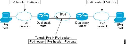
Overlay tunneling encapsulates IPv6 packets in IPv4 packets for delivery across an IPv4 infrastructure (a core network or the Internet). (See Figure 5.) By using overlay tunnels, you can communicate with isolated IPv6 networks without upgrading the IPv4 infrastructure between them. Overlay tunnels can be configured between border routers or between a border router and a host; however, both tunnel endpoints must support both the IPv4 and IPv6 protocol stacks. Cisco IOS IPv6 currently supports the following types of overlay tunneling mechanisms:
•
•
•
•
•
Figure 5 Overlay Tunnels
NoteUse Table 2 to help you determine which type of tunnel you want to configure to carry IPv6 packets over an IPv4 network.
Individual tunnel types are discussed in more detail in the following concepts, and we recommend that you review and understand the information on the specific tunnel type that you want to implement. When you are familiar with the type of tunnel you need, Table 3 provides a quick summary of the tunnel configuration parameters that you may find useful.
IPv6 Manually Configured Tunnels
A manually configured tunnel is equivalent to a permanent link between two IPv6 domains over an IPv4 backbone. The primary use is for stable connections that require regular secure communication between two edge routers or between an end system and an edge router, or for connection to remote IPv6 networks.
An IPv6 address is manually configured on a tunnel interface, and manually configured IPv4 addresses are assigned to the tunnel source and the tunnel destination. The host or router at each end of a configured tunnel must support both the IPv4 and IPv6 protocol stacks. Manually configured tunnels can be configured between border routers or between a border router and a host. CEF switching can be used for IPv6 manually configured tunnels, or CEF switching can be disabled if process switching is needed.
Automatic 6to4 Tunnels
An automatic 6to4 tunnel allows isolated IPv6 domains to be connected over an IPv4 network to remote IPv6 networks. The key difference between automatic 6to4 tunnels and manually configured tunnels is that the tunnel is not point-to-point; it is point-to-multipoint. In automatic 6to4 tunnels, routers are not configured in pairs because they treat the IPv4 infrastructure as a virtual nonbroadcast multiaccess (NBMA) link. The IPv4 address embedded in the IPv6 address is used to find the other end of the automatic tunnel.
An automatic 6to4 tunnel may be configured on a border router in an isolated IPv6 network, which creates a tunnel on a per-packet basis to a border router in another IPv6 network over an IPv4 infrastructure. The tunnel destination is determined by the IPv4 address of the border router extracted from the IPv6 address that starts with the prefix 2002::/16, where the format is 2002:border-router-IPv4-address::/48. Following the embedded IPv4 address are 16 bits that can be used to number networks within the site. The border router at each end of a 6to4 tunnel must support both the IPv4 and IPv6 protocol stacks. 6to4 tunnels are configured between border routers or between a border router and a host.
The simplest deployment scenario for 6to4 tunnels is to interconnect multiple IPv6 sites, each of which has at least one connection to a shared IPv4 network. This IPv4 network could be the global Internet or a corporate backbone. The key requirement is that each site have a globally unique IPv4 address; the Cisco IOS software uses this address to construct a globally unique 6to4/48 IPv6 prefix. As with other tunnel mechanisms, appropriate entries in a Domain Name System (DNS) that map between hostnames and IP addresses for both IPv4 and IPv6 allow the applications to choose the required address.
Automatic IPv4-Compatible IPv6 Tunnels
Automatic IPv4-compatible tunnels use IPv4-compatible IPv6 addresses. IPv4-compatible IPv6 addresses are IPv6 unicast addresses that have zeros in the high-order 96 bits of the address and an IPv4 address in the low-order 32 bits. They can be written as 0:0:0:0:0:0:A.B.C.D or ::A.B.C.D, where "A.B.C.D" represents the embedded IPv4 address.
The tunnel destination is automatically determined by the IPv4 address in the low-order 32 bits of IPv4-compatible IPv6 addresses. The host or router at each end of an IPv4-compatible tunnel must support both the IPv4 and IPv6 protocol stacks. IPv4-compatible tunnels can be configured between border routers or between a border router and a host. Using IPv4-compatible tunnels is an easy method to create tunnels for IPv6 over IPv4, but the technique does not scale for large networks.
NoteISATAP Tunnels
The Intra-Site Automatic Tunnel Addressing Protocol (ISATAP) is an automatic overlay tunneling mechanism that uses the underlying IPv4 network as a nonbroadcast multiaccess (NBMA) link layer for IPv6. ISATAP is designed for transporting IPv6 packets within a site where a native IPv6 infrastructure is not yet available; for example, when sparse IPv6 hosts are deployed for testing. ISATAP tunnels allow individual IPv4/IPv6 dual-stack hosts within a site to communicate with other such hosts on the same virtual link, basically creating an IPv6 network using the IPv4 infrastructure.
The ISATAP router provides standard router advertisement network configuration support for the ISATAP site. This feature allows clients to automatically configure themselves as they would do if they were connected to an Ethernet. It can also be configured to provide connectivity out of the site. ISATAP uses a well-defined IPv6 address format composed of any unicast IPv6 prefix (/64), which can be link-local or global (including 6to4 prefixes), enabling IPv6 routing locally or on the Internet. The IPv4 address is encoded in the last 32 bits of the IPv6 address, enabling automatic IPv6-in-IPv4 tunneling.
While the ISATAP tunneling mechanism is similar to other automatic tunneling mechanisms, such as IPv6 6to4 tunneling, ISATAP is designed for transporting IPv6 packets within a site, not between sites.
ISATAP uses unicast addresses that include a 64-bit IPv6 prefix and a 64-bit interface identifier. The interface identifier is created in modified EUI-64 format in which the first 32 bits contain the value 000:5EFE to indicate that the address is an IPv6 ISATAP address. Table 4 shows the layout of an ISATAP address.
Table 4 ISATAP address example
Link local or global IPv6 unicast prefix
0000:5EFE
IPv4 address of the ISATAP link
As shown in Table 4, an ISATAP address consists of an IPv6 prefix and the ISATAP interface identifier. This interface identifier includes the IPv4 address of the underlying IPv4 link. The following example shows what an actual ISATAP address would look like if the prefix is 2001:0DB8:1234:5678::/64 and the embedded IPv4 address is 10.173.129.8. In the ISATAP address, the IPv4 address is expressed in hexadecimal as 0AAD:8108.
Example
2001:0DB8:1234:5678:0000:5EFE:0AAD:8108
Rate-Based Satellite Control Protocol Tunnels
Rate-Based Satellite Control Protocol (RBSCP) was designed for wireless or long-distance delay links with high error rates, such as satellite links. Using tunnels, RBSCP can improve the performance of certain IP protocols, such as TCP and IP Security (IPsec), over satellite links without breaking the end-to-end model.
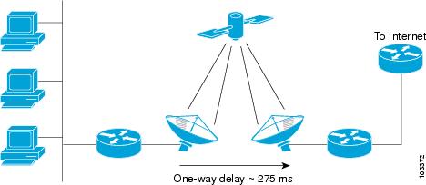
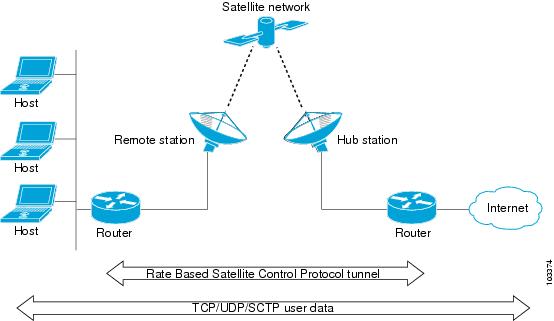
Satellite links have several characteristics that affect the performance of IP protocols over the link. Figure 6 shows that satellite links can have a one-way delay of 275 milliseconds. A round-trip time (RTT) of 550 milliseconds is a very long delay for TCP. Another issue is the high error rates (packet loss rates) that are typical of satellite links as compared to wired links in LANs. Even the weather affects satellite links, causing a decrease in available bandwidth and an increase in RTT and packet loss.
Figure 6 Typical Satellite Link
Long RTT keeps TCP in a slow start mode, which increases the time before the satellite link bandwidth is fully used. TCP and Stream Control Transmission Protocol (SCTP) interpret packet loss events as congestion in the network and start to perform congestion recovery procedures, which reduce the traffic being sent over the link.
Although available satellite link bandwidths are increasing, the long RTT and high error rates experienced by IP protocols over satellite links are producing a high bandwidth-delay product (BDP).
To address the problem of TCP being kept in a slow start mode when a satellite link is used, a disruptive performance enhancing proxy (PEP) solution is often introduced into the network. In Figure 7, you can see that the transport connection is broken up into three sections with hosts on the remote side connecting to the Internet through their default router. The router sends all Internet-bound traffic to the TCP PEP, which terminates the TCP connection to the Internet. The PEP generates a local TCP ACK (TCP spoofing) for all data. Traffic is buffered and retransmitted through a single PEP protocol connection over the satellite link. The second PEP receives the data from the satellite link and retransmits the data over separate TCP connections to the Internet. TCP transmission is disrupted, so dropped packets are not interpreted as TCP congestion and can be retransmitted from buffered data. Minimal TCP ACKs and reduced TCP slow starts allow more bandwidth to be used.
Figure 7 Disruptive TCP PEP Solution
One of the disadvantages to using disruptive TCP PEP is the breaking of the end-to-end model. Some applications cannot work when the flow of traffic is broken, and the PEP has no provision for handling encrypted traffic (IPsec). New transport protocols such as SCTP require special handling or additional code to function with disruptive TCP PEP. An additional managed network component is also required at every satellite router.
RBSCP has been designed to preserve the end-to-end model and provide performance improvements over the satellite link without using a PEP solution. IPsec encryption of clear-text traffic (for example a VPN service configuration) across the satellite link is supported. RBSCP allows two routers to control and monitor the sending rates of the satellite link, thereby increasing the bandwidth utilization. Lost packets are retransmitted over the satellite link by RBSCP, preventing the end host TCP senders from going into slow start mode.
RBSCP is implemented using a tunnel interface as shown in Figure 8. The tunnel can be configured over any network interface supported by Cisco IOS software that can be used by a satellite modem or internal satellite modem network module. IP traffic is sent across the satellite link with appropriate modifications and enhancements that are determined by the router configuration. Standard routing or policy-based routing can be used to determine the traffic to be sent through the RBSCP tunnel.
Figure 8 Nondisruptive RBSCP Solution
RBSCP tunnels can be configured for any of the following features:
•
•
•
•
Path MTU Discovery
Path MTU Discovery (PMTUD) can be enabled on a GRE or IP-in-IP tunnel interface. When PMTUD (RFC 1191) is enabled on a tunnel interface, the router performs PMTUD processing for the GRE (or IP-in-IP) tunnel IP packets. The router always performs PMTUD processing on the original data IP packets that enter the tunnel. When PMTUD is enabled, packet fragmentation is not permitted for packets that traverse the tunnel because the Don't Fragment (DF) bit is set on all the packets. If a packet that enters the tunnel encounters a link with a smaller MTU, the packet is dropped and an ICMP message is sent back to the sender of the packet. This message indicates that fragmentation was required (but not permitted) and provides the MTU of the link that caused the packet to be dropped.
For more detailed information about PMTUD, see the IP Fragmentation and PMTUD document.
NoteUse the tunnel path-mtu-discovery command to enable PMTUD for the tunnel packets, and use the show interfaces tunnel command to verify the tunnel PMTUD parameters. PMTUD currently works only on GRE and IP-in-IP tunnel interfaces.
QoS Options for Tunnels
A tunnel interface supports many of the same quality of service (QoS) features as a physical interface. QoS provides a way to ensure that mission-critical traffic has an acceptable level of performance. QoS options for tunnels include support for applying generic traffic shaping (GTS) directly on the tunnel interface and support for class-based shaping using the modular QoS CLI (MQC). Tunnel interfaces also support class-based policing, but they do not support committed access rate (CAR).
NoteGRE tunnels allow the router to copy the IP precedence bit values of the ToS byte to the tunnel or the GRE IP header that encapsulates the inner packet. Intermediate routers between the tunnel endpoints can use the IP precedence values to classify the packets for QoS features such as policy routing, weighted fair queueing (WFQ), and weighted random early detection (WRED).
When packets are encapsulated by tunnel or encryption headers, QoS features are unable to examine the original packet headers and correctly classify the packets. Packets that travel across the same tunnel have the same tunnel headers, so the packets are treated identically if the physical interface is congested. Tunnel packets can, however, be classified before tunneling and encryption can occur by using the QoS preclassify feature on the tunnel interface or on the crypto map.
NoteFor examples of how to implement some QoS features on a tunnel interface, see the "Example: Configuring QoS Options on Tunnel Interfaces" section.
How to Implement Tunnels
This section contains the following tasks:
•
•
•
•
•
•
•
•
•
•
•
•
•
Determining the Tunnel Type
Before configuring a tunnel, you must determine what type of tunnel you need to create.
SUMMARY STEPS
1.
2.
3.
DETAILED STEPS
Step 1
The passenger protocol is the protocol that you are encapsulating.
Step 2
Table 5 shows how to determine the tunnel CLI command required for the transport protocol that you are using in the tunnel.
Table 5 Determining the Tunnel CLI by the Transport Protocol
CLNS
ctunnel (with optional mode gre keywords)
Other
tunnel mode (with appropriate keyword)
Step 3
Table 6 shows how to determine the appropriate keyword to use with the tunnel mode command. In the tasks that follow in this module, only the relevant keywords for the tunnel mode command are displayed.
What to Do Next
•
•
•
•
–
–
–
–
–
•
Configuring a GRE Tunnel
Perform this task to configure a GRE tunnel. A tunnel interface is used to pass protocol traffic across a network that does not normally support the protocol. To build a tunnel, a tunnel interface must be defined on each of two routers and the tunnel interfaces must reference each other. At each router, the tunnel interface must be configured with a L3 address. The tunnel endpoints, tunnel source, and tunnel destination must be defined, and the type of tunnel must be selected. Optional steps can be performed to customize the tunnel.
Remember to configure the router at each end of the tunnel. If only one side of a tunnel is configured, the tunnel interface may still come up and stay up (unless keepalive is configured), but packets going into the tunnel will be dropped.
In Cisco IOS Release 12.2(8)T and later releases, CEF-switching over multipoint GRE tunnels was introduced. Previously, only process switching was available for multipoint GRE tunnels.
GRE Tunnel Keepalive
Keepalive packets can be configured to be sent over IP-encapsulated GRE tunnels. You can specify the rate at which keepalives will be sent and the number of times that a device will continue to send keepalive packets without a response before the interface becomes inactive. GRE keepalive packets may be sent from both sides of a tunnel or from just one side.
Prerequisites
Ensure that the physical interface to be used as the tunnel source in this task is up and configured with the appropriate IP address. For hardware technical descriptions and information about installing interfaces, see the hardware installation and configuration publication for your product.
Restrictions
GRE tunnel keepalive is not supported in cases where virtual route forwarding (VRF) is applied to a GRE tunnel.
SUMMARY STEPS
1.
2.
3.
4.
5.
6.
7.
8.
9.
10.
11.
12.
13.
DETAILED STEPS
Step 1
enable
Example:Router> enable
Enables privileged EXEC mode.
•
Step 2
configure terminal
Example:Router# configure terminal
Enters global configuration mode.
Step 3
interface type number
Example:Router(config)# interface tunnel 0
Specifies the interface type and number and enters interface configuration mode.
•
•
Step 4
bandwidth kbps
Example:Router(config-if)# bandwidth 1000
Sets the current bandwidth value for an interface and communicates it to higher-level protocols. Specifies the tunnel bandwidth to be used to transmit packets.
•
Note
Step 5
keepalive [period [retries]]
Example:Router(config-if)# keepalive 3 7
(Optional) Specifies the number of times that the device will continue to send keepalive packets without response before bringing the tunnel interface protocol down.
•
•
Note
Step 6
tunnel source {ip-address | interface-type interface-number}
Example:Router(config-if)# tunnel source Ethernet 1
Configures the tunnel source.
•
•
Note
Step 7
tunnel destination {hostname | ip-address}
Example:Router(config-if)# tunnel destination 172.17.2.1
Configures the tunnel destination.
•
•
Note
Step 8
tunnel key key-number
Example:Router(config-if)# tunnel key 1000
(Optional) Enables an ID key for a tunnel interface.
•
•
Note
Step 9
tunnel mode {gre ip | gre multipoint}
Example:Router(config-if)# tunnel mode gre ip
Specifies the encapsulation protocol to be used in the tunnel.
•
•
Step 10
ip mtu bytes
Example:Router(config-if)# ip mtu 1400
(Optional) Set the maximum transmission unit (MTU) size of IP packets sent on an interface.
•
•
Note
Step 11
ip tcp mss mss-value
Example:Router(config-if)# ip tcp mss 250
(Optional) Specifies the maximum segment size (MSS) for TCP connections that originate or terminate on a router.
•
Step 12
tunnel path-mtu-discovery [age-timer {aging-mins | infinite}]
Example:Router(config-if)# tunnel path-mtu-discovery
(Optional) Enables Path MTU Discovery (PMTUD) on a GRE or IP-in-IP tunnel interface.
•
Step 13
end
Example:Router(config-if)# end
Exits interface configuration mode and returns to privileged EXEC mode.
What to Do Next
Proceed to the "Verifying Tunnel Configuration and Operation" section.
Configuring GRE/IPv6 Tunnels
This task explains how to configure a GRE tunnel on an IPv6 network. GRE tunnels can be configured to run over an IPv6 network layer and to transport IPv6 packets in IPv6 tunnels and IPv4 packets in IPv6 tunnels.
Prerequisites
When GRE/IPv6 tunnels are configured, IPv6 addresses are assigned to the tunnel source and the tunnel destination. The tunnel interface can have either IPv4 or IPv6 addresses assigned (this is not shown in the task below). The host or router at each end of a configured tunnel must support both the IPv4 and IPv6 protocol stacks.
SUMMARY STEPS
1.
2.
3.
4.
5.
6.
7.
DETAILED STEPS
Step 1
enable
Example:Router> enable
Enables privileged EXEC mode.
•
Step 2
configure terminal
Example:Router# configure terminal
Enters global configuration mode.
Step 3
interface tunnel tunnel-number
Example:Router(config)# interface tunnel 0
Specifies a tunnel interface and number and enters interface configuration mode.
Step 4
tunnel source {ipv6-address | interface-type interface-number}
Example:Router(config-if)# tunnel source ethernet 0
Specifies the source IPv6 address or the source interface type and number for the tunnel interface.
•
Note
Step 5
tunnel destination ipv6-address
Example:Router(config-if)# tunnel destination 2001:0DB8:0C18:2::300
Specifies the destination IPv6 address for the tunnel interface.
Note
Step 6
tunnel mode gre ipv6
Example:Router(config-if)# tunnel mode gre ipv6
Specifies a GRE IPv6 tunnel.
Note
Step 7
end
Example:Router(config-if)# end
Exits interface configuration mode and returns to privileged EXEC mode.
What to Do Next
Proceed to the "Verifying Tunnel Configuration and Operation" section.
Configuring GRE Tunnel IP Source and Destination VRF Membership
This task explains how to configure the source and destination of a tunnel to belong to any virtual private network (VPN) routing/forwarding (VRFs) tables
Restrictions for GRE Tunnel IP Source and Destination VRF Membership
Cisco 10000 Series Routers
•
•
•
SUMMARY STEPS
1.
2.
3.
4.
5.
6.
7.
8.
DETAILED STEPS
What to Do Next
Proceed to the "Verifying Tunnel Configuration and Operation" section.
Configuring a CTunnel
Perform this task to configure an IP over CLNS tunnel (CTunnel). To configure a CTunnel between a single pair of routers, a tunnel interface must be configured with an IP address, and a tunnel destination must be defined. The destination network service access point (NSAP) address for Router A would be the NSAP address of Router B, and the destination NSAP address for Router B would be the NSAP address of Router A. Ideally, the IP addresses used for the virtual interfaces at either end of the tunnel should be in the same IP subnet. Remember to configure the router at each end of the tunnel.
CTunnel
A CTunnel lets you transport IP traffic over Connectionless Network Service (CLNS), for example, on the data communications channel (DCC) of a SONET ring. CTunnels allow IP packets to be tunneled through the Connectionless Network Protocol (CLNP) to preserve TCP/IP services.
Configuring a CTunnel allows you to telnet to a remote router that has only CLNS connectivity. Other management facilities can also be used, such as Simple Network Management Protocol (SNMP) and TFTP, which otherwise would not be available over a CLNS network.
SUMMARY STEPS
1.
2.
3.
4.
5.
6.
7.
DETAILED STEPS
Troubleshooting Tips
Use the ping command to diagnose basic network connectivity issues.
What to Do Next
Proceed to the "Verifying Tunnel Configuration and Operation" section.
Configuring GRE/CLNS CTunnels to Carry IPv4 and IPv6 Packets
Perform this task to configure a CTunnel in GRE mode to transport IPv4 and IPv6 packets in a CLNS network.
To configure a CTunnel between a single pair of routers, a tunnel interface must be configured with an IP address, and a tunnel destination must be defined. The destination network service access point (NSAP) address for Router A would be the NSAP address of Router B, and the destination NSAP address for Router B would be the NSAP address of Router A. Ideally, the IP addresses used for the virtual interfaces at either end of the tunnel should be in the same IP subnet. Remember to configure the router at each end of the tunnel.
Tunnels for IPv4 and IPv6 Packets over CLNS Networks
Configuring the ctunnel mode gre command on a CTunnel interface enables IPv4 and IPv6 packets to be tunneled over CLNS in accordance with RFC 3147. Compliance with this RFC should allow interoperation between Cisco equipment and that of other vendors in which the same standard is implemented.
RFC 3147 specifies the use of GRE for tunneling packets. The implementation of this feature does not include support for GRE services defined in header fields, such as those used to specify checksums, keys, or sequencing. Any packets received that specify the use of these features will be dropped.
The default CTunnel mode continues to use the standard Cisco encapsulation, which will tunnel only IPv4 packets. If you want to tunnel IPv6 packets, you must use the GRE encapsulation mode. Both ends of the tunnel must be configured with the same mode for either method to work.
Prerequisites
•
•
•
Restrictions
GRE services, such as those used to specify checksums, keys, or sequencing, are not supported. Packets that request use of those features will be dropped.
SUMMARY STEPS
1.
2.
3.
4.
or
ipv6 address ipv6-prefix/prefix-length [eui-64]
5.
6.
7.
8.
DETAILED STEPS
Step 1
enable
Example:Router> enable
Enables privileged EXEC mode.
•
Step 2
configure terminal
Example:Router# configure terminal
Enters global configuration mode.
Step 3
interface ctunnel interface-number
Example:Router(config)# interface ctunnel 102
Creates a virtual interface to transport IP over a CLNS tunnel and enters interface configuration mode.
Note
Step 4
ip address ip-address mask
or
ipv6 address ipv6-prefix/prefix-length [eui-64]
Example:Router(config-if)# ipv6 address 2001:0DB8:1234:5678::3/126
Specifies the IPv4 or IPv6 network assigned to the interface and enables IPv4 or IPv6 packet processing on the interface.
Note
Step 5
ctunnel destination remote-nsap-address
Example:Router(config-if)# ctunnel destination 192.168.30.1
Specifies the destination NSAP address of the CTunnel, where the packets are extracted.
•
Step 6
ctunnel mode gre
Example:Router(config-if)# ctunnel mode gre
Specifies a CTunnel running in GRE mode for both IPv4 and IPv6 traffic.
Note
Step 7
end
Example:Router(config-if)# end
Exits interface configuration mode and returns to privileged EXEC mode.
Step 8
show interfaces ctunnel interface-number
Example:Router# show interfaces ctunnel 102
(Optional) Displays information about an IP over CLNS tunnel.
•
•
What to Do Next
Proceed to the "Verifying Tunnel Configuration and Operation" section.
Configuring Manual IPv6 Tunnels
This task explains how to configure a manual IPv6 overlay tunnel.
Prerequisites
With manually configured IPv6 tunnels, an IPv6 address is configured on a tunnel interface and manually configured IPv4 addresses are assigned to the tunnel source and the tunnel destination. The host or router at each end of a configured tunnel must support both the IPv4 and IPv6 protocol stacks.
SUMMARY STEPS
1.
2.
3.
4.
5.
6.
7.
8.
DETAILED STEPS
Step 1
enable
Example:Router> enable
Enables privileged EXEC mode.
•
Step 2
configure terminal
Example:Router# configure terminal
Enters global configuration mode.
Step 3
interface tunnel tunnel-number
Example:Router(config)# interface tunnel 0
Specifies a tunnel interface and number and enters interface configuration mode.
Step 4
ipv6 address ipv6-prefix/prefix-length [eui-64]
Example:Router(config-if)# ipv6 address 2001:0DB8:1234:5678::3/126
Specifies the IPv6 network assigned to the interface and enables IPv6 processing on the interface.
Note
Step 5
tunnel source {ip-address | interface-type interface-number}
Example:Router(config-if)# tunnel source ethernet 0
Specifies the source IPv4 address or the source interface type and number for the tunnel interface.
•
Step 6
tunnel destination ip-address
Example:Router(config-if)# tunnel destination 192.168.30.1
Specifies the destination IPv4 address for the tunnel interface.
Step 7
tunnel mode ipv6ip
Example:Router(config-if)# tunnel mode ipv6ip
Specifies a manual IPv6 tunnel.
Note
Step 8
end
Example:Router(config-if)# end
Exits interface configuration mode and returns to privileged EXEC mode.
What to Do Next
Proceed to the "Verifying Tunnel Configuration and Operation" section.
Configuring 6to4 Tunnels
This task explains how to configure a 6to4 overlay tunnel.
Prerequisites
With 6to4 tunnels, the tunnel destination is determined by the border-router IPv4 address, which is concatenated to the prefix 2002::/16 in the format 2002:border-router-IPv4-address::/48. The border router at each end of a 6to4 tunnel must support both the IPv4 and IPv6 protocol stacks.
Restrictions
The configuration of only one IPv4-compatible tunnel and one 6to4 IPv6 tunnel is supported on a router. If you choose to configure both of these tunnel types on the same router, we strongly recommend that they not share the same tunnel source.
The reason that a 6to4 tunnel and an IPv4-compatible tunnel cannot share the same interface is that both of them are NBMA "point-to-multipoint" access links and only the tunnel source can be used to reorder the packets from a multiplexed packet stream into a single packet stream for an incoming interface. So when a packet with an IPv4 protocol type of 41 arrives on an interface, that packet is mapped to an IPv6 tunnel interface on the basis of the IPv4 address. However, if both the 6to4 tunnel and the IPv4-compatible tunnel share the same source interface, the router cannot determine the IPv6 tunnel interface to which it should assign the incoming packet.
IPv6 manually configured tunnels can share the same source interface because a manual tunnel is a "point-to-point" link, and both the IPv4 source and IPv4 destination of the tunnel are defined.
SUMMARY STEPS
1.
2.
3.
4.
5.
6.
7.
8.
DETAILED STEPS
Step 1
enable
Example:Router> enable
Enables privileged EXEC mode.
•
Step 2
configure terminal
Example:Router# configure terminal
Enters global configuration mode.
Step 3
interface tunnel tunnel-number
Example:Router(config)# interface tunnel 0
Specifies a tunnel interface and number and enters interface configuration mode.
Step 4
ipv6 address ipv6-prefix/prefix-length [eui-64]
Example:Router(config-if)# ipv6 address 2002:c0a8:6301:1::1/64
Specifies the IPv6 address assigned to the interface and enables IPv6 processing on the interface.
•
Note
Step 5
tunnel source {ip-address | interface-type interface-number}
Example:Router(config-if)# tunnel source ethernet 0
Specifies the source IPv4 address or the source interface type and number for the tunnel interface.
Note
Step 6
tunnel mode ipv6ip 6to4
Example:Router(config-if)# tunnel mode ipv6ip 6to4
Specifies an IPv6 overlay tunnel using a 6to4 address.
Step 7
exit
Example:Router(config-if)# exit
Exits interface configuration mode and returns to global configuration mode.
Step 8
ipv6 route ipv6-prefix/prefix-length tunnel tunnel-number
Example:Router(config)# ipv6 route 2002::/16 tunnel 0
Configures a static route for the IPv6 6to4 prefix 2002::/16 to the specified tunnel interface.
Note
•
What to Do Next
Proceed to the "Verifying Tunnel Configuration and Operation" section.
Configuring IPv4-Compatible IPv6 Tunnels
This task explains how to configure an IPv4-compatible IPv6 overlay tunnel.
Prerequisites
With an IPv4-compatible tunnel, the tunnel destination is automatically determined by the IPv4 address in the low-order 32 bits of IPv4-compatible IPv6 addresses. The host or router at each end of an IPv4-compatible tunnel must support both the IPv4 and IPv6 protocol stacks.
Restrictions
IPv4-compatible tunnels were initially supported for IPv6, but Cisco now recommends that you use a different IPv6 overlay tunneling technique.
SUMMARY STEPS
1.
2.
3.
4.
5.
DETAILED STEPS
What to Do Next
Proceed to the "Verifying Tunnel Configuration and Operation" section.
Configuring ISATAP Tunnels
This task describes how to configure an ISATAP overlay tunnel.
Prerequisites
The tunnel source command used in the configuration of an ISATAP tunnel must point to an interface that is configured with an IPv4 address. The ISATAP IPv6 address and prefix (or prefixes) advertised are configured for a native IPv6 interface. The IPv6 tunnel interface must be configured with a modified EUI-64 address because the last 32 bits in the interface identifier are constructed using the IPv4 tunnel source address.
SUMMARY STEPS
1.
2.
3.
4.
5.
6.
7.
8.
DETAILED STEPS
Step 1
enable
Example:Router> enable
Enables privileged EXEC mode.
•
Step 2
configure terminal
Example:Router# configure terminal
Enters global configuration mode.
Step 3
interface tunnel tunnel-number
Example:Router(config)# interface tunnel 1
Specifies a tunnel interface and number and enters interface configuration mode.
Step 4
ipv6 address ipv6-prefix prefix-length [eui-64]
Example:Router(config-if)# ipv6 address 2001:0DB8:6301::/64 eui-64
Specifies the IPv6 address assigned to the interface and enables IPv6 processing on the interface.
Note
Step 5
no ipv6 nd suppress-ra
Example:Router(config-if)# no ipv6 nd suppress-ra
Enables the sending of IPv6 router advertisements to allow client autoconfiguration.
•
Step 6
tunnel source {ip-address | interface-type interface-number}
Example:Router(config-if)# tunnel source ethernet 1/0/1
Specifies the source IPv4 address or the source interface type and number for the tunnel interface.
Note
Step 7
tunnel mode ipv6ip isatap
Example:Router(config-if)# tunnel mode ipv6ip isatap
Specifies an IPv6 overlay tunnel using an ISATAP address.
Step 8
end
Example:Router(config-if)# end
Exits interface configuration mode and returns to privileged EXEC mode.
What to Do Next
Proceed to the "Verifying Tunnel Configuration and Operation" section.
Configuring the RBSCP Tunnel
Perform this task to configure the RBSCP tunnel. Remember to configure the router at each end of the tunnel.
Prerequisites
Ensure that the physical interface to be used as the tunnel source in this task is already configured.
Restrictions
•
•
•
SUMMARY STEPS
1.
2.
3.
4.
5.
6.
7.
8.
9.
10.
11.
12.
13.
DETAILED STEPS
What to Do Next
This task must be repeated on the router on the other side of the satellite link. Substitute the sample IP addresses, hostnames, and other parameters for the appropriate values on the second router.
After the task is completed on the router on the other side of the satellite link, proceed to the "Verifying RBSCP Tunnel Configuration and Operation" section.
Verifying Tunnel Configuration and Operation
This optional task explains how to verify tunnel configuration and operation. The commands contained in the task steps can be used in any sequence and may need to be repeated. The following commands can be used for GRE tunnels, IPv6 manually configured tunnels, and IPv6 over IPv4 GRE tunnels. This process includes the following general steps (details follow):
Step 1
Step 2
SUMMARY STEPS
1.
2.
3.
4.
5.
DETAILED STEPS
Step 1
Enables privileged EXEC mode. Enter your password if prompted.
Router> enableStep 2
Assuming a generic example suitable for both IPv6 manually configured tunnels and IPv6 over IPv4 GRE tunnels, two routers are configured to be endpoints of a tunnel. Router A has Ethernet interface 0/0 configured as the source for tunnel interface 0 with an IPv4 address of 10.0.0.1 and an IPv6 prefix of 2001:0DB8:1111:2222::1/64. Router B has Ethernet interface 0/0 configured as the source for tunnel interface 1 with an IPv4 address of 10.0.0.2 and an IPv6 prefix of 2001:0DB8:1111:2222::2/64.
To verify that the tunnel source and destination addresses are configured, use the show interfaces tunnel command on Router A.
RouterA# show interfaces tunnel 0Tunnel0 is up, line protocol is upHardware is TunnelMTU 1514 bytes, BW 9 Kbit, DLY 500000 usec,reliability 255/255, txload 1/255, rxload 1/255Encapsulation TUNNEL, loopback not setKeepalive not setTunnel source 10.0.0.1 (Ethernet0/0), destination 10.0.0.2, fastswitch TTL 255Tunnel protocol/transport GRE/IP, key disabled, sequencing disabledTunnel TTL 255Checksumming of packets disabled, fast tunneling enabledLast input 00:00:14, output 00:00:04, output hang neverLast clearing of "show interface" counters neverInput queue: 0/75/0/0 (size/max/drops/flushes); Total output drops: 0Queueing strategy: fifoOutput queue :0/0 (size/max)5 minute input rate 0 bits/sec, 0 packets/sec5 minute output rate 0 bits/sec, 0 packets/sec4 packets input, 352 bytes, 0 no bufferReceived 0 broadcasts, 0 runts, 0 giants, 0 throttles0 input errors, 0 CRC, 0 frame, 0 overrun, 0 ignored, 0 abort8 packets output, 704 bytes, 0 underruns0 output errors, 0 collisions, 0 interface resets0 output buffer failures, 0 output buffers swapped outStep 3
To check that the local endpoint is configured and working, use the ping command on Router A.
RouterA# ping 2001:0DB8:1111:2222::2Type escape sequence to abort.Sending 5, 100-byte ICMP Echos to 2001:0DB8:1111:2222::2, timeout is 2 seconds:!!!!!Success rate is 100 percent (5/5), round-trip min/avg/max = 20/20/20 msStep 4
To check that a route exists to the remote endpoint address, use the show ip route command.
RouterA# show ip route 10.0.0.2Routing entry for 10.0.0.0/24Known via "connected", distance 0, metric 0 (connected, via interface)Routing Descriptor Blocks:* directly connected, via Ethernet0/0Route metric is 0, traffic share count is 1Step 5
To check that the remote endpoint address is reachable, use the ping command on Router A.
NoteRouterA# ping 10.0.0.2Type escape sequence to abort.Sending 5, 100-byte ICMP Echos to 10.0.0.2, timeout is 2 seconds:!!!!!Success rate is 100 percent (5/5), round-trip min/avg/max = 20/21/28 msTo check that the remote IPv6 tunnel endpoint is reachable, use the ping command again on Router A. The same note on filtering also applies to this example.
RouterA# ping 1::2Type escape sequence to abort.Sending 5, 100-byte ICMP Echos to 1::2, timeout is 2 seconds:!!!!!Success rate is 100 percent (5/5), round-trip min/avg/max = 20/20/20 msThese steps may be repeated at the other endpoint of the tunnel.
Verifying RBSCP Tunnel Configuration and Operation
Perform one or both of the following optional tasks to verify the configuration and operation of the RBSCP tunnel configured in the "Configuring the RBSCP Tunnel" section.
•
Verifying That the RBSCP Tunnel Is Active
Perform this task to verify that the RBSCP tunnel is active.
SUMMARY STEPS
1.
2.
DETAILED STEPS
Step 1
Enables privileged EXEC mode. Enter your password if prompted.
Router> enableStep 2
Use this command with the state and tunnel keywords to display information about the current state of the tunnel. In the following sample output the tunnel is shown in an open state.
Router# show rbscp state tunnel 1Tunnel1 is up, line protocol is upRBSCP operational state: OPENRBSCP operating mode: (264h) ack-split window-stuffing inorder SCTP-reportwindow step: 1drop scale: 0ACK split size: 4input drop scale: 2initial TSN: 1hfuzz factor: 0max burst: tunnel 0, network 0next TSN: 1hnext sequence: 16Bhcurrent outstanding: 0max out per RTT: 2062500packets since SACK: 0cumulative ack: 0hTSN at SACK: 0hlast cumulative ack: 0hlast delivered TSN: 0hnext FWDTSN corr: 0hRTO: 704 msRTT: 550 ms srtt_sa: 4391 srtt_sv: 3sentQ: num packets: 0, num bytes: 0tmitQ: num packets: 0, num bytes: 0Use this command with the statistics and tunnel keywords to display statistical information about the tunnel. All counters display totals accumulated since the last clear rbscp command was issued.
Router# show rbscp statistics tunnel 0Tunnel0 is up, line protocol is upRBSCP protocol statistics:Init FWD-TSNs sent 0, received 0TUNNEL-UPs sent 0, received 0CLOSEDs sent 0, received 0TSNs sent 0, resent 0, lost by sender 0TSNs received 0 (duplicates 0)FWD-TSNs sent 144 (heartbeats 0)FWD-TSNs received 0 (ignored 0)FWD-TSNs caused 0 packet drops, 0 whole window dropsSACKs sent 0, received 0 (ignored 0)Recovered with RTX 0Received with delay 0Most released at once 0Failed sends into the: tunnel 1, network 0Dropped due to: excess delay 0, tmit queue full 0Max on any queue: num packets: 0, num bytes: 0Max outstanding: 0
Verifying the RBSCP Traffic
Perform this task to verify that the traffic is being transmitted through the RBSCP tunnel and across the satellite link.
SUMMARY STEPS
1.
2.
DETAILED STEPS
Step 1
Enables privileged EXEC mode. Enter your password if prompted.
Router> enableStep 2
Use this command to show that traffic is being transmitted through the RBSCP tunnel.
Router# show interfaces tunnel 0Tunnel0 is up, line protocol is downHardware is TunnelInternet address is 172.17.1.4/24MTU 1514 bytes, BW 9 Kbit, DLY 500000 usec,reliability 255/255, txload 1/255, rxload 1/255Encapsulation TUNNEL, loopback not setKeepalive not setTunnel source 172.17.1.2, destination 172.20.1.3Tunnel protocol/transport RBSCP/IP, key disabled, sequencing disabledTunnel TTL 255Checksumming of packets disabledTunnel transmit bandwidth 1000 (kbps)Tunnel receive bandwidth 8000 (kbps)RBSCP operational state: invalid (0h)RBSCP operating mode: (2EEh) delay dual-delay drop-long-delay ack-split window-twindow step: 3drop scale : 0ACK split size: 6input drop scale: 5initial TSN: 1hfuzz factor: 0next TSN: 1hnext sequence: 1hcurrent outstanding: 0max out per RTT: 550000packets since SACK: 0cumulative ack: 0hTSN at SACK: 1hlast cumulative ack: 0hlast delivered TSN: 0hnext FWDTSN corr: 0hRTO: 704 msRTT: 550 ms srtt_sa: 0 srtt_sv: 4sentQ: num packets: 0, num bytes: 0tmitQ: num packets: 0, num bytes: 0Last input never, output never, output hang neverLast clearing of "show interface" counters neverInput queue: 0/75/0/0 (size/max/drops/flushes); Total output drops: 0Queueing strategy: fifoOutput queue: 0/0 (size/max)5 minute input rate 0 bits/sec, 0 packets/sec5 minute output rate 0 bits/sec, 0 packets/sec0 packets input, 0 bytes, 0 no bufferReceived 0 broadcasts, 0 runts, 0 giants, 0 throttles0 input errors, 0 CRC, 0 frame, 0 overrun, 0 ignored, 0 abort0 packets output, 0 bytes, 0 underruns0 output errors, 0 collisions, 0 interface resets0 output buffer failures, 0 output buffers swapped out
Configuration Examples for Implementing Tunnels
This section contains the following examples:
•
•
•
•
•
•
•
•
•
•
•
•
•
•
•
Example: Configuring GRE/IPv4 Tunnels
The following example shows a simple configuration of GRE tunneling. Note that Ethernet interface 0/1 is the tunnel source for Router A and the tunnel destination for Router B. Fast Ethernet interface 0/1 is the tunnel source for Router B and the tunnel destination for Router A.
Router A
interface Tunnel0ip address 10.1.1.2 255.255.255.0tunnel source Ethernet0/1tunnel destination 192.168.3.2tunnel mode gre ip!interface Ethernet0/1ip address 192.168.4.2 255.255.255.0Router B
interface Tunnel0ip address 10.1.1.1 255.255.255.0tunnel source FastEthernet0/1tunnel destination 192.168.4.2tunnel mode gre ip!interface FastEthernet0/1ip address 192.168.3.2 255.255.255.0The following example configures a GRE tunnel running both IS-IS and IPv6 traffic between Router A and Router B.
Router A
ipv6 unicast-routingclns routing!interface Tunnel0no ip addressipv6 address 2001:0DB8:1111:2222::1/64ipv6 router isistunnel source Ethernet0/0tunnel destination 10.0.0.2tunnel mode gre ip!interface Ethernet0/0ip address 10.0.0.1 255.255.255.0!router isisnetwork 49.0000.0000.000a.00Router B
ipv6 unicast-routingclns routing!interface Tunnel0no ip addressipv6 address 2001:0DB8:1111:2222::2/64ipv6 router isistunnel source Ethernet0/0tunnel destination 10.0.0.1tunnel mode gre ip!interface Ethernet0/0ip address 10.0.0.2 255.255.255.0!router isisnetwork 49.0000.0000.000b.00address-family ipv6redistribute staticexit-address-familyExample: Configuring GRE/IPv6 Tunnels
The following example shows how to configure a GRE tunnel over an IPv6 transport. Ethernet0/0 has an IPv6 address configured, and this is the source address used by the tunnel interface. The destination IPv6 address of the tunnel is specified directly. In this example, the tunnel carries both IPv4 and IS-IS traffic:
interface Tunnel0ip address 10.1.1.1 255.255.255.0ip router isistunnel source Ethernet0/0tunnel destination 2001:DB8:1111:2222::1tunnel mode gre ipv6!interface Ethernet0/0no ip addressipv6 address 2001:DB8:1111:1111::1/64!router isisnet 49.0001.0000.0000.000a.00Example: Configuring GRE Tunnel IP Source and Destination VRF Membership
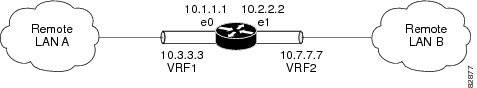
In this example, packets received on interface e0 using VRF green, will be forwarded out of the tunnel through interface e1 using VRF blue. Figure 9 shows a simple tunnel scenario:
Figure 9 GRE Tunnel Diagram
The following example shows the configuration for the tunnel in Figure 9.
ip vrf bluerd 1:1ip vrf greenrd 1:2interface loopback0ip vrf forwarding blueip address 10.7.7.7 255.255.255.255interface tunnel0ip vrf forwarding greenip address 10.3.3.3 255.255.255.0tunnel source loopback 0tunnel destination 10.5.5.5tunnel vrf blueinterface ethernet0ip vrf forwarding greenip address 10.1.1.1 255.255.255.0interface ethernet1ip vrf forwarding blueip address 10.2.2.2 255.255.255.0ip route vrf blue 10.5.5.5 255.255.255.0 ethernet 1Example: Routing Two AppleTalk Networks Across an IP-Only Backbone
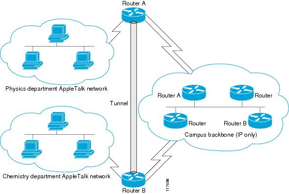
Figure 10 is an example of connecting multiprotocol subnetworks across a single-protocol backbone. The configurations of Router A and Router B follow Figure 10.
Figure 10 Connecting AppleTalk Networks Across an IP-Only Backbone
Router A
interface ethernet 0description physics department AppleTalk LANappletalk cable-range 4001-4001 32!interface fddi 0description connection to campus backboneip address 10.0.8.108 255.255.255.0interface tunnel 0tunnel source fddi 0tunnel destination 10.0.21.20appletalk cable-range 5313-5313 1Router B
interface ethernet 0description chemistry department AppleTalk LANappletalk cable-range 9458-9458 3!interface fddi 0description connection to campus backboneip address 10.0.21.20 255.255.255.0interface tunnel 0tunnel source fddi 0tunnel destination 10.0.8.108appletalk cable-range 5313-5313 2Example: Routing a Private IP Network and a Novell Network Across a Public Service Provider
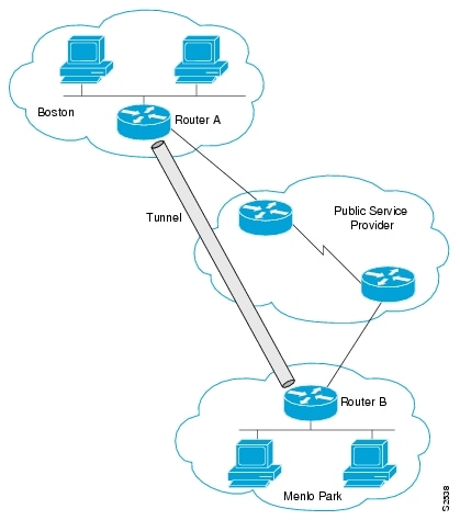
Figure 11 is an example of routing a private IP network and a Novell network across a public service provider. The configurations of Router A and Router B follow Figure 11.
Figure 11 Creating Virtual Private Networks Across WANs
Router A
interface ethernet 0description Boston officeip address 10.1.1.1 255.255.255.0novell network 1e!interface serial 0description connection to public service providerip address 172.17.2.1 255.255.255.0!interface tunnel 0tunnel source serial 0tunnel destination 172.28.5.2ip address 10.1.2.1 255.255.255.0novell network 1fRouter B
interface ethernet 0description Menlo Park officeip address 10.1.3.1 255.255.255.0novell network 31!interface serial 4description connection to public service providerip address 172.28.5.2 255.255.255.0!interface tunnel 0tunnel source serial 4tunnel destination 172.17.2.1ip address 10.1.2.2 255.255.255.0novell network 1fExample: Configuring a CTunnel
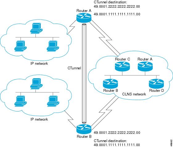
Figure 12 illustrates the creation of a CTunnel between Router A and Router B, as accomplished in the configuration examples that follow.
Figure 12 Creation of a CTunnel
Router A
ip routingclns routinginterface ctunnel 102ip address 10.0.0.1 255.255.255.0ctunnel destination 49.0001.2222.2222.2222.00interface Ethernet0/1clns router isisrouter isisnetwork 49.0001.1111.1111.1111.00router ripnetwork 10.0.0.0Router B
ip routingclns routinginterface ctunnel 201ip address 10.0.0.2 255.255.255.0ctunnel destination 49.0001.1111.1111.1111.00interface Ethernet0/1clns router isisrouter isisnetwork 49.0001.2222.2222.2222.00router ripnetwork 10.0.0.0Example: Configuring GRE/CLNS CTunnels to Carry IPv4 and IPv6 Packets
The following example configures a GRE CTunnel running both IS-IS and IPv6 traffic between Router A and Router B in a CLNS network. The ctunnel mode gre command provides a method of tunneling that is compliant with RFC 3147 and should allow tunneling between Cisco equipment and third-party networking devices.
Router A
ipv6 unicast-routingclns routinginterface ctunnel 102ipv6 address 2001:0DB8:1111:2222::1/64ctunnel destination 49.0001.2222.2222.2222.00ctunnel mode greinterface Ethernet0/1clns router isisrouter isisnetwork 49.0001.1111.1111.1111.00Router B
ipv6 unicast-routingclns routinginterface ctunnel 201ipv6 address 2001:0DB8:1111:2222::2/64ctunnel destination 49.0001.1111.1111.1111.00ctunnel mode greinterface Ethernet0/1clns router isisrouter isisnetwork 49.0001.2222.2222.2222.00To turn off GRE mode and restore the CTunnel to the default Cisco encapsulation routing only between endpoints on Cisco equipment, use either the no ctunnel mode command or the ctunnel mode cisco command. The following example shows the same configuration modified to transport only IPv4 traffic.
Router A
ip routingclns routinginterface ctunnel 102ip address 10.2.2.5 255.255.255.0ctunnel destination 49.0001.2222.2222.2222.00ctunnel mode ciscointerface Ethernet0/1clns router isisrouter isisnetwork 49.0001.1111.1111.1111.00Router B
ip routingclns routinginterface ctunnel 201ip address 10.0.0.5 255.255.255.0ctunnel destination 49.0001.1111.1111.1111.00ctunnel mode ciscointerface Ethernet0/1clns router isisrouter isisnetwork 49.0001.2222.2222.2222.00Example: Configuring Manual IPv6 Tunnels
The following example configures a manual IPv6 tunnel between Router A and Router B. In the example, tunnel interface 0 for both Router A and Router B is manually configured with a global IPv6 address. The tunnel source and destination addresses are also manually configured.
Router A
interface ethernet 0ip address 192.168.99.1 255.255.255.0interface tunnel 0ipv6 address 2001:0db8:c18:1::3/126tunnel source ethernet 0tunnel destination 192.168.30.1tunnel mode ipv6ipRouter B
interface ethernet 0ip address 192.168.30.1 255.255.255.0interface tunnel 0ipv6 address 2001:0db8:c18:1::2/126tunnel source ethernet 0tunnel destination 192.168.99.1tunnel mode ipv6ipExample: Configuring 6to4 Tunnels
The following example configures a 6to4 tunnel on a border router in an isolated IPv6 network. The IPv4 address is 192.168.99.1, which translates to the IPv6 prefix of 2002:c0a8:6301::/48. The IPv6 prefix is subnetted into 2002:c0a8:6301::/64 for the tunnel interface: 2002:c0a8:6301:1::/64 for the first IPv6 network and 2002:c0a8:6301:2::/64 for the second IPv6 network. The static route ensures that any other traffic for the IPv6 prefix 2002::/16 is directed to tunnel interface 0 for automatic tunneling.
interface Ethernet0description IPv4 uplinkip address 192.168.99.1 255.255.255.0!interface Ethernet1description IPv6 local network 1ipv6 address 2002:c0a8:6301:1::1/64!interface Ethernet2description IPv6 local network 2ipv6 address 2002:c0a8:6301:2::1/64!interface Tunnel0description IPv6 uplinkno ip addressipv6 address 2002:c0a8:6301::1/64tunnel source Ethernet0tunnel mode ipv6ip 6to4!ipv6 route 2002::/16 Tunnel0Example: Configuring IPv4-Compatible IPv6 Tunnels
The following example configures an IPv4-compatible IPv6 tunnel that allows BGP to run between a number of routers without having to configure a mesh of manual tunnels. Each router has a single IPv4-compatible tunnel, and multiple BGP sessions can run over each tunnel, one to each neighbor. Ethernet interface 0 is used as the tunnel source. The tunnel destination is automatically determined by the IPv4 address in the low-order 32 bits of an IPv4-compatible IPv6 address. Specifically, the IPv6 prefix 0:0:0:0:0:0 is concatenated to an IPv4 address (in the format 0:0:0:0:0:0:A.B.C.D or ::A.B.C.D) to create the IPv4-compatible IPv6 address. Ethernet interface 0 is configured with a global IPv6 address and an IPv4 address (the interface supports both the IPv6 and IPv4 protocol stacks).
Multiprotocol BGP is used in the example to exchange IPv6 reachability information with the peer 10.67.0.2. The IPv4 address of Ethernet interface 0 is used in the low-order 32 bits of an IPv4-compatible IPv6 address and is also used as the next-hop attribute. Using an IPv4-compatible IPv6 address for the BGP neighbor allows the IPv6 BGP session to be automatically transported over an IPv4-compatible tunnel.
interface tunnel 0tunnel source Ethernet 0tunnel mode ipv6ip auto-tunnelinterface ethernet 0ip address 10.27.0.1 255.255.255.0ipv6 address 3000:2222::1/64router bgp 65000no synchronizationno bgp default ipv4-unicastneighbor ::10.67.0.2 remote-as 65002address-family ipv6neighbor ::10.67.0.2 activateneighbor ::10.67.0.2 next-hop-selfnetwork 2001:2222:d00d:b10b::/64Example: Configuring ISATAP Tunnels
The following example shows the tunnel source defined on Ethernet 0 and the tunnel mode command used to configure the ISATAP tunnel. Router advertisements are enabled to allow client autoconfiguration.
interface Tunnel1tunnel source ethernet 0tunnel mode ipv6ip isatapipv6 address 2001:0DB8::/64 eui-64no ipv6 nd suppress-raExample: Configuring the RBSCP Tunnel
In the following example, Router 1 and Router 2 are configured to send traffic through an RBSCP tunnel over a satellite link.
Router 1
interface Tunnel 0ip unnumbered ethernet1tunnel source ethernet1tunnel destination 172.17.2.1tunnel bandwidth transmit 1000tunnel mode rbscptunnel rbscp ack-split 6tunnel rbscp report!interface ethernet1description Satellite Linkip address 172.20.1.2 255.255.255.0Router 2
interface Tunnel 0ip unnumbered ethernet1tunnel source ethernet1tunnel destination 172.20.1.2tunnel bandwidth transmit 1000tunnel mode rbscptunnel rbscp ack-split 6tunnel rbscp report!interface ethernet1description Satellite Linkip address 172.17.2.1 255.255.255.0Example: Configuring Routing for the RBSCP Tunnel
To control the type of traffic that uses the RBSCP tunnel, you must configure the appropriate routing. If you want to direct all traffic through the tunnel, you can configure a static route.
NoteThe following example shows how to use policy-based routing to route some specific protocol types through the tunnel. In this example, an extended access list allows TCP, Stream Control Transmission Protocol (SCTP), Encapsulating Security Payload (ESP) protocol, and Authentication Header (AH) traffic to travel through the tunnel. All IP traffic is denied.
Router 1 (Local Side)
interface Tunnel1ip unnumbered FastEthernet1/1tunnel source FastEthernet1/1tunnel destination 10.12.0.20tunnel mode rbscptunnel ttl 5tunnel bandwidth transmit 30000tunnel rbscp window-stuff 1tunnel rbscp ack-split 4!interface FastEthernet0/0ip address 10.13.0.1 255.255.255.0ip policy route-map rbscp-pbrduplex autospeed auto!interface FastEthernet1/1description Satellite Linkip address 10.12.0.1 255.255.255.0duplex autospeed auto!ip route 10.15.0.0 255.255.255.0 FastEthernet1/1!ip access-list extended rbscp-aclpermit tcp any 10.15.0.0 0.0.0.255permit 132 any 10.15.0.0 0.0.0.255permit esp any 10.15.0.0 0.0.0.255permit ahp any 10.15.0.0 0.0.0.255deny ip any any!route-map rbscp-pbr permit 10match ip address rbscp-aclset interface Tunnel1Router 2 (Remote Side)
ip dhcp pool CLIENTimport allnetwork 10.15.0.0 255.255.255.0default-router 10.15.0.1domain-name engineer.chicago.il.usdns-server 10.10.0.252!interface Tunnel1ip unnumbered FastEthernet0/1tunnel source FastEthernet0/1tunnel destination 10.12.0.1tunnel mode rbscptunnel ttl 5tunnel bandwidth transmit 30000tunnel rbscp window-stuff 1tunnel rbscp ack-split 4!interface FastEthernet0/0description Local LANip address 10.15.0.1 255.255.255.0ip policy route-map rbscp-pbrduplex autospeed auto!interface FastEthernet0/1description Satellite Linkip address 10.12.0.20 255.255.255.0duplex autospeed auto!ip route 0.0.0.0 0.0.0.0 FastEthernet0/1!ip access-list extended rbscp-aclpermit tcp any anypermit 132 any anypermit esp any anypermit ahp any anydeny ip any any!route-map rbscp-pbr permit 10match ip address rbscp-aclset interface Tunnel1Example: Configuring QoS Options on Tunnel Interfaces
The following sample configuration applies generic traffic shaping (GTS) directly on the tunnel interface. In this example the configuration shapes the tunnel interface to an overall output rate of 500 kbps. For more details on GTS, see the "Regulating Packet Flow Using Traffic Shaping" chapter of the Cisco IOS Quality of Service Solutions Configuration Guide.
interface Tunnel0ip address 10.1.2.1 255.255.255.0traffic-shape rate 500000 125000 125000 1000tunnel source 10.1.1.1tunnel destination 10.2.2.2The following sample configuration shows how to apply the same shaping policy to the tunnel interface with the Modular QoS CLI (MQC) commands. For more details on MQC, see the "Modular Quality of Service Command-Line Interface" chapter of the Cisco IOS Quality of Service Solutions Configuration Guide.
policy-map tunnelclass class-defaultshape average 500000 125000 125000!interface Tunnel0ip address 10.1.2.1 255.255.255.0service-policy output tunneltunnel source 10.1.35.1tunnel destination 10.1.35.2Policing Example
When an interface becomes congested and packets start to queue, you can apply a queueing method to packets that are waiting to be transmitted. Cisco IOS logical interfaces—tunnel interfaces in this example—do not inherently support a state of congestion and do not support the direct application of a service policy that applies a queueing method. Instead, you need to apply a hierarchical policy. Create a "child" or lower-level policy that configures a queueing mechanism, such as low latency queueing with the priority command and class-based weighted fair queueing (CBWFQ) with the bandwidth command.
policy-map childclass voicepriority 512Create a "parent" or top-level policy that applies class-based shaping. Apply the child policy as a command under the parent policy because admission control for the child class is done according to the shaping rate for the parent class.
policy-map tunnelclass class-defaultshape average 2000000service-policy childApply the parent policy to the tunnel interface.
interface tunnel0service-policy tunnelIn the following example, a tunnel interface is configured with a service policy that applies queueing without shaping. A log message is displayed noting that this configuration is not supported.
interface tunnel1service-policy output childClass Based Weighted Fair Queueing not supported on this interfaceFor more details on QoS traffic policing, see the Cisco IOS Quality of Service Solutions Configuration Guide.
Example: Configuring EoMPLS over GRE
The following sample provides the EoMPLS over GRE configuration sequence:
PE1 Configuration
vrf definition VPN1rd 100:1address-family ipv4route-target both 100:1exit-address-family!mpls label protocol ldpmpls ldp neighbor 10.10.10.11 targetedmpls ldp router-id Loopback0 force!interface Tunnel0ip address 100.1.1.11 255.255.255.0mpls label protocol ldpmpls ipkeepalive 10 3tunnel source TenGigabitEthernet2/1/0tunnel destination 50.1.3.2!interface Loopback0ip address 10.10.10.10 255.255.255.255!interface TenGigabitEthernet2/1/0mtu 9216ip address 10.1.1.1 255.255.255.0!interface TenGigabitEthernet9/1no ip address!interface TenGigabitEthernet9/1.11vrf forwarding VPN1encapsulation dot1Q 300ip address 192.168.1.1 255.255.255.0!interface TenGigabitEthernet9/2mtu 9216no ip addressxconnect 10.10.10.11 200 encapsulation mpls!router bgp 65000bgp log-neighbor-changesneighbor 10.10.10.11 remote-as 65000neighbor 10.10.10.11 update-source Loopback0neighbor 192.168.1.2 remote-as 100!address-family vpnv4neighbor 10.10.10.11 activateneighbor 10.10.10.11 send-community extended!address-family ipv4 vrf VPN1no synchronizationneighbor 192.168.1.2 remote-as 100neighbor 192.168.1.2 activateneighbor 192.168.1.2 send-community extended!ip route 10.10.10.11 255.255.255.255 Tunnel0ip route 10.1.3.0 255.255.255.0 10.1.1.2PE2 Configurationvrf definition VPN1rd 100:1address-family ipv4route-target both 100:1exit-address-family!mpls ldp neighbor 10.10.10.10 targetedmpls label protocol ldpmpls ldp router-id Loopback0 force!interface Tunnel0ip address 100.1.1.10 255.255.255.0mpls label protocol ldpmpls ipkeepalive 10 3tunnel source TenGigabitEthernet3/3/0tunnel destination 10.1.1.1!interface Loopback0ip address 10.10.10.11 255.255.255.255!interface TenGigabitEthernet2/1mtu 9216no ip addressxconnect 10.10.10.10 200 encapsulation mpls!interface TenGigabitEthernet2/3mtu 9216no ip address!interface TenGigabitEthernet2/3.11vrf forwarding VPN1encapsulation dot1Q 300ip address 192.168.2.1 255.255.255.0!interface TenGigabitEthernet3/3/0mtu 9216ip address 10.1.3.2 255.255.255.0!router bgp 65000bgp log-neighbor-changesneighbor 10.10.10.10 remote-as 65000neighbor 10.10.10.10 update-source Loopback0neighbor 192.168.2.2 remote-as 200!address-family vpnv4neighbor 10.10.10.10 activateneighbor 10.10.10.10 send-community extendedexit-address-family!address-family ipv4 vrf VPN1no synchronizationneighbor 192.168.2.2 remote-as 200neighbor 192.168.2.2 activateneighbor 192.168.2.2 send-community extendedexit-address-family¡ip route 10.10.10.10 255.255.255.255 Tunnel0ip route 10.1.1.0 255.255.255.0 10.1.3.1Where to Go Next
If you have implemented IPv6 tunnels, you may want to proceed to one of the following modules:
•
/48 6to4 prefix that you have created from your IPv4 address.•
•
Additional References
Related Documents
Cisco IOS commands
Tunnel commands: complete command syntax, command mode, defaults, command history, usage guidelines, and examples
Cisco IOS Interface and Hardware Component Command Reference
CLNS commands: complete command syntax, command mode, defaults, command history, usage guidelines, and examples
IP commands: complete command syntax, command mode, defaults, command history, usage guidelines, and examples
•
•
IPv6 commands: complete command syntax, command mode, defaults, command history, usage guidelines, and examples
IPv6 Features
Regulating Packet Flow on a Per-Interface Basis - Using Generic Traffic Shaping
Modular QoS CLI configuration
Virtual interface configuration
Cisco IOS Interface and Hardware Component Configuration Guide
Configuration example for GRE over IP Security (IPSec) where the GRE/IPSec tunnel is going through a firewall doing Network Address Translation (NAT)
Configuring Multiprotocol Label Switching
Standards
No new or modified standards are supported, and support for existing standards has not been modified.
—
MIBs
RFCs
Technical Assistance
Feature Information for Implementing Tunnels
Table 7 lists the features in this module and provides links to specific configuration information.
Use Cisco Feature Navigator to find information about platform support and software image support. Cisco Feature Navigator enables you to determine which software images support a specific software release, feature set, or platform. To access Cisco Feature Navigator, go to http://www.cisco.com/go/cfn. An account on Cisco.com is not required.
Note
Table 7 Feature Information for Implementing Tunnels
CEF-Switched Multipoint GRE Tunnels
12.2(8)T
15.0(1)MThe CEF-Switched Multipoint GRE Tunnels feature enables CEF switching of IP traffic to and from multipoint GRE tunnels. Tunnel traffic can be forwarded to a prefix through a tunnel destination when both the prefix and the tunnel destination are specified by the application.
This feature introduces CEF switching over multipoint GRE tunnels. Previously, only process switching was available for multipoint GRE tunnels.
The following sections provide information about this feature:
No commands were introduced or modified by this feature.
CLNS Support for GRE Tunneling of IPv4 and IPv6 Packets in CLNS Networks
12.3(7)T
12.2(25)S12.2(33)SRA
Support of the GRE tunnel mode allows Cisco CTunnels to transport IPv4 and IPv6 packets over CLNS-only networks in a manner that allows interoperation between Cisco networking equipment and that of other vendors. This feature provides compliance with RFC 3147.
The following sections provide information about this feature:
•
•
•
The following command was introduced by this feature: ctunnel mode.
GRE Tunnel IP Source and Destination VRF Membership
12.0(23)S
12.2(20)S
12.2(27)SBC
12.3(2)T12.2(33)SRA
12.2(33)SRB
12.2(31)SB5
12.4(15)TAllows you to configure the source and destination of a tunnel to belong to any VPN VRF table.
In 12.0(23)S, this feature was introduced.
In 12.2(20)S this feature became available on Cisco 7304 router using the NSE-100 in the PXF processing path.
In 12.2(31)SB5, support was added for the Cisco 10000 series router for the PRE2 and PRE3.
The following sections provide information about this feature:
•
•
•
The following command was introduced to support this feature: tunnel vrf.
GRE Tunnel Keepalive
12.2(8)T
12.0(23)S
15.0(1)M
Cisco IOS XE 3.1.0SGThe GRE Tunnel Keepalive feature provides the capability of configuring keepalive packets to be sent over IP-encapsulated generic routing encapsulation (GRE) tunnels. You can specify the rate at which keepalives will be sent and the number of times that a device will continue to send keepalive packets without a response before the interface becomes inactive. GRE keepalive packets may be sent from both sides of a tunnel or from just one side.
The following section provides information about this feature:
The following command was introduced by this feature: keepalive (tunnel interfaces).
Rate-Based Satellite Control Protocol
12.3(7)T
Rate-Based Satellite Control Protocol (RBSCP) was designed for wireless or long-distance delay links with high error rates, such as satellite links. Using tunnels, RBSCP can improve the performance of certain IP protocols, such as TCP and IP Security (IPSec), over satellite links without breaking the end-to-end model.
The following sections provide information about this feature:
•
•
The following commands were introduced or modified by this feature: clear rbscp, debug tunnel rbscp, show rbscp, tunnel bandwidth, tunnel mode, tunnel rbscp ack-split, tunnel rbscp delay, tunnel rbscp input-drop, tunnel rbscp long-drop, tunnel rbscp report, tunnel rbscp window-stuff.
Tunnel ToS
12.0(17)S
12.0(17)ST
12.2(8)T
12.2(14)S
15.0(1)MThe Tunnel ToS feature allows you to configure the ToS and Time-to-Live (TTL) byte values in the encapsulating IP header of tunnel packets for an IP tunnel interface on a router. The Tunnel ToS feature is supported on Cisco Express Forwarding (CEF), fast switching, and process switching forwarding modes.
The following section provides information about this feature:
The following commands were introduced or modified by this feature: show interfaces tunnel, tunnel tos, tunnel ttl.
Cisco and the Cisco Logo are trademarks of Cisco Systems, Inc. and/or its affiliates in the U.S. and other countries. A listing of Cisco's trademarks can be found at www.cisco.com/go/trademarks. Third party trademarks mentioned are the property of their respective owners. The use of the word partner does not imply a partnership relationship between Cisco and any other company. (1005R)
Any Internet Protocol (IP) addresses used in this document are not intended to be actual addresses. Any examples, command display output, and figures included in the document are shown for illustrative purposes only. Any use of actual IP addresses in illustrative content is unintentional and coincidental
© 2007—2011 Cisco Systems, Inc. All rights reserved.