配置Catalyst 3750 QoS
下载选项
非歧视性语言
此产品的文档集力求使用非歧视性语言。在本文档集中,非歧视性语言是指不隐含针对年龄、残障、性别、种族身份、族群身份、性取向、社会经济地位和交叉性的歧视的语言。由于产品软件的用户界面中使用的硬编码语言、基于 RFP 文档使用的语言或引用的第三方产品使用的语言,文档中可能无法确保完全使用非歧视性语言。 深入了解思科如何使用包容性语言。
关于此翻译
思科采用人工翻译与机器翻译相结合的方式将此文档翻译成不同语言,希望全球的用户都能通过各自的语言得到支持性的内容。 请注意:即使是最好的机器翻译,其准确度也不及专业翻译人员的水平。 Cisco Systems, Inc. 对于翻译的准确性不承担任何责任,并建议您总是参考英文原始文档(已提供链接)。
简介
本文档介绍Catalyst 3750交换机QoS功能,例如分类、标记、管制、队列和调度。
先决条件
要求
Cisco 建议您了解以下主题:
使用的组件
本文档中的信息基于以下软件和硬件版本:
-
Cisco Catalyst 3750 交换机
-
Cisco IOS® 软件版本 12.2(35)SE2
本文档中的信息都是基于特定实验室环境中的设备编写的。本文档中使用的所有设备最初均采用原始(默认)配置。如果您的网络处于活动状态,请确保您了解所有命令的潜在影响。
规则
有关文档规则的详细信息,请参阅 Cisco 技术提示规则。
QoS 概述
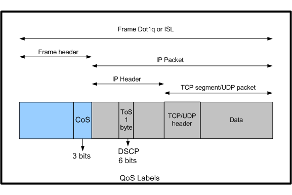
使用 QoS,您可以优先处理特定类型的数据流,而牺牲对其他数据流的处理。您可以使用QoS标签区分流量。
第 3 层 IP 报头中最常用的两个 QoS 标签是 IP 优先级字段和 DSCP 字段。
第2层帧头中的QoS标签称为服务类别(CoS)。 Catalyst 交换机 QoS 工具可基于第 3 层 QoS 标签或第 2 层 QoS 标签提供优先处理。
本文档提供的各种示例可帮助您了解在 Cisco Catalyst 交换机中第 2 层和第 3 层 QoS 标签的用法。
 Cisco Catalyst交换机中的第2层和第3层QoS标签使用
未启用 QoS 的 Cisco Catalyst 3750 交换机
默认情况下,QoS 在 Catalyst 3750 交换机上处于禁用状态。当 QoS 处于禁用状态时,所有帧/数据包均直接通过交换机,不做任何更改。
例如,如果进入交换机的帧的 CoS 为 5,帧中的数据包的 DSCP 为 EF,则 CoS 和 DSCP 标签不会更改。
数据流在离开时具有与进入时相同的 CoS 和 DSCP 值。所有数据流(包括语音)均“尽最大努力按原样”提供。
Switch#show mls qos
QoS is disabled
QoS ip packet dscp rewrite is enabled

!--- Even though it says QoS ip packet dscp rewrite is enabled,
!--- the switch does not alter the DSCP label on the packets when
!--- the QoS is disabled.
Cisco Catalyst 3750 交换机 QoS 功能
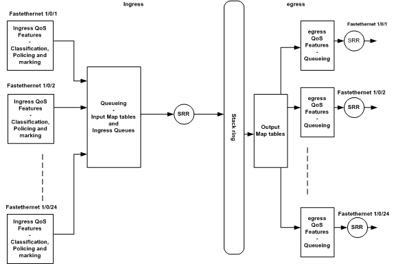
在 3750 交换机上启用 QoS 后,默认情况下会启用一些入口和出口 QoS 功能。下图显示了交换机的 QoS 体系结构的高级视图:
 交换机QoS架构高级视图
以下是基于该图的要点汇总:
-
入口 QoS 功能(例如分类、标记和策略)可以按端口逐个进行配置。
-
输入映射表和入口队列可以进行全局配置。这些不能按端口逐个进行配置。
-
入口队列的 SRR 可以进行全局配置。
-
堆栈环带宽取决于堆栈布线。如果以全部带宽连接堆栈,则可获得 32Gbps 带宽。此带宽由堆栈中的所有交换机共享。
-
输出映射表和出口队列可以进行全局配置。可以设置二个队列集配置,并可以为端口应用任何一个队列集配置。
-
出口队列的 SRR 可以按端口逐个进行配置。
入口 QoS 功能
本部分介绍各种可能的入口 QoS 配置的概念。本节包括以下主题:
默认入口 QoS 配置
以下是交换机在启用 QoS 后默认的帧处理方式:
-
一个帧进入交换机端口,且未对该帧进行标记(这表示该端口为接入端口,并且该帧在进入交换机时未进行 ISL 或 dot1q 封装)。
-
交换机使用 dot1q 封装该帧(忽略 ISL,因为 dot1q 是所有新交换机上的默认选项)。
-
在 dot1q 帧标记中,存在名为 802.1p 优先级位的三个可用位,也称为 CoS。这些位均设置为 0。
-
随后,交换机基于 CoS-DSCP 映射表计算 DSCP 值。根据表,交换机将DSCP值设置为0。DSCP值位于数据包的IP报头。
总之,如果 QoS 在交换机上处于启用状态,默认情况下,进入交换机的帧的 CoS 和 DSCP 值将设置为 0。
分类和标记
与路由器不同,在 Cisco Catalyst 交换机中,QoS 分类和标记操作不尽相同。
在思科路由器中,可以使用MQC根据传入数据包DSCP值或访问控制列表(ACL)对数据包进行分类。
这取决于您是否信任传入的数据包的 QoS 标签。在 Cisco Catalyst 3750 交换机中,可以基于传入的 CoS/DSCP 值进行分类,也可以基于 ACL 对帧进行分类。
基于传入的 CoS/DSCP 值的配置可以通过三种不同方式实现:
-
使用基于mls qos接口的命令进行基于端口的配置
-
基于MQC的配置,包括类映射和策略映射
-
基于 VLAN 进行配置
您可以使用这三种方法中的任意一种。不能在一个端口中使用多种方法。例如,您已在端口上配置了mls qos trust命令。
在使用 service-policy input <policy-map-name> 命令配置该端口时,会自动删除 mls qos trust cos 命令。
分类和标记 — 基于端口部分介绍了基于端口的配置。
“分类和标记 — MQC基础”部分解释了基于MQC的分类。
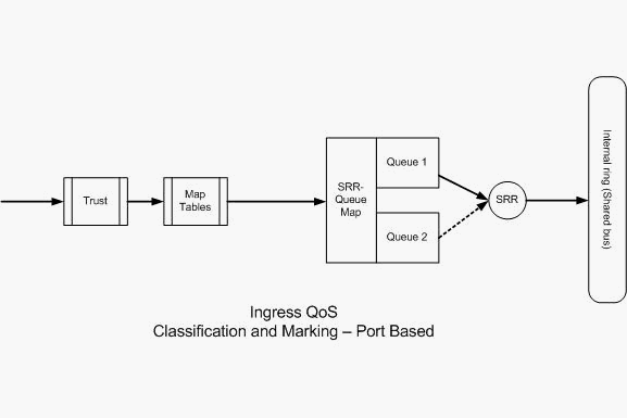
分类和标记 - 基于端口
本部分将介绍基于特定于接口的配置的分类。在标题为“分类和标记”的部分可能会遇到问题。
这是因为,在Cisco Catalyst 3750交换机中,帧(帧内的数据包)的CoS或DSCP值用映射表重新标记。但映射表在 Cisco 路由器中不可用。
它们仅在 Cisco Catalyst 交换机中可用。您可以在本节中看到这些表的功能。
本部分将讨论以下两种配置:
 分类和标记 — 基于端口
分类 - 端口信任配置
传入的数据包或帧可能已经分配了 QoS 标签。可能会遇到以下问题:
-
是否信任端口上传入的数据包/帧的 QoS 标签?
-
如果 IP 电话和 PC 连接到端口,是否信任该电话、PC 或二者的 QoS 标签?
如果不信任传入的数据包/帧的 QoS 标签,则需要基于访问列表对数据包进行分类并标记 QoS 标签。
如果信任传入的数据包/帧的 QoS 标签,则另一个问题是,是否需要信任端口上传入的数据包/帧的 CoS 值或 DSCP 值?
这取决于所采用的方案。在本部分中,您可以看到各种不同的方案及其示例。
端口信任配置选项为:
Switch(config-if)#mls qos trust ?
  cos            cos keyword
  device         trusted device class
  dscp           dscp keyword
  ip-precedence  ip-precedence keyword
  <cr>
-
示例1:如果端口是接入端口或第3层端口,则需要配置mls qos trust dscp命令。
您无法使用mls qos trust cos命令,因为来自接入端口或第3层端口的帧不包含dot1q或ISL标记。CoS 位仅存在于 dot1q 或 ISL 帧中。
interface GigabitEthernet1/0/1
 description **** Layer 3 Port ****
 no switchport
 ip address 192.168.10.1 255.255.255.0
 mls qos trust dscp
end
interface GigabitEthernet1/0/2
 description **** Access Port ****
 switchport access vlan 10
 switchport mode access
 mls qos trust dscp
end
-
示例2:如果端口是中继端口,则可以配置mls qos trust cos 或mls qos trust dscp命令。
如果端口配置为信任 DSCP,则将使用 dscp-cos 映射表计算 CoS 值。同样,如果端口配置为信任 CoS,则将使用 cos-dscp 映射表计算 DSCP 值。
interface GigabitEthernet1/0/3
description **** Trunk Port ****
switchport trunk encapsulation dot1q
switchport mode trunk
switchport trunk native vlan 5
switchport trunk allowed vlan 5,10,20,30,40,50
mls qos trust cos
end
interface GigabitEthernet1/0/12
 description **** Cisco IP Phone  ****
 switchport access vlan 10
 switchport mode access
 switchport voice vlan 20
 mls qos trust cos
 spanning-tree portfast
end

!--- The Cisco IP Phone uses IEEE 802.1Q frames for Voice
!--- VLAN traffic.
-
示例3:如果端口是dot1q中继端口,并且使用mls qos trust cos命令配置该端口,则本地VLAN帧的CoS和DSCP值可以为0。由于本地VLAN帧未标记,并且帧在进入交换机后被标记,因此交换机可以将默认CoS值设置为0,并且CoS到DSCP表将DSCP值设置为0。

注意:来自本地VLAN的数据包的DSCP值重置为0。
您还可以使用mls qos cos <0-7>命令配置交换机端口,以将无标记帧的默认CoS值从0更改为0到7之间的任何其他值。
此命令不会更改已标记的帧的 CoS 值。
例如,使用接入 VLAN 10 和语音 VLAN 20 配置端口 GigabitEthernet1/0/12。
interface GigabitEthernet1/0/12
 description **** Cisco IP Phone  ****
 switchport access vlan 10
 switchport mode access
 switchport voice vlan 20
 mls qos trust cos
 spanning-tree portfast

!--- The Cisco IP Phone uses IEEE 802.1Q frames for Voice
!--- VLAN traffic. Voice VLAN is only supported on access ports and not
!--- on trunk ports, even though the configuration is allowed.

end
默认情况下,PC 将发送未标记的数据。无论电话上的接入端口的信任状态如何,来自连接到 Cisco IP 电话的设备的未标记数据流都将直接通过电话,不做任何更改。
电话发送带语音VLAN ID 20的dot1q标记帧。因此,如果使用mls qos trust cos命令配置端口,它将信任来自电话的帧的CoS值(标记帧),并将来自PC的帧(未标记)的CoS值设置为0。
随后,由于在 CoS-DSCP 映射表中,与 CoS 值 0 对应的 DSCP 值为 0,因此 CoS-DSCP 映射表会将帧中所含数据包的 DSCP 值设置为 0。
如果来自PC的数据包有任何特定的DSCP值,则该值可以重置为0。如果在端口上配置mls qos cos 3命令,则会将来自PC的所有帧的CoS值设置为3,并且不会改变来自电话的帧的CoS值。
interface GigabitEthernet1/0/12
 description **** Cisco IP Phone  ****
 switchport access vlan 10
 switchport mode access
 switchport voice vlan 20
 mls qos trust cos
 mls qos cos 3
 spanning-tree portfast
end
如果使用mls qos cos 3 override命令配置端口,则会将所有帧(已标记和未标记)的CoS值设置为3。它会覆盖以前配置的信任值。
interface GigabitEthernet1/0/12
 description **** Cisco IP Phone  ****
 switchport access vlan 10
 switchport mode access
 switchport voice vlan 20
 mls qos trust cos
 mls qos cos 3 override

!--- Overrides the mls qos trust cos.


!--- Applies CoS value 3 on all the incoming packets on both
!--- the vlan 10 and 20.

 spanning-tree portfast
end
-
示例4:例如,查看端口gi 1/0/12配置:
interface GigabitEthernet1/0/12
 description **** Cisco IP Phone  ****
 switchport access vlan 10
 switchport mode access
 switchport voice vlan 20
 mls qos trust cos
 spanning-tree portfast
end
如果PC使用VLAN 20标记其帧,它还会将CoS值设置为5。交换机处理来自连接到Cisco IP电话接入端口的设备的数据标记流量(IEEE 802.1Q或IEEE 802.1p帧类型的流量)。
由于接口配置为信任 CoS 值,因此通过 Cisco IP 电话上的接入端口接收的所有数据流都将直接通过电话,不做任何更改。
交换机也信任并允许来自 PC 的数据流,并给予与 IP 电话数据流相同的优先级。
这不是您希望看到的结果。使用switchport priority extend cos<cos-value>命令可避免这种情况。
interface GigabitEthernet1/0/12
 description **** Cisco IP Phone  ****
 switchport access vlan 10
 switchport mode access
 switchport voice vlan 20
 mls qos trust cos
 switchport priority extend cos 0

!--- Overrides the CoS value of PC traffic to 0.

 spanning-tree portfast
end
switchport priority extend cos <cos-value> 命令会对电话进行配置,以便 IP 电话将 PC 数据流的 CoS 值更改为 0。
-
示例5:例如,在同一接口中,有人将PC直接连接到交换机,并使用dot1q帧标记具有较高CoS值的PC数据。可以使用mls qos trust device cisco-phone命令避免这种情况。
interface GigabitEthernet1/0/12
 description **** Cisco IP Phone  ****
 switchport access vlan 10
 switchport mode access
 switchport voice vlan 20
 mls qos trust cos
 switchport priority extend cos 0
 mls qos trust device cisco-phone

!--- Specify that the Cisco IP Phone is a trusted device.

 spanning-tree portfast
end
-
示例6:例如,在接口GigabitEthernet1/0/12中,您必须信任来自PC的QoS标签。
此外,PC 连接到本地 VLAN 10。在这种情况下,由于 PC 数据包未标记 CoS 值,因此 mls qos trust cos 命令没有任何作用。它仅标记DSCP值。
因此,交换机添加dot1q帧并将默认CoS值配置为0。然后,CoS-DSCP表计算并将DSCP值重置为0。
要解决此问题,有二种选择。一种选择是使用MQC配置分类和标记。
可以创建 ACL,根据源、目标 IP 地址以及源/目标端口号来匹配 PC 数据流。然后,可以在类映射中匹配此 ACL。
可以创建策略映射以信任此数据流。将在下一部分中讨论此解决方案。本部分讨论第二种方法。第二种方法是,信任 DSCP 标签而不是 CoS 标签。
然后,DSCP-CoS 标签将计算并设置与 DSCP 值对应的 CoS 值。
interface GigabitEthernet1/0/12
 description **** Cisco IP Phone  ****
 switchport access vlan 10
 switchport mode access
 switchport voice vlan 20
 mls qos trust dscp
 spanning-tree portfast
end
第一种方法是首选方法,因为不建议信任所有PC流量QoS标签。
标记 - QoS 映射表配置
在启用 QoS 后,将使用默认值创建映射表并启用映射表。
Distribution1#show mls qos maps cos-dscp
   Cos-dscp map:
        cos:   0  1  2  3  4  5  6  7
     --------------------------------
       dscp:   0  8 16 24 32 40 48 56

Distribution1#show mls qos maps dscp-cos
   Dscp-cos map:
     d1 :  d2 0  1  2  3  4  5  6  7  8  9
     ---------------------------------------
      0 :    00 00 00 00 00 00 00 00 01 01
      1 :    01 01 01 01 01 01 02 02 02 02
      2 :    02 02 02 02 03 03 03 03 03 03
      3 :    03 03 04 04 04 04 04 04 04 04
      4 :    05 05 05 05 05 05 05 05 06 06
      5 :    06 06 06 06 06 06 07 07 07 07
      6 :    07 07 07 07
-
示例1:如果端口配置为信任CoS,则所有传入的CoS值都是受信任的,并且会根据CoS-DSCP表重新标记DSCP值。根据默认的 CoS-DSCP 配置,这些值将按以下方式映射:
CoS DSCP(十进制) DSCP 0 0 默认 1 8 CS1 2 16 CS2 3 24 CS3 4 32 CS4 5 40 CS5 6 48 CS6 7 56 CS7 此处需要注意的一个重要值是DSCP值对应于CoS值5。它是CS5。示例2介绍了此值。
-
示例2:例如,接口GigabitEthernet1/0/12配置为信任CoS。
interface GigabitEthernet1/0/12
 description **** Cisco IP Phone  ****
 switchport access vlan 10
 switchport mode access
 switchport voice vlan 20
 mls qos trust cos
 spanning-tree portfast
end
当 Cisco IP 电话将数据流发送到交换机时,它会使用 CoS 5 和 DSCP EF 标记语音有效负载。当数据流进入端口 Gi 1/0/12 时,交换机将信任 CoS 值。然后,交换机从 CoS-DSCP 表获得与 CoS 值 5 对应的 DSCP 值 CS5 (40)。CoS 5的所有语音有效负载都标有DSCP值CS5。这不是期望值。语音有效负载所需的 DSCP 值为 DSCP EF。默认情况下,其他 CoS 值均可根据 RFC 正确映射到 DSCP 值。
-
以下配置可帮助您配置 CoS-DSCP 映射表,以更改与 CoS 5 对应的 DSCP 值 EF。
Distribution1(config)#mls qos map cos-dscp 0  8 16 24 32 46 48 56

!--- DSCP 46 is EF
进行此配置后,这些值将按以下方式映射:
CoS DSCP(十进制) DSCP 0 0 默认 1 8 CS1 2 16 CS2 3 24 CS3 4 32 CS4 5 46 EF 6 48 CS6 7 56 CS7 -
示例3:如果端口配置为信任DSCP,则所有传入的DSCP值都是受信任的,并且会根据DSCP-CoS表重新标记CoS值。根据默认的 DSCP-CoS 配置,这些值将按以下方式映射:
DSCP DSCP(十进制) CoS 默认 0-7 0 CS1 AF11 AF12 AF13 8-15 1 CS2 AF21 AF22 AF23 16-23 2 CS3 AF31 AF32 AF33 24-31 3 CS4 AF41 AF42 AF43 32-39 4 CS5 EF 40-47 5 CS6 48-55 6 CS7 56-63 7
您不需要更改这些默认值。
下表汇总了 DSCP 值和 CoS 值,仅供参考:
| DSCP(十进制) | DSCP | CoS |
|---|---|---|
| 0 | 默认 | 0 |
| 8 | CS1 | 1 |
| 10 | AF11 | 1 |
| 12 | AF12 | 1 |
| 14 | AF13 | 1 |
| 16 | CS2 | 2 |
| 18 | AF21 | 2 |
| 20 | AF22 | 2 |
| 22 | AF23 | 2 |
| 24 | CS3 | 3 |
| 26 | AF31 | 3 |
| 28 | AF32 | 3 |
| 30 | AF33 | 3 |
| 32 | CS4 | 4 |
| 34 | AF41 | 4 |
| 36 | AF42 | 4 |
| 38 | AF43 | 4 |
| 40 | CS5 | 5 |
| 42 | 5 | |
| 44 | 5 | |
| 46 | EF | 5 |
| 48 | CS6 | 6 |
| 56 | CS7 | 7 |
注意:在网络中,所有Cisco Catalyst交换机必须具有相同的映射表。在不同交换机中使用不同的映射表值将导致意外的 QoS 行为。
分类和标记 - 基于 MQC
如“分类和标记”部分中所述,您可以使用 MQC 对数据包进行分类和标记。可以使用 MQC 而不是特定于端口的配置。还可以使用策略映射标记传入的数据包。
本示例的要求如下:
-
信任 IP 电话数据流的 CoS 值。
-
标记来自连接 IP 电话的 PC 的软电话应用程序数据包的 DSCP 值。
-
不信任来自 PC 的所有其他数据流。
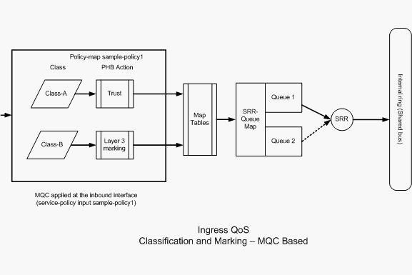 分类和标记 — 基于MQC
此图显示,策略映射应用于接口的输入端。在 Catalyst 3750 交换机中,不能将策略映射应用于任何接口的输出端。下一个配置将呈现该图。本部分不着重介绍 QoS 功能的排队功能。本部分仅重点介绍接口上应用的 MQC。
假设数据VLAN为10,子网地址为172.16.10.0/24,语音VLAN为100,子网地址为192.168.100.0/24。
!--- Section A

Distribution1(config)#ip access-list extended voice-traffic
Distribution1(config-std-nacl)#permit ip 192.168.100.0 0.0.0.255 any

Distribution1(config-std-nacl)#ip access-list extended
 database-application
Distribution1(config-ext-nacl)#permit tcp any any eq 1521
Distribution1(config-ext-nacl)#permit tcp any any eq 1810
Distribution1(config-ext-nacl)#permit tcp any any eq 2481
Distribution1(config-ext-nacl)#permit tcp any any eq 7778
Distribution1(config-ext-nacl)#exit

Distribution1(config)#class-map  Class-A
Distribution1(config-cmap)#match access-group name voice-traffic
Distribution1(config-cmap)#exit
Distribution1(config)#class-map  Class-B
Distribution1(config-cmap)#match access-group name
 database-application
Distribution1(config-cmap)#exit


!--- Section B

Distribution1(config)#policy-map sample-policy1
Distribution1(config-pmap)#class Class-A
Distribution1(config-pmap-c)#trust cos
Distribution1(config-pmap-c)#exit
Distribution1(config-pmap)#class Class-B
Distribution1(config-pmap-c)#set dscp af21
Distribution1(config-pmap-c)#exit
Distribution1(config-pmap)#exit


!--- Section C

Distribution1(config)#interface gigabitEthernet 1/0/13
Distribution1(config-if)#switchport access vlan 10
Distribution1(config-if)#switchport mode access
Distribution1(config-if)#switchport voice vlan 100
Distribution1(config-if)#spanning-tree portfast
Distribution1(config-if)#service-policy input sample-policy1
Distribution1(config-if)#exit
A 部分:
-
将 IP 电话数据流分类为 Class-A。IP 电话属于语音 VLAN,在 192.168.100.0 子网中具有 IP 地址。
-
将数据库应用程序数据流分类为 Class-B。通过端口号 1521、1810、2481、7778 发往任何目标的 PC 数据流(根据配置,实际上为任何数据流)被分类为 Class-B 类映射。
B 部分:
-
与 Class-A 匹配的数据流配置为信任 CoS 标签。这意味着信任来自 IP 电话的所有数据流的 CoS 值。如图所示,对于 Class-A 数据流,将从 CoS-DSCP 映射表获得 DSCP 值。
-
配置与Class-B匹配的流量以将DSCP值设置为AF21。如图所示,DCoS值从Class-B流量的DSCP-CoS映射表派生。
-
策略映射的各个类别下的配置称为 PHB 操作。在 Cisco 路由器中,支持的 PHB 操作包括标记、排队、策略、整形和拥塞避免。在 Cisco Catalyst 3750 交换机中,仅支持标记和策略 PHB 操作。
Distribution1(config)#policy-map test
Distribution1(config-pmap)#class test
Distribution1(config-pmap-c)#?
QoS policy-map class configuration commands:
  exit            Exit from QoS class action configuration mode
  no              Negate or set default values of a command
  police          Police
  service-policy  Configure QoS Service Policy
  set             Set QoS values
  trust           Set trust value for the class
  <cr>
set 和 trust 命令是标记 PHB 操作。可以配置 set 或 trust PHB 操作。在策略映射的一个类别中,不能同时配置这两项操作。但是,您可以在一个类中配置set,并在同一策略映射中信任另一个类。
police 命令是策略 PHB 操作。将在下一部分中详细讨论此命令。
Cisco Catalyst 3750 交换机不支持整形。Cisco Catalyst 3750 交换机支持排队和拥塞避免,但不能使用 MQC 进行配置。在本文档后面的部分中,将详细讨论排队和拥塞避免配置。
C 部分:
-
仅可将策略映射应用于接口的输入端。如果将其应用于接口的输出端,则会收到以下错误消息:
Distribution1(config)#interface gigabitethernet 1/0/3 Distribution1(config-if)#service-policy output test Warning: Assigning a policy map to the output side of an interface not supported Service Policy attachment failed Warning: Assigning a policy map to the output side of an interface not supported -
如果在端口 gi 1/0/3 上配置了任何其他 QoS 分类方法(例如,基于端口或基于 VLAN),则会在应用策略映射时删除这些配置。例如,端口 Gi 1/0/13 配置为信任 CoS,如下所示:
interface GigabitEthernet1/0/13
 description **** Access Port ****
 switchport access vlan 10
 switchport mode access
 switchport voice vlan 100
 mls qos cos 3
 mls qos trust cos
 spanning-tree portfast
-
将策略映射应用于该接口时,它会删除 trust 命令。
Distribution1(config)#interface gigabitethernet 1/0/13
Distribution1(config-if)#service-policy input sample-policy1
Distribution1(config-if)#do show run int gi 1/0/13
Building configuration...

Current configuration : 228 bytes
!
interface GigabitEthernet1/0/13
 description **** Access Port ****
 switchport access vlan 10
 switchport mode access
 switchport voice vlan 100
 service-policy input sample-policy1

!--- It replaces the mls qos trust or mls qos
!--- vlan-based command.

 mls qos cos 3

!--- This command is not removed.

 spanning-tree portfast
end
您可以看到,服务策略输入仅替换 mls qos trust 或 mls qos vlan-based 的命令。它不会更改其他命令,例如 mls qos cos 或 mls qos dscp-mutation 命令。总而言之,它将替换 QoS 分类命令,而不会替换 QoS 标记命令。
-
在策略映射中,只能看到两种类映射。Class-A 与 IP 电话数据流相匹配,而 Class-B 与来自 PC 的数据库应用程序数据流相匹配。所有其他 PC 数据流(访问列表中定义的数据库应用程序除外)将归类在策略映射的 class-default 类别下。这是一种全包容数据流,它将捕获与应用于策略映射的已定义类映射不匹配的所有数据流。因此,端口不信任属于class-default的此流量,并且这些数据包将默认CoS和DSCP标签设置为0。您可以配置为将任何默认CoS或DSCP值设置为此类默认流量。
可以使用 MQC 设置默认的 DSCP 值。从 DSCP-CoS 映射表获得 CoS 值。
Distribution1(config)#policy-map sample-policy1
Distribution1(config-pmap)#class class-default
Distribution1(config-pmap-c)#set dscp af13
Distribution1(config-pmap-c)#exit
可以设置默认的 CoS 值,如下所示。从 CoS-DSCP 映射表获得 DSCP 值。
Distribution1(config)#interface gigabitethernet 1/0/13
Distribution1(config-if)#mls qos cos 3
Distribution1(config-if)#do show run int gi 1/0/13
Building configuration...

Current configuration : 228 bytes
!
interface GigabitEthernet1/0/13
 description **** Access Port ****
 switchport access vlan 10
 switchport mode access
 switchport voice vlan 100
 service-policy input sample-policy1
 mls qos cos 3
 spanning-tree portfast
设置流量的最高优先级
在本示例中,配置用于设置来自TCP端口1494的流量的最高优先级。
-
需要为VOIP流量分配EF的DSCP值:
!--- Classifying all traffic coming with dscp value of EF
!--- under this class-map. Switch(config)#class-map match-all AutoQoS-VoIP-RTP-Trust Switch(config-cmap)#match ip dscp ef Switch(config)#policy-map AutoQoS-Police-CiscoPhone Switch(config-pmap)#class AutoQoS-VoIP-RTP-Trust !--- Again setting the dscp value back to EF. Switch(config-pmap-c)#set dscp ef Switch(config-pmap-c)#police 320000 8000 exceed-action policed-dscp-transmit -
需要为来自TCP 1494的流量分配DSCP值CS4:
Switch(config)#access-list 100 permit tcp -
所有其它流量都需要分配给CS3:
Switch(config)# access-list 200 permit ip any any

Switch(config)# class-map default
Switch(config-cmap)# match access-group 200

Switch(config)#policy-map AutoQoS-Police-CiscoPhone
Switch(config-pmap)#class default
Switch(config-pmap-c)#set dscp cs3
-
将其应用于相关接口下:
Switch(config)#interface
管制
在 Cisco Catalyst 3750 交换机上,只能在入站端口上配置策略。只能通过 MQC 配置策略。这意味着没有任何特定于接口的命令用来管制数据流。可以在策略映射中配置策略,并且可以仅使用 service-policy input <policy-name> 命令应用策略映射。不能将任何策略映射应用于接口的输出端。
Distribution1(config-if)#service-policy output test
police command is not supported for this interface
Configuration failed!
Warning: Assigning a policy map to the output side of an
         interface not supported.
本部分将讨论以下主题:
分类、标记和策略(超标操作 - drop)
本部分介绍丢弃过量的数据流的策略配置。策略测量传入的数据流,并将传入速率保持在配置的速率(比特/秒)。Cisco Catalyst 3750 交换机仅支持单速率、单桶策略。这意味着交换机仅在一个速率下进行测量,且能够以二种颜色(表示达标操作和超标操作)标记数据流的概况。下图显示了具有三个类映射的策略映射 sample-policy2。
本示例的要求如下:
-
将 ftp、pop3、imap 数据流管制为 10Mbps。
-
信任来自连接到 IP 电话的 PC 的 IP Communicator 应用程序数据包的 DSCP 值。同时,需要将此数据流管制为 1Mbps。
-
标记 filnet 应用程序并进行管制。
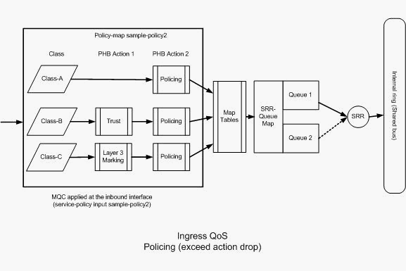 管制(超过操作丢弃)
以下配置体现了图中提及的策略映射:
!--- Create Access-list and Class map Class-A

Distribution1(config)#ip access-list extended BULK-DATA
Distribution1(config-ext-nacl)#permit tcp any any eq ftp
Distribution1(config-ext-nacl)#permit tcp any any eq ftp-data
Distribution1(config-ext-nacl)#permit tcp any any eq pop3
Distribution1(config-ext-nacl)#permit tcp any any eq 143
Distribution1(config-ext-nacl)#exit

Distribution1(config)#class-map Class-A
Distribution1(config-cmap)#match access-group name BULK-DATA
Distribution1(config-cmap)#exit


!--- Create Access-list and Class map Class-B

Distribution1(config)#ip access-list extended IP-Communicator
Distribution1(config-ext-nacl)#remark *** Voice Payload ***
Distribution1(config-ext-nacl)#permit udp any any range 16384 32767
Distribution1(config-ext-nacl)#remark *** Voice Signalling ***
Distribution1(config-ext-nacl)#permit tcp any any range 2000 2002
Distribution1(config-ext-nacl)#exit

Distribution1(config)#class-map Class-B
Distribution1(config-cmap)#match access-group name IP-Communicator
Distribution1(config-cmap)#exit


!--- Create Access-list and Class map Class-C

Distribution1(config)#ip access-list extended application
Distribution1(config-ext-nacl)#remark *** Application for example ***
Distribution1(config-ext-nacl)#permit tcp any any eq 32768
Distribution1(config-ext-nacl)#permit udp any any eq 32768
Distribution1(config-ext-nacl)#permit tcp any any eq 32769
Distribution1(config-ext-nacl)#permit udp any any eq 32769
Distribution1(config-ext-nacl)#exit

Distribution1(config)#class-map Class-C
Distribution1(config-cmap)#match access-group name application
Distribution1(config-cmap)#exit


!--- Create Policy map

Distribution1(config-cmap)#policy-map sample-policy2
Distribution1(config-pmap)#class Class-A
Distribution1(config-pmap-c)#police 10000000 8000 exceed-action drop
Distribution1(config-pmap-c)#class Class-B
Distribution1(config-pmap-c)#trust dscp
Distribution1(config-pmap-c)#police 256000 8000 exceed-action drop
Distribution1(config-pmap-c)#class Class-C
Distribution1(config-pmap-c)#set dscp CS2
Distribution1(config-pmap-c)#police 25000000 8000 exceed-action drop
Distribution1(config-pmap-c)#exit
Distribution1(config-pmap)#exit


!--- Apply Policy map to the interface

Distribution1(config)#interface GigabitEthernet1/0/20
Distribution1(config-if)#service-policy input sample-policy2
下面将解释策略映射中的配置:
-
Class-A:与Class A匹配的流量以10 Mbps的速率进行管制。不信任 Class A 数据流上的 QoS 标签。CoS和DSCP值标记为0。过量的数据包被监察器丢弃。
-
Class-B:对与B类匹配的流量执行两个PHB操作。一项操作是信任,另一项操作是策略。信任 Class-B 数据流的 DSCP 值。CoS值可以从DSCP-CoS表导出。然后,将 Class B 数据流的速率管制为 256 Kbps。监察器将丢弃过量的数据包。
-
Class-C:对与B类匹配的流量执行两个PHB操作。一项操作是标记,另一项操作是策略。与C类匹配的传入数据包使用DSCP值CS2进行标记,CoS值从DSCP-CoS表派生,该表为2。然后,C类流量以25 Mbps的速率受到管制。监察器将丢弃过量的数据包。
分类、标记和策略(超标操作 - policed-dscp-transmit)
本部分介绍标记并传输过量数据流的策略配置。下图显示了具有两个类映射的策略映射 sample-policy3:
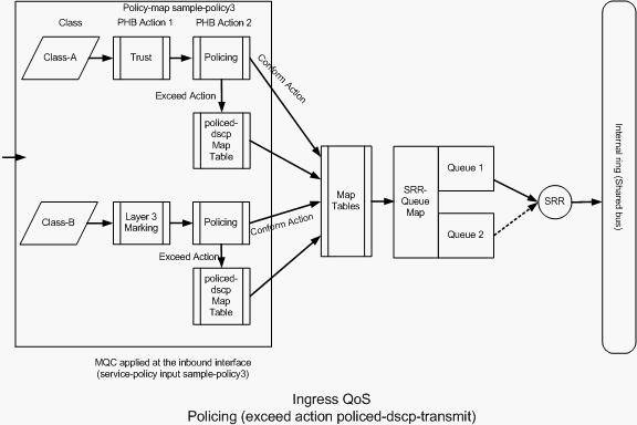 管制(Exceed Action policed-dscp-transmit)
交换机根据 policed-DSCP 映射表值对超出配置的管制速率的数据流进行标记。只有在策略配置中配置 policed-DSCP 映射后,才能使用该映射。下面列出了默认的 policed-DSCP 映射表:
Distribution1(config)#do show mls qos map policed-dscp
   Policed-dscp map:
     d1 :  d2 0  1  2  3  4  5  6  7  8  9
     ---------------------------------------
      0 :    00 01 02 03 04 05 06 07 08 09
      1 :    10 11 12 13 14 15 16 17 18 19
      2 :    20 21 22 23 24 25 26 27 28 29
      3 :    30 31 32 33 34 35 36 37 38 39
      4 :    40 41 42 43 44 45 46 47 48 49
      5 :    50 51 52 53 54 55 56 57 58 59
      6 :    60 61 62 63
从此表中可以发现,将会匹配到相同的 DSCP 值。例如,DSCP 34映射到DSCP 34。符合监察器速率的流量无需更改DSCP值即可传输。对于超出监察器速率的数据流,可以使用不同的 DSCP 值进行传输。例如,可以使用丢弃可能性更高的 DSCP 值进行标记。
如果使用默认的 policed-DSCP 值,则使用策略不会起到任何作用。例如,已在配置中将数据流的速率管制为 10 Mbps。传入数据包的DSCP值为CS4。如果保留默认DSCP值,则使用CS2的DSCP值传输符合10Mbps的流量。此外,使用DSCP值CS2传输超过10 Mbps的流量。这是因为policed-DSCP映射默认值映射相同的值。因此,建议正确地配置 policed-DSCP 映射表以区分 DSCP 值。
本示例的要求如下:
-
配置 policed-DSCP 映射表,设置下列映射:
-
EF 到 AF31
-
CS3 到 AF13
-
CS2 到 AF11
-
-
信任 IP Communicator 数据包的 DSCP 值并将其速率管制为 256Kbps。如果数据流超出 256Kbps,则使用 policed-DSCP 映射表重新标记 DSCP 值。
-
标记 filnet 应用程序并进行管制。如果数据流超出 25Mbps,则使用 policed-DSCP 映射表重新标记 DSCP 值。
以下配置体现了图中提及的策略映射:
!--- Policed DSCP table Configuration

Distribution1(config)#mls qos map policed-dscp 46 to 26
Distribution1(config)#mls qos map policed-dscp 24 to 14
Distribution1(config)#mls qos map policed-dscp 16 to 10


!--- Create Access-list and Class map Class-A

Distribution1(config)#ip access-list extended IP-Communicator
Distribution1(config-ext-nacl)#remark *** Voice Payload ***
Distribution1(config-ext-nacl)#permit udp any any range 16384 32767
Distribution1(config-ext-nacl)#remark *** Voice Signalling ***
Distribution1(config-ext-nacl)#permit tcp any any range 2000 2002
Distribution1(config-ext-nacl)#exit

Distribution1(config)#class-map Class-A
Distribution1(config-cmap)#match access-group name IP-Communicator
Distribution1(config-cmap)#exit


!--- Create Access-list and Class map Class-C

Distribution1(config)#ip access-list extended application
Distribution1(config-ext-nacl)#remark *** Application for example ***
Distribution1(config-ext-nacl)#permit tcp any any eq 32768
Distribution1(config-ext-nacl)#permit udp any any eq 32768
Distribution1(config-ext-nacl)#permit tcp any any eq 32769
Distribution1(config-ext-nacl)#permit udp any any eq 32769
Distribution1(config-ext-nacl)#exit

Distribution1(config)#class-map Class-B
Distribution1(config-cmap)#match access-group name application
Distribution1(config-cmap)#exit


!--- Create Policy map

Distribution1(config-cmap)#policy-map sample-policy3
Distribution1(config-pmap-c)#class Class-A
Distribution1(config-pmap-c)#trust dscp
Distribution1(config-pmap-c)#police 256000 8000 exceed-action policed-dscp-transmit
Distribution1(config-pmap-c)#class Class-B
Distribution1(config-pmap-c)#set dscp CS2
Distribution1(config-pmap-c)#police 25000000 8000 exceed-action policed-dscp-transmit
Distribution1(config-pmap-c)#exit
Distribution1(config-pmap)#exit


!--- Apply Policy map to the interface

Distribution1(config)#interface GigabitEthernet1/0/21
Distribution1(config-if)#service-policy input sample-policy3
下面将解释策略映射中的配置:
-
Policed-DSCP:policed-DSCP映射表中修改了三个值。
-
EF 到 AF31
-
CS3 到 AF13
-
CS2 到 AF11
前两个值是根据在 Class-A 和 Class-B 类映射中分类的数据流类型进行修改的。
-
-
Class-A:语音负载和来自软电话的语音控制在Class-A类映射中分类。语音负载流量的DSCP值为EF,语音控制的DSCP值为CS3。根据策略映射配置,这些DSCP值是受信任的。数据流的速率管制为 256 Kbps 速率。符合此速率的流量可以与传入DSCP值一起发送。超过此速率的流量可由管制的DSCP表重新标记并传输。管制的DSCP表可以根据配置的值将EF重新标记为AF31,将CS3重新标记为AF13。然后,可以从DSCP-CoS表导出对应的CoS值。
-
Class-B:与Class-B匹配的传入数据包使用CS2的DSCP值进行标记。Class-B流量以25 Mbps的速率受到管制。符合此速率的流量可以使用DSCP值2发送,而CoS值从DSCP-CoS表(即2)中导出。超过此速率的流量可由管制的DSCP表重新标记并传输。管制的DSCP表可以根据配置值将EF重新标记为AF31,将CS3重新标记为AF13。然后,可以从DSCP-CoS表导出对应的CoS值。
拥塞管理和避免
拥塞管理和避免过程包含三个步骤。这些步骤分别为排队、丢弃和调度。排队根据 QoS 标签将数据包放置到不同的软件队列。Cisco Catalyst 3750 交换机有两个入口队列。在使用 QoS 标签对数据流进行分类和标记后,可以根据 QoS 标签将数据流分配到两个不同的队列。
加权尾部丢弃(WTD)用于管理队列长度并为不同流量分类提供丢弃优先级。
入口队列和出口队列均由 SRR 提供服务,SRR 控制数据包的发送速率。在入口队列中,SRR 将数据包发送到堆栈环。SRR 可以在称为“整形”和“共享”的两种模式下操作。对于入口队列,默认模式为“共享”,并且这是支持的唯一模式。在共享模式下,队列根据配置的权重共享带宽。可以保证得到这一级别的带宽,但不限于这一级别的带宽。
本部分将介绍三种类型的配置。
可用于这些配置的命令如下:
Distribution1(config)#mls qos srr-queue input ?

!--- Queueing

  buffers         Configure buffer allocation
  cos-map         Configure cos-map for a queue id
  dscp-map        Configure dscp-map for a queue id

!--- Scheduling

  bandwidth       Configure SRR bandwidth
  priority-queue  Configure priority scheduling

!--- Dropping

  threshold       Configure queue tail-drop thresholds
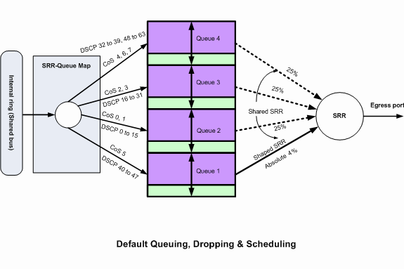
默认的排队、丢弃和调度配置
此输出显示队列映射的默认 QoS 标签。每个队列可以支持三种阈值级别。默认情况下,每个队列仅具有一种阈值,即 100%。
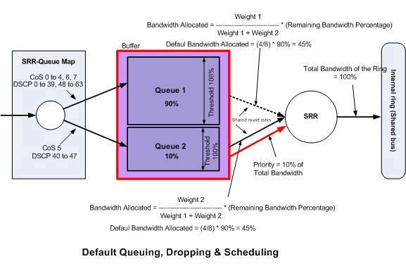 默认排队、丢弃和调度
-
默认队列映射配置:
具有CoS 5(DSCP 40到47)的数据包被放入队列2。剩余的数据包被放入队列1。
Distribution1#show mls qos maps cos-input-q
   Cos-inputq-threshold map:
              cos:  0   1   2   3   4   5   6   7
              ------------------------------------
  queue-threshold: 1-1 1-1 1-1 1-1 1-1 2-1 1-1 1-1

Distribution1#show mls qos maps dscp-input-q
   Dscp-inputq-threshold map:
     d1 :d2  0    1    2    3    4    5    6    7    8    9
     ------------------------------------------------------------
      0 :  01-01 01-01 01-01 01-01 01-01 01-01 01-01 01-01 01-01 01-01
      1 :  01-01 01-01 01-01 01-01 01-01 01-01 01-01 01-01 01-01 01-01
      2 :  01-01 01-01 01-01 01-01 01-01 01-01 01-01 01-01 01-01 01-01
      3 :  01-01 01-01 01-01 01-01 01-01 01-01 01-01 01-01 01-01 01-01
      4 :  02-01 02-01 02-01 02-01 02-01 02-01 02-01 02-01 01-01 01-01
      5 :  01-01 01-01 01-01 01-01 01-01 01-01 01-01 01-01 01-01 01-01
      6 :  01-01 01-01 01-01 01-01
下表显示了输入队列映射的默认 CoS/DSCP:
CoS DSCP 入口队列 0 0 到 7 1 1 8 到 15 1 2 16 到 23 1 3 24 到 31 1 4 32 到 39 1 5 40 到 47 2 6 48 到 55 1 7 56 到 63 1 -
默认队列配置:
入口队列缓冲区由 queue 1 共享 90%,而 queue 2 共享 10%。阈值级别 1、2 和 3 为 100%。
Distribution1#show mls qos input-queue
Queue     :       1       2
----------------------------------------------
buffers   :      90      10
bandwidth :       4       4
priority  :       0      10
threshold1:     100     100
threshold2:     100     100
-
默认调度程序配置:
Queue 2 为优先队列。SRR 根据所配置的权重(本例为 10%)为优先队列提供服务。然后,SRR与入口队列共享其余带宽(90%),并根据配置的权重为其提供服务。在本例中,queue 1 和 queue 2 均以 45% 的比率接受服务。
Distribution1#show mls qos input-queue
Queue     :       1       2
----------------------------------------------
buffers   :      90      10
bandwidth :       4       4
priority  :       0      10
threshold1:     100     100
threshold2:     100     100
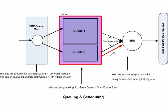
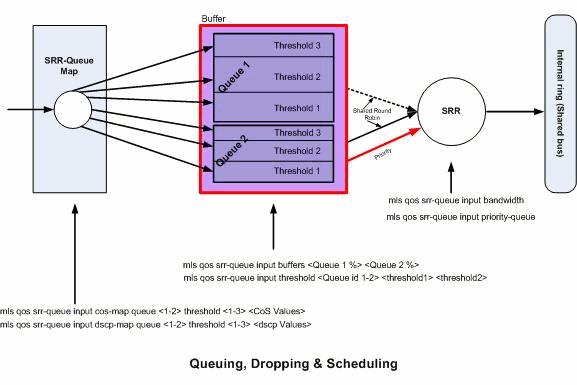
排队和调度
配置排队和调度分为三个步骤。这些步骤包括:
-
队列映射配置:
队列映射配置根据 DSCP 或 CoS 值将数据包映射到两个入口队列。
-
队列配置:
队列配置定义在两个队列之间划分入口缓冲区的比率(分配空间)。
-
调度程序配置:
SRR 配置用于控制将数据包从队列移至堆栈环的出列频率的加权比。
队列和调度程序配置控制在丢弃数据包前可缓冲的数据量。
 排队和调度
排队和调度
在本部分中,未配置 WTD 丢弃级别。这意味着如果队列为100%,则数据包可能会被丢弃。
-
队列映射配置:
首先,CoS 值将映射到队列。在本部分中,未配置阈值。
!--- Assign the frames into the queue based on the CoS value.

Distribution1(config)#mls qos srr-queue input cos-map queue 1 0 1
Distribution1(config)#mls qos srr-queue input cos-map queue 2 2 3 4 5 6 7


!--- Show output.

Distribution1#show mls qos maps cos-input-q
   Cos-inputq-threshold map:
              cos:  0   1   2   3   4   5   6   7
              ------------------------------------
  queue-threshold: 1-1 1-1 2-1 2-1 2-1 2-1 2-1 2-1

Distribution1#show mls qos maps dscp-input-q
   Dscp-inputq-threshold map:
     d1 :d2   0    1    2    3    4    5    6    7    8    9
     ------------------------------------------------------------
     0 :  01-01 01-01 01-01 01-01 01-01 01-01 01-01 01-01 01-01 01-01
     1 :  01-01 01-01 01-01 01-01 01-01 01-01 01-01 01-01 01-01 01-01
     2 :  01-01 01-01 01-01 01-01 01-01 01-01 01-01 01-01 01-01 01-01
     3 :  01-01 01-01 01-01 01-01 01-01 01-01 01-01 01-01 01-01 01-01
     4 :  02-01 02-01 02-01 02-01 02-01 02-01 02-01 02-01 01-01 01-01
     5 :  01-01 01-01 01-01 01-01 01-01 01-01 01-01 01-01 01-01 01-01
     6 :  01-01 01-01 01-01 01-01
您可以看到,在 Cos-inputq-threshold 和 Dscp-inputq-threshold 映射中存在冲突。例如,在 Cos-inputq-threshold 表中,CoS 3 映射到 queue 2。然而,在 Dscp-inputq-threshold 映射中,DSCP 值 24(对应于 CoS 3)映射到 queue 1。实际上,Dscp-inputq-threshold 映射将覆盖 Cos-inputq-threshold 映射。这些映射必须尽可能一致,以确保可预测的行为并简化故障排除。因此,将 Dscp-inputq-threshold 映射配置为与 Cos-inputq-threshold 映射同步。
!--- Assign the frames into the queue based on the DSCP value. Distribution1(config)#mls qos srr-queue input dscp-map queue 2 16 17 18 19 20 21 22 23 Distribution1(config)#mls qos srr-queue input dscp-map queue 2 24 25 26 27 28 29 30 31 Distribution1(config)#mls qos srr-queue input dscp-map queue 2 32 33 34 35 36 37 38 39 Distribution1(config)#mls qos srr-queue input dscp-map queue 2 48 49 50 51 52 53 54 55 Distribution1(config)#mls qos srr-queue input dscp-map queue 2 56 57 58 59 60 61 62 63 Distribution1#show mls qos maps dscp-input-q Dscp-inputq-threshold map: d1 :d2 0 1 2 3 4 5 6 7 8 9 ------------------------------------------------------------ 0 : 01-01 01-01 01-01 01-01 01-01 01-01 01-01 01-01 01-01 01-01 1 : 01-01 01-01 01-01 01-01 01-01 01-01 02-01 02-01 02-01 02-01 2 : 02-01 02-01 02-01 02-01 02-01 02-01 02-01 02-01 02-01 02-01 3 : 02-01 02-01 02-01 02-01 02-01 02-01 02-01 02-01 02-01 02-01 4 : 02-01 02-01 02-01 02-01 02-01 02-01 02-01 02-01 02-01 02-01 5 : 02-01 02-01 02-01 02-01 02-01 02-01 02-01 02-01 02-01 02-01 6 : 02-01 02-01 02-01 02-01 -
队列配置:
启用QoS后,Cisco IOS将缓冲区中的默认空间分配给队列入口数据包。两个入口队列(queue 1 和 queue 2)共享此缓冲区空间。在 Catalyst 3750 交换机中,可以配置每个队列可使用的此缓冲区空间的百分比。入口队列总可用内存的 67% 分配给 queue 1,33% 分配给 queue 2。
Distribution1(config)#mls qos srr-queue input buffers 67 33

Distribution1(config)#do show mls qos input
Queue     :       1       2
----------------------------------------------
buffers   :      67      33
bandwidth :       4       4
priority  :       0      10
threshold1:     100     100
threshold2:     100     100
-
调度程序配置:
此配置使用themls qos srr-queue input bandwidthcommand执行。在这里,此带宽表明队列上 SRR 服务的位数。
Distribution1(config)#mls qos srr-queue input bandwidth 90 10
Distribution1(config)#mls qos srr-queue input priority-queue 2
bandwidth 20

Distribution1(config)#do show mls qos input
Queue     :       1       2
----------------------------------------------
buffers   :      67      33
bandwidth :      90      10
priority  :       0      20
threshold1:     100     100
threshold2:     100     100
默认情况下,queue 2 为优先队列,并且总内环带宽的 10% 分配给优先队列。也可以将 queue 1 配置为优先队列。但不能将两个队列同时配置为优先队列。
-
如果环带宽达到 10Gbps,则 SRR 将 10Gbps 的 20% 提供给 queue 2,即 2 Gbps。剩余的8 Gbps环带宽由队列1和队列2共享。根据配置,队列1将获得8 Gbps的90%服务,而队列2将获得8 Gbps的10%服务。此 8 Gbps 带宽由 SRR 以共享模式提供。这意味着可以确保所配置的带宽百分比,但不限于此百分比。
注意:可以使用 mls qos srr-queue input priority-queue 2 bandwidth 0 命令禁用优先队列。
Distribution1(config)#do show mls qos input
Queue     :       1       2
----------------------------------------------
buffers   :      90      10
bandwidth :      90      10
priority  :       0       0
threshold1:     100     100
threshold2:     100     100
Distribution1(config)#
排队、丢弃和调度
在本部分中,除了配置队列缓冲区大小之外,还将配置 WTD 阈值级别。可以将流经交换机的各个数据包分配给队列以及阈值。
 排队、丢弃和调度
以下是配置示例和说明:
-
队列映射配置:
首先,CoS 值将映射到队列。
!--- Assign the frames into the queue based on the CoS value.

Distribution1(config)#mls qos srr-queue input cos-map queue 1 threshold 2  1
Distribution1(config)#mls qos srr-queue input cos-map queue 1 threshold 3  0
Distribution1(config)#mls qos srr-queue input cos-map queue 2 threshold 1  2
Distribution1(config)#mls qos srr-queue input cos-map queue 2 threshold 2  4 6 7
Distribution1(config)#mls qos srr-queue input cos-map queue 2 threshold 3  3 5


!--- Show output.

Distribution1(config)#do show mls qos maps cos-input-q
   Cos-inputq-threshold map:
              cos:  0   1   2   3   4   5   6   7
              ------------------------------------
  queue-threshold: 1-3 1-2 2-1 2-3 2-2 2-3 2-2 2-2

Distribution1(config)#do show mls qos maps dscp-input-q
   Dscp-inputq-threshold map:
     d1 :d2  0    1    2    3    4    5    6    7    8    9
     ------------------------------------------------------------
     0 :  01-01 01-01 01-01 01-01 01-01 01-01 01-01 01-01 01-01 01-01
     1 :  01-01 01-01 01-01 01-01 01-01 01-01 01-01 01-01 01-01 01-01
     2 :  01-01 01-01 01-01 01-01 01-01 01-01 01-01 01-01 01-01 01-01
     3 :  01-01 01-01 01-01 01-01 01-01 01-01 01-01 01-01 01-01 01-01
     4 :  02-01 02-01 02-01 02-01 02-01 02-01 02-01 02-01 01-01 01-01
     5 :  01-01 01-01 01-01 01-01 01-01 01-01 01-01 01-01 01-01 01-01
     6 :  01-01 01-01 01-01 01-01
您可以看到,在 Cos-inputq-threshold 和 Dscp-inputq-threshold 映射中存在冲突。例如,在 Cos-inputq-threshold 表中,CoS 3 映射到 queue 2,但在 Dscp-inputq-threshold 映射中,DSCP 值 24(对应于 CoS 3)映射到 queue 1。实际上,Dscp-inputq-threshold 映射将覆盖 Cos-inputq-threshold 映射。这些映射必须尽可能一致,以确保可预测的行为并简化故障排除。因此,将 Dscp-inputq-threshold 映射配置为与 Cos-inputq-threshold 映射同步。
!--- Assign the frames into the queue based on the DSCP value. Distribution1(config)#mls qos srr-queue input dscp-map queue 1 threshold 2 9 10 11 12 13 14 15 Distribution1(config)#mls qos srr-queue input dscp-map queue 1 threshold 3 0 1 2 3 4 5 6 7 Distribution1(config)#mls qos srr-queue input dscp-map queue 1 threshold 3 32 Distribution1(config)#mls qos srr-queue input dscp-map queue 2 threshold 1 16 17 18 19 20 21 22 23 Distribution1(config)#mls qos srr-queue input dscp-map queue 2 threshold 2 33 34 35 36 37 38 39 48 Distribution1(config)#mls qos srr-queue input dscp-map queue 2 threshold 2 49 50 51 52 53 54 55 56 Distribution1(config)#mls qos srr-queue input dscp-map queue 2 threshold 2 57 58 59 60 61 62 63 Distribution1(config)#mls qos srr-queue input dscp-map queue 2 threshold 3 24 25 26 27 28 29 30 31 Distribution1(config)#do show mls qos maps dscp-input-q Dscp-inputq-threshold map: d1 :d2 0 1 2 3 4 5 6 7 8 9 ------------------------------------------------------------ 0 : 01-03 01-03 01-03 01-03 01-03 01-03 01-03 01-03 01-01 01-02 1 : 01-02 01-02 01-02 01-02 01-02 01-02 02-01 02-01 02-01 02-01 2 : 02-01 02-01 02-01 02-01 02-03 02-03 02-03 02-03 02-03 02-03 3 : 02-03 02-03 01-03 02-02 02-02 02-02 02-02 02-02 02-02 02-02 4 : 02-03 02-03 02-03 02-03 02-03 02-03 02-03 02-03 02-02 02-02 5 : 02-02 02-02 02-02 02-02 02-02 02-02 02-02 02-02 02-02 02-02 6 : 02-02 02-02 02-02 02-02 -
队列配置:
默认情况下,阈值 3 为 100%,且不可更改。
Distribution1(config)#mls qos srr-queue input buffers 67 33
Distribution1(config)#mls qos srr-queue input threshold 1 8 16
Distribution1(config)#mls qos srr-queue input threshold 2 34 66

Distribution1(config)#do show mls qos input
Queue     :       1       2
----------------------------------------------
buffers   :      67      33
bandwidth :       4       4
priority  :       0      10
threshold1:       8      34
threshold2:      16      66
-
调度程序配置:
启用QoS后,Cisco IOS会在缓冲区中为每个入口端口分配默认空间。两个队列共享此缓冲区空间。在 Catalyst 3560/3750 交换机中,可以配置每个队列可使用的此缓冲区空间的百分比。
Distribution1(config)#mls qos srr-queue input bandwidth 90 10
Distribution1(config)#mls qos srr-queue input priority-queue 2 bandwidth 20

Distribution1(config)#do show mls qos input
Queue     :       1       2
----------------------------------------------
buffers   :      67      33
bandwidth :      90      10
priority  :       0      20
threshold1:       8      34
threshold2:      16      66
默认情况下,queue 2 为优先队列,并且总内环带宽的 10% 分配给优先队列。也可以将 queue 1 配置为优先队列。但不能将两个队列同时配置为优先队列。
如果环带宽达到 10Gbps,则 SRR 将 10Gbps 的 20% 提供给 queue 2,即 2 Gbps。剩余的 8 Gbps 环带宽由 queue 1 和 queue 2 共享。根据配置,queue 1 使用 8Gbps 的 90%,而 queue 2 再使用 8 Gbps 的 10%。此 8 Gbps 带宽由 SRR 以共享模式提供。这意味着可以确保所配置的带宽百分比,但不限于此百分比。
注意:可以使用 mls qos srr-queue input priority-queue 2 bandwidth 0 命令禁用优先队列。
Distribution1(config)#do show mls qos input
Queue     :       1       2
----------------------------------------------
buffers   :      90      10
bandwidth :      90      10
priority  :       0       0
threshold1:     100     100
threshold2:     100     100
Distribution1(config)#
出口 QoS 功能
Cisco Catalyst 3750 交换机支持“拥塞管理和避免”出口 QoS 功能。拥塞管理和避免过程包含三个步骤。这些步骤分别为排队、丢弃和调度。
排队根据 QoS 标签将数据包放置到不同的软件队列。Cisco Catalyst 3750 交换机有 4 个出口队列,每个队列有 3 个阈值。在使用 QoS 标签对数据流进行分类和标记后,可以根据 QoS 标签将数据流分配到四个不同的队列。
可以为每个队列配置缓冲区大小、后备阈值、阈值级别和最大阈值。加权尾部丢弃(WTD)用于管理队列长度并为不同流量分类提供丢弃优先级。入口队列参数全局配置。不能按端口逐个配置入口队列参数。但出口队列参数按端口逐个进行配置。即便如此,配置也是按端口进行的。不能为每个端口配置不同的设置。可以采用两种不同的方式配置每个端口。这称为队列集。可以在全局配置中最多配置两个不同的队列集。然后,可以在接口上应用这两个队列集之一。
入口队列和出口队列均由 SRR 提供服务,SRR 控制数据包的发送速率。在入口队列中,SRR 将数据包发送到堆栈环。SRR 可以在称为“整形”和“共享”的两种模式下操作。对于入口队列,默认模式为“共享”,并且这是支持的唯一模式。在共享模式下,队列根据配置的权重共享它们之间的带宽。可以保证得到这一级别的带宽,但不限于这一级别的带宽。在整形模式下,会保证出口队列的带宽百分比,并限制为该比率。整形的数据流不能使用比分配的带宽更多的带宽,即使链路处于空闲状态也是如此。随着时间的推移,整形可以提供更平稳的数据流,并减少突发数据流的高峰和低谷。可以将 Queue 1 配置为优先队列。
出口 QoS 命令
本部分对所有可用的出口 QoS 命令进行分类。
-
队列映射配置:
要将 CoS 值映射到出口队列,请使用以下命令:
Rack1SW1(config)#mls qos srr-queue output cos-map queue ?
  <1-4>  enter cos-map output queue id

Rack1SW1(config)#mls qos srr-queue output cos-map queue 1
 threshold ? <1-3>  enter cos-map threshold id

Rack1SW1(config)#mls qos srr-queue output cos-map queue 1
 threshold 1 ? <0-7>  8 cos values separated by spaces
要将 DSCP 值映射到出口队列,请使用以下命令:
Rack1SW1(config)#mls qos srr-queue output dscp-map queue ? <1-4> enter dscp-map output queue id Rack1SW1(config)#mls qos srr-queue output dscp-map queue 1 threshold ?
<1-3> enter dscp-map threshold id Rack1SW1(config)#mls qos srr-queue output dscp-map queue 1threshold 1 ?
<0-63> dscp values separated by spaces (up to 8 values total) -
队列配置:
出口队列配置允许配置两个队列集。每个队列集都具有相关选项,用于为四个出口队列配置缓冲大小和阈值。然后,可以将任何一个队列集应用于任何一个端口。当在交换机上启用 QoS 后,默认情况下,queue set 1 将分配给所有端口。
Rack1SW1(config)#mls qos queue-set output ?
  <1-2>  queue-set id

Rack1SW1(config)#mls qos queue-set output 1 ?
  buffers    assign buffers to each egress queue
  threshold  Assign threshold values to a queue
要为所有四个出口队列配置缓冲大小,请使用以下命令:
Rack1SW1(config)#mls qos queue-set output 1 buffers ?
  <0-99>  enter buffer percentage for queue 1 0-99

Rack1SW1(config)#mls qos queue-set output 1 buffers 10 ?
  <1-100>  enter buffer percentage for queue 2 1-100
 (includes CPU buffer)

Rack1SW1(config)#mls qos queue-set output 1 buffers 10 20 ?
  <0-99>  enter buffer percentage for queue 3 0-99

Rack1SW1(config)#mls qos queue-set output 1 buffers 10 20 30 ?
  <0-99>  enter buffer percentage for queue 4 0-99
要为每个队列配置两个阈值(后备阈值和最大阈值)(默认情况下,阈值 3 为 100%,且不可更改),请使用以下命令:
Rack1SW1(config)#mls qos queue-set output 1 threshold ?
  <1-4>  enter queue id in this queue set

Rack1SW1(config)#mls qos queue-set output 1 threshold 1 ?
  <1-400>  enter drop threshold1 1-400

Rack1SW1(config)#mls qos queue-set output 1 threshold 1 50 ?
  <1-400>  enter drop threshold2 1-400

Rack1SW1(config)#mls qos queue-set output 1 threshold 1 50 60 ?
  <1-100>  enter reserved threshold 1-100

Rack1SW1(config)#mls qos queue-set output 1 threshold 1 50 60 100 ?
  <1-400>  enter maximum threshold 1-400
要将队列集应用于接口(当在交换机上启用 qos 后,默认情况下,queue set 1 将分配给所有端口),请使用以下命令:
Rack1SW1(config-if)#queue-set ?
  <1-2>  the qset to which this port is mapped
-
调度程序配置:
可以为交换机接口使用三种不同的配置。这些配置为带宽整形、共享和限制。也可以将 egress queue 1 配置为优先队列。如果启用了优先级队列,则SRR会在为其他三个队列提供服务之前为其提供服务,直到其为空。但在入口优先队列中,SRR 使用所配置的值为优先队列提供服务。
Rack1SW1(config-if)#srr-queue bandwidth ?
  limit  Configure bandwidth-limit for this interface
  shape  Configure shaping on transmit queues
  share  Configure shared bandwidth

Rack1SW1(config-if)#priority-queue ?
  out  egress priority queue
带宽限制配置:
Rack1SW1(config-if)#srr-queue bandwidth limit ?
  <10-90>  enter bandwidth limit for interface  as percentage
带宽整形配置:
Rack1SW1(config-if)#srr-queue bandwidth shape ?
  <0-65535>  enter bandwidth weight for queue id 1

Rack1SW1(config-if)#srr-queue bandwidth shape 10 ?
  <0-65535>  enter bandwidth weight for queue id 2

Rack1SW1(config-if)#srr-queue bandwidth shape 10 20 ?
  <0-65535>  enter bandwidth weight for queue id 3

Rack1SW1(config-if)#srr-queue bandwidth shape 10 20 30 ?
  <0-65535>  enter bandwidth weight for queue id 4
带宽共享配置:
Rack1SW1(config-if)#srr-queue bandwidth share ?
  <1-255>  enter bandwidth weight for queue id 1

Rack1SW1(config-if)#srr-queue bandwidth share 10 ?
  <1-255>  enter bandwidth weight for queue id 2

Rack1SW1(config-if)#srr-queue bandwidth share 10 20 ?
  <1-255>  enter bandwidth weight for queue id 3

Rack1SW1(config-if)#srr-queue bandwidth share 10 20 30 ?
  <1-255>  enter bandwidth weight for queue id 4
除非启用优先队列,否则全部四个队列都将加入 SRR,在这种情况下,将忽略第一个带宽权重,并且在比率计算也不使用第一个带宽权重。在为其他队列服务前,将始终为优先队列提供服务,直至该队列为空。通过使用 priority-queue out 接口配置命令,可以启用优先队列。
默认配置
默认队列映射配置
 默认排队、丢弃和调度2
以下默认映射可根据需要进行更改:
!--- Map CoS to Egress Queue

Distribution1#show mls qos maps cos-output-q
   Cos-outputq-threshold map:
              cos:  0   1   2   3   4   5   6   7
              ------------------------------------
  queue-threshold: 2-1 2-1 3-1 3-1 4-1 1-1 4-1 4-1


!--- Map DSCP to Egress Queue

Distribution1#show mls qos maps dscp-output-q
   Dscp-outputq-threshold map:
     d1 :d2  0    1    2    3    4    5    6    7    8    9
     ------------------------------------------------------------
     0 :  02-01 02-01 02-01 02-01 02-01 02-01 02-01 02-01 02-01 02-01
     1 :  02-01 02-01 02-01 02-01 02-01 02-01 03-01 03-01 03-01 03-01
     2 :  03-01 03-01 03-01 03-01 03-01 03-01 03-01 03-01 03-01 03-01
     3 :  03-01 03-01 04-01 04-01 04-01 04-01 04-01 04-01 04-01 04-01
     4 :  01-01 01-01 01-01 01-01 01-01 01-01 01-01 01-01 04-01 04-01
     5 :  04-01 04-01 04-01 04-01 04-01 04-01 04-01 04-01 04-01 04-01
     6 :  04-01 04-01 04-01 04-01
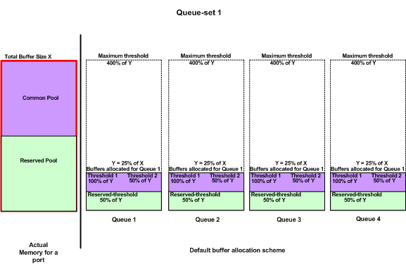
默认队列配置
 默认缓冲区分配方案
出口队列默认设置适用于大多数场合。只有在您完全了解出口队列并且这些设置不符合您的QoS解决方案时,您才能更改这些设置。
默认情况下,将配置两个队列集,并将 queue set 1 分配给所有端口。为每个队列分配总缓冲区空间的 25%。每个队列保留所分配的缓冲区空间的 50%,即总缓冲区空间的 12.5%。所有后备缓冲区的总和表示后备池,剩余的缓冲区是公用池的一部分。默认配置将此队列可拥有的最大内存量设置为 400%,超过此最大内存量后,将丢弃数据包。
Distribution1#show mls qos queue-set 1
Queueset: 1
Queue     :       1       2       3       4
----------------------------------------------
buffers   :      25      25      25      25
threshold1:     100     200     100     100
threshold2:     100     200     100     100
reserved  :      50      50      50      50
maximum   :     400     400     400     400

Distribution1#show mls qos queue-set 2
Queueset: 2
Queue     :       1       2       3       4
----------------------------------------------
buffers   :      25      25      25      25
threshold1:     100     200     100     100
threshold2:     100     200     100     100
reserved  :      50      50      50      50
maximum   :     400     400     400     400

Distribution1#show mls qos int gigabitEthernet 1/0/20 buffers
GigabitEthernet1/0/20
The port is mapped to qset : 1
The allocations between the queues are : 25 25 25 25
默认调度程序配置:
优先队列处于禁用状态。同时为 SRR 配置整形和共享模式。整形模式权重将覆盖共享模式值。因此,最终结果是,以整形模式为 queue 1 提供服务,以共享模式为 queue 2、3 和 4 提供服务。这意味着将使用一个绝对带宽百分比值(1/25 或百分之四)为 queue 1 提供服务。使用 25% 的带宽为 Queue 2、3 和 4 提供服务。如果带宽可用,为 queue 2、3 和 4 提供服务的带宽可以超过总带宽的 25%。
Distribution1#show mls qos int gigabitEthernet 1/0/20 queueing
GigabitEthernet1/0/20
Egress Priority Queue : disabled
Shaped queue weights (absolute) :  25 0 0 0
Shared queue weights  :  25 25 25 25
The port bandwidth limit : 100  (Operational Bandwidth:100.0)
The port is mapped to qset : 1
排队、丢弃和调度
以下为示例配置:
-
队列映射配置:
Rack1SW1(config)#mls qos srr-queue output cos-map queue 1 threshold 3 5
Rack1SW1(config)#mls qos srr-queue output cos-map queue 1 threshold 1 2 4
Rack1SW1(config)#mls qos srr-queue output cos-map queue 2 threshold 2 3
Rack1SW1(config)#mls qos srr-queue output cos-map queue 2 threshold 3 6 7
Rack1SW1(config)#mls qos srr-queue output cos-map queue 3 threshold 3 0
Rack1SW1(config)#mls qos srr-queue output cos-map queue 4 threshold 3 1
Rack1SW1(config)#mls qos srr-queue output dscp-map queue 1 threshold 3  46
Rack1SW1(config)#mls qos srr-queue output dscp-map queue 2 threshold 1  16
Rack1SW1(config)#mls qos srr-queue output dscp-map queue 2 threshold 1  18 20 22
Rack1SW1(config)#mls qos srr-queue output dscp-map queue 2 threshold 1  25
Rack1SW1(config)#mls qos srr-queue output dscp-map queue 2 threshold 1  32
Rack1SW1(config)#mls qos srr-queue output dscp-map queue 2 threshold 1  34 36 38
Rack1SW1(config)#mls qos srr-queue output dscp-map queue 2 threshold 2  24 26
Rack1SW1(config)#mls qos srr-queue output dscp-map queue 2 threshold 3  48 56
Rack1SW1(config)#mls qos srr-queue output dscp-map queue 3 threshold 3  0
Rack1SW1(config)#mls qos srr-queue output dscp-map queue 4 threshold 1  8
Rack1SW1(config)#mls qos srr-queue output dscp-map queue 4 threshold 3  10 12 14
-
队列配置:
以下配置显示了 queue set 1 和 2 的配置。默认情况下,queue set 1 应用于所有接口。
Rack1SW3(config)#mls qos queue-set output 1 buffers 10 10 26 54
Rack1SW3(config)#mls qos queue-set output 2 buffers 16 6 17 61
Rack1SW3(config)#mls qos queue-set output 1 threshold 2 70 80 100 100
Rack1SW3(config)#mls qos queue-set output 1 threshold 4 40 100 100 100

Rack1SW3(config)#mls qos queue-set output 2 threshold 1 149 149 100 149
Rack1SW3(config)#mls qos queue-set output 2 threshold 2 118 118 100 235
Rack1SW3(config)#mls qos queue-set output 2 threshold 3 41 68 100 272
Rack1SW3(config)#mls qos queue-set output 2 threshold 4 42 72 100 242
Rack1SW3(config)#interface fastethernet 1/0/11
Rack1SW3(config-if)#queue-set 2
queue set 2 应用于接口 1/0/11。
Rack1SW3(config-if)#do show mls qos interface fastethernet 1/0/10 buffers
FastEthernet1/0/10
The port is mapped to qset : 1
The allocations between the queues are : 10 10 26 54

Rack1SW3(config-if)#do show mls qos interface fastethernet 1/0/11 buffers
FastEthernet1/0/11
The port is mapped to qset : 2
The allocations between the queues are : 16 6 17 61
-
调度程序配置:
Rack1SW3(config-if)#srr-queue bandwidth share 1 75 25 5
Rack1SW3(config-if)#srr-queue bandwidth shape  3  0  0  0
Cisco Catalyst 3750出口队列不支持低延迟队列(LLQ)。 它支持优先队列。配置 priority-queue out 后,如果 queue 1 具有数据包,则始终为该队列提供服务。
Rack1SW3(config-if)#srr-queue bandwidth share 1 75 25 5
Rack1SW3(config-if)#srr-queue bandwidth shape  3  0  0  0
Rack1SW3(config-if)#priority-queue out
当您配置此命令时,SRR权重和队列大小比率会受到影响,因为加入SRR的队列会少一个。这意味着忽略srr-queue bandwidth shape或srr-queue bandwidth share命令中的weight1(不在比率计算中使用)。
以下为查看特定队列上的丢包的命令:
步骤 1:
1/ #show platform pm if-numbers
使用show platform pm if-numbers命令并检查与您的接口(这是3750上的传出接口)对应的端口信息。 例如,fas 0/3可以是端口0/4。保留4作为端口值;如果第一个值不是零,则请在端口号后给出asic号。
interface gid gpn lpn port slot unit slun port-type lpn-idb gpn-idb
------------------------------------------------------------------------
---------
Gi0/1     1    1    25   0/1  1    1    1    local     Yes     Yes
Gi0/2     2    2    26   0/0  1    2    2    local     Yes     Yes
Fa0/1     3    3    1    0/2  1    1    3    local     Yes     Yes
Fa0/2     4    4    2    0/3  1    2    4    local     Yes     Yes
Fa0/3     5    5    3    0/4  1    3    5    local     Yes     Yes
Fa0/4     6    6    4    0/5  1    4    6    local     Yes     Yes
Fa0/5     7    7    5    0/6  1    5    7    local     Yes     Yes
Fa0/6     8    8    6    0/7  1    6    8    local     Yes     Yes
与接口fa 0/3对应的端口值为0/4。现在您可以使用show platform port-asic stats drop port 4命令查看接口fa 0/3的队列丢弃。
2/ #show platform port-asic stats drop port 4

Port-asic Port Drop Statistics - Summary
========================================
  RxQueue 0 Drop Stats: 0
  RxQueue 1 Drop Stats: 0
  RxQueue 2 Drop Stats: 0
  RxQueue 3 Drop Stats: 0
...

  Port 4 TxQueue Drop Statistics
    Queue 0
      Weight 0 Frames 0
      Weight 1 Frames 0
      Weight 2 Frames 0
    Queue 1
      Weight 0 Frames 0
      Weight 1 Frames 2755160   <--- Here is an example of drops
      Weight 2 Frames 0
    Queue 2
      Weight 0 Frames 0
      Weight 1 Frames 0
      Weight 2 Frames 0
    Queue 3
      Weight 0 Frames 0
      Weight 1 Frames 0
      Weight 2 Frames 8
步骤 2:
-
带宽限制配置:
要限制端口的最大输出速率,请配置 srr-queue bandwidth limit 接口配置命令。如果将此命令配置为 80%,则端口的空闲时间为 20%。线路速率将下降到连接速度的 80%。由于硬件将以六为增量调整线路速率,因此这些值并非精确值。此命令在万兆以太网接口上不可用。
srr-queue bandwidth limit weight1其中weight1是端口必须限制到的端口速度的百分比。范围是 10 到 90。
注意:出口队列默认设置适用于大多数场合。只有在您完全了解出口队列并且这些设置不符合您的服务质量(QoS)解决方案时,您才能更改这些设置。
相关信息
修订历史记录
| 版本 | 发布日期 | 备注 |
|---|---|---|
2.0 |
31-May-2023
|
重新认证 |
1.0 |
17-May-2007
|
初始版本 |
 反馈
反馈