配置到Azure的ASA IPsec VTI连接

简介
本文档介绍如何配置到Azure的自适应安全设备(ASA)IPsec虚拟隧道接口(VTI)连接。
先决条件
要求
Cisco 建议您了解以下主题:
- 使用运行ASA 9.8.1或更高版本的公共静态IPv4地址直接连接到互联网的ASA
- Azure帐户
使用的组件
本文档不限于特定的软件和硬件版本。
本文档中的信息都是基于特定实验室环境中的设备编写的。本文档中使用的所有设备最初均采用原始(默认)配置。如果您的网络处于活动状态,请确保您了解所有命令的潜在影响。
背景信息
在ASA 9.8.1中,IPsec VTI功能已扩展为使用IKEv2,但是,它仍然仅限于sVTI IPv4 over IPv4。此配置指南是使用ASA CLI接口和Azure门户生成的。Azure门户的配置也可以通过PowerShell或使用API执行。有关Azure配置方法的详细信息,请参阅Azure文档。

注意:目前,仅在单情景路由模式下支持VTI。
配置
本指南假设尚未配置Azure云。如果资源已建立,则可以跳过其中一些步骤。
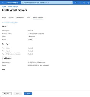
步骤1.在Azure中配置网络
这是居住在Azure云中的网络地址空间。此地址空间必须足够大,以容纳其中的子网,如图所示。
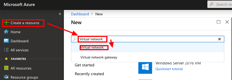
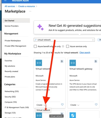
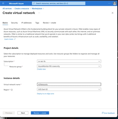 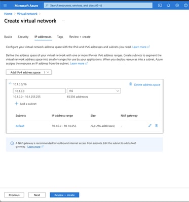  |
|
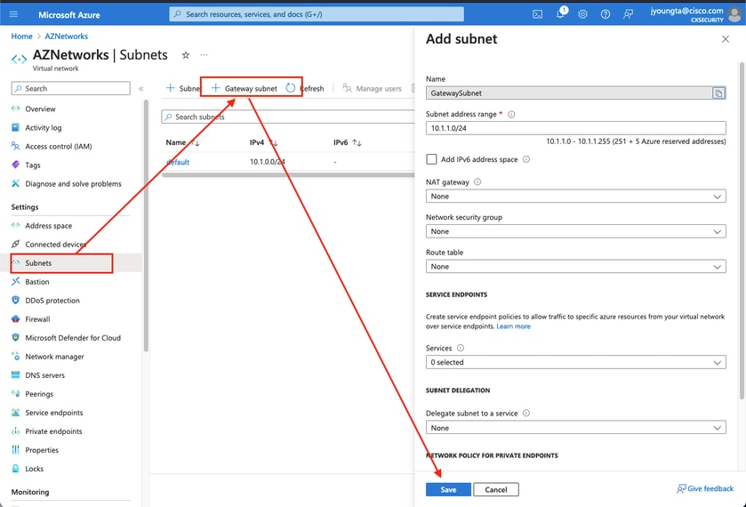
步骤2.修改虚拟网络以创建网关子网
1.导航到虚拟网络并添加网关子网。在本示例中,使用的是 10.1.1.0/24。
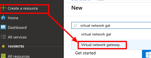
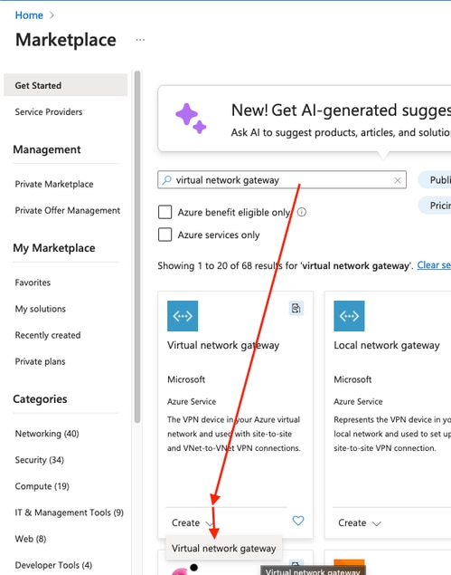
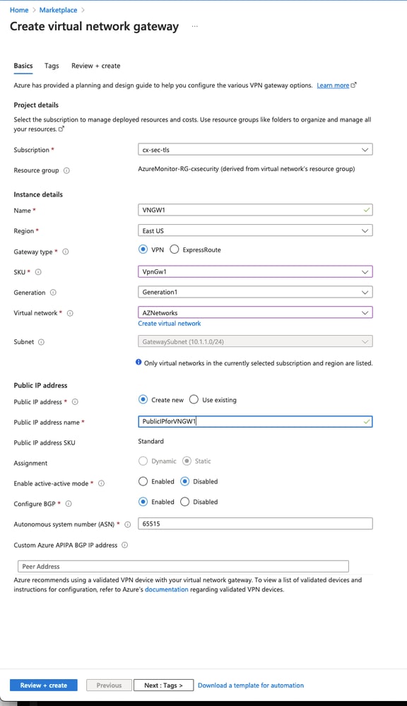
步骤3.创建虚拟网络网关
1.这是托管在云中的VPN终端。这是ASA用来构建IPsec隧道的设备。此步骤还会创建一个公共IP,将其分配给虚拟网络网关。完成此步骤可能需要15 - 20分钟。
 |
|
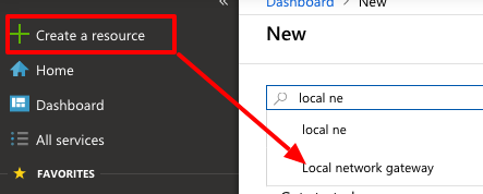
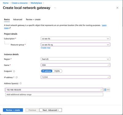
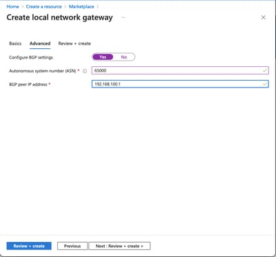
步骤4.创建本地网络网关
1.本地网络网关是代表ASA的资源。
  |
|
步骤5.在虚拟网络网关和本地网络网关之间创建新连接,如图所示
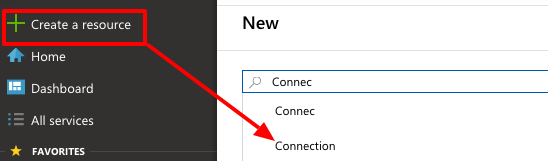
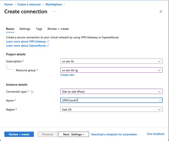
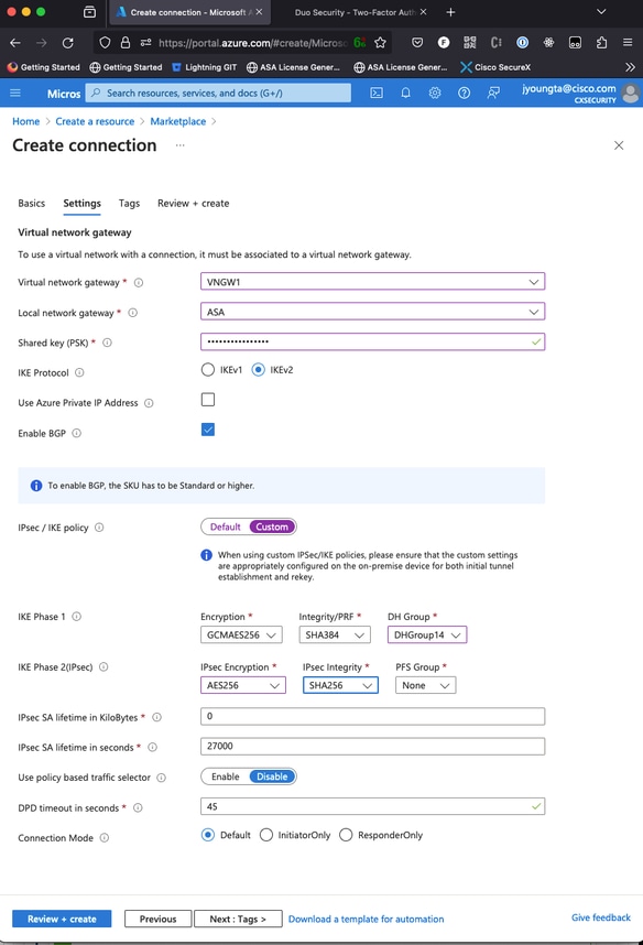
步骤6.配置ASA
1.首先,在外部接口上启用IKEv2并配置IKEv2策略。
crypto ikev2 policy 10
 encryption aes-gcm-256 aes-gcm-192 aes-gcm
 integrity null
 group 14 5 2
 prf sha512 sha384 sha256 sha
 lifetime seconds 86400
crypto ikev2 policy 20
 encryption aes-256 aes-192 aes
 integrity sha512 sha384 sha256 sha
 group 14 5 2
 prf sha512 sha384 sha256 sha
 lifetime seconds 86400
crypto ikev2 enable outside
步骤6.配置IPsec转换集和IPsec配置文件
crypto ipsec ikev2 ipsec-proposal AZURE-PROPOSAL
 protocol esp encryption aes-256
 protocol esp integrity sha-256
crypto ipsec profile AZURE-PROPOSAL
 set ikev2 ipsec-proposal AZURE-PROPOSAL
步骤7.配置tunnel-group。
1.检索步骤3中创建的虚拟网络网关的公有IPv4地址,如图所示。
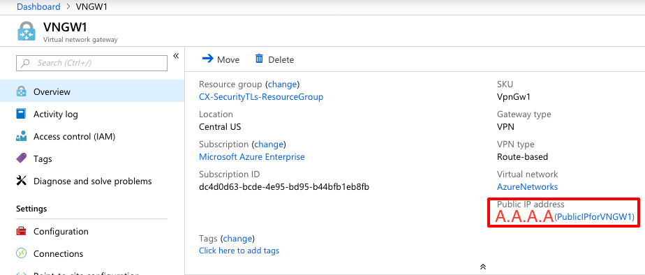
2.然后,使用步骤3中定义的预共享密钥在ASA上配置group-policy和tunnel-group。
group-policy AZURE internal
group-policy AZURE attributes
 vpn-tunnel-protocol ikev2
tunnel-group A.A.A.A type ipsec-l2l
tunnel-group A.A.A.A general-attributes
 default-group-policy AZURE
tunnel-group A.A.A.A ipsec-attributes
 ikev2 remote-authentication pre-shared-key *****
 ikev2 local-authentication pre-shared-key *****
步骤8.配置隧道接口
1.在第4步中,为已配置的BGP连接配置本地网络网关、网络地址和IP地址。即要在VTI上配置的IP地址和网络。
interface Tunnel1
 nameif AZURE
 ip address 192.168.100.1 255.255.255.252
 tunnel source interface outside
 tunnel destination A.A.A.A
 tunnel mode ipsec ipv4
 tunnel protection ipsec profile AZURE-PROPOSAL
 no shutdown
2. 选项1.使用BGP配置Azure的动态路由交换路由。
2a..在Azure中找到BGP路由器的IP地址,以查看步骤3中创建的虚拟网络网关的配置。在本示例中,该地址为10.1.2.254。
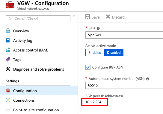
3.在ASA上,配置通过VTI隧道指向10.1.2.254的静态路由。在本示例中,192.168.100.2与VTI位于同一子网内。虽然没有设备具有该IP地址,但ASA会安装指向VTI接口的路由。
route AZURE 10.1.2.254 255.255.255.255 192.168.100.2 1
4.然后,在ASA上配置BGP。网络192.168.2.0/24是ASA内部接口以及传播到云的路由。此外,在Azure中配置的网络会通告给ASA。
router bgp 65000
 bgp log-neighbor-changes
 bgp graceful-restart
 address-family ipv4 unicast
  neighbor 10.1.2.254 remote-as 65515
  neighbor 10.1.2.254 ebgp-multihop 255
  neighbor 10.1.2.254 activate
  network 192.168.2.0
  network 192.168.100.0 mask 255.255.255.252
  no auto-summary
  no synchronization
 exit-address-family
选项2.配置静态路由,在ASA和Azure上静态配置路由。将ASA配置为通过VTI隧道向Azure网络发送流量。
route AZURE 10.1.0.0 255.255.0.0 192.168.100.2 1
1.使用位于ASA后面的网络和隧道接口上的子网修改步骤4中创建的本地网络网关。然后,在Add Additional Network Spaces部分下面添加前缀。
验证
使用本部分可确定配置能否正常运行。
步骤1.通过运行show crypto ikev2 sa命令验证IKEv2会话是否已建立。
ciscoasa# show crypto ikev2 sa

IKEv2 SAs:

Session-id:6, Status:UP-ACTIVE, IKE count:1, CHILD count:1

Tunnel-id Local                                               Remote                                                  Status         Role
2006974029 B.B.B.B.    /500                                   A.A.A.A/500                                             READY          INITIATOR
      Encr: AES-CBC, keysize: 256, Hash: SHA96, DH Grp:2, Auth sign: PSK, Auth verify: PSK
      Life/Active Time: 86400/4640 sec
Child sa: local selector  0.0.0.0/0 - 255.255.255.255/65535
          remote selector 0.0.0.0/0 - 255.255.255.255/65535
          ESP spi in/out: 0x74e90416/0xba17723a
步骤2.通过运行show crypto ipsec sa命令验证是否也协商了IPsec SA。
ciscoasa# show crypto ipsec sa
interface: AZURE
    Crypto map tag: __vti-crypto-map-3-0-1, seq num: 65280, local addr: B.B.B.B

      local ident (addr/mask/prot/port): (0.0.0.0/0.0.0.0/0/0)
      remote ident (addr/mask/prot/port): (0.0.0.0/0.0.0.0/0/0)
      current_peer: A.A.A.A


      #pkts encaps: 240, #pkts encrypt: 240, #pkts digest: 240
      #pkts decaps: 377, #pkts decrypt: 377, #pkts verify: 377
      #pkts compressed: 0, #pkts decompressed: 0
      #pkts not compressed: 240, #pkts comp failed: 0, #pkts decomp failed: 0
      #pre-frag successes: 0, #pre-frag failures: 0, #fragments created: 0
      #PMTUs sent: 0, #PMTUs rcvd: 0, #decapsulated frgs needing reassembly: 0
      #TFC rcvd: 0, #TFC sent: 0
      #Valid ICMP Errors rcvd: 0, #Invalid ICMP Errors rcvd: 0
      #send errors: 0, #recv errors: 0

      local crypto endpt.: B.B.B.B/500, remote crypto endpt.: A.A.A.A/500
      path mtu 1500, ipsec overhead 78(44), media mtu 1500
      PMTU time remaining (sec): 0, DF policy: copy-df
      ICMP error validation: disabled, TFC packets: disabled
      current outbound spi: BA17723A
      current inbound spi : 74E90416

    inbound esp sas:
      spi: 0x74E90416 (1961427990)
         SA State: active
         transform: esp-aes-256 esp-sha-256-hmac no compression
         in use settings ={L2L, Tunnel, IKEv2, VTI, }
         slot: 0, conn_id: 1722, crypto-map: __vti-crypto-map-3-0-1
         sa timing: remaining key lifetime (kB/sec): (3962863/24100)
         IV size: 16 bytes
         replay detection support: Y
         Anti replay bitmap:
          0xFFFFFFFF 0xFFFFFFFF
    outbound esp sas:
      spi: 0xBA17723A (3122098746)
         SA State: active
         transform: esp-aes-256 esp-sha-256-hmac no compression
         in use settings ={L2L, Tunnel, IKEv2, VTI, }
         slot: 0, conn_id: 1722, crypto-map: __vti-crypto-map-3-0-1
         sa timing: remaining key lifetime (kB/sec): (4008947/24100)
         IV size: 16 bytes
         replay detection support: Y
         Anti replay bitmap:
          0x00000000 0x00000001

ciscoasa#
步骤3.如果使用静态路由,请运行ping and ping tcp命令验证BGP或终端资源的第3层路由和第4层连接,以验证通过隧道与BGP远程路由器的连接。
ciscoasa# ping 10.1.2.254
Type escape sequence to abort.
Sending 5, 100-byte ICMP Echos to 10.1.2.254, timeout is 2 seconds:
!!!!!
Success rate is 100 percent (5/5), round-trip min/avg/max = 40/42/50 ms
ciscoasa# ping tcp 10.1.2.254 179
Type escape sequence to abort.
No source specified. Pinging from identity interface.
Sending 5 TCP SYN requests to 10.1.2.254 port 179
from 192.168.100.1, timeout is 2 seconds:
!!!!!
Success rate is 100 percent (5/5), round-trip min/avg/max = 41/42/42 ms
ciscoasa#
步骤4.使用BGP时,请验证是否已收到BGP连接路由并将其通告到Azure和ASA的路由表。
ciscoasa# show bgp summary
BGP router identifier 192.168.100.1, local AS number 65000
BGP table version is 6, main routing table version 6
4 network entries using 800 bytes of memory
5 path entries using 400 bytes of memory
2/2 BGP path/bestpath attribute entries using 416 bytes of memory
1 BGP AS-PATH entries using 24 bytes of memory
0 BGP route-map cache entries using 0 bytes of memory
0 BGP filter-list cache entries using 0 bytes of memory
BGP using 1640 total bytes of memory
BGP activity 14/10 prefixes, 17/12 paths, scan interval 60 secs

Neighbor        V           AS MsgRcvd MsgSent   TblVer  InQ OutQ Up/Down  State/PfxRcd
10.1.2.254      4        65515 73      60             6    0    0 01:02:26  3

ciscoasa# show bgp neighbors 10.1.2.254 routes

BGP table version is 6, local router ID is 192.168.100.1
Status codes: s suppressed, d damped, h history, * valid, > best, i - internal,
              r RIB-failure, S Stale, m multipath
Origin codes: i - IGP, e - EGP, ? - incomplete

   Network          Next Hop        Metric LocPrf Weight  Path
*> 10.1.0.0/16      10.1.2.254                         0  65515 i   <<< This is the virtual network defined in Azure
*  192.168.100.0/30 10.1.2.254                         0  65515 i
r> 192.168.100.1/32 10.1.2.254                         0  65515 i

Total number of prefixes 3
ciscoasa# show bgp neighbors 10.1.2.254 advertised-routes

BGP table version is 6, local router ID is 192.168.100.1
Status codes: s suppressed, d damped, h history, * valid, > best, i - internal,
              r RIB-failure, S Stale, m multipath
Origin codes: i - IGP, e - EGP, ? - incomplete

   Network          Next Hop        Metric LocPrf Weight  Path
*> 192.168.2.0      0.0.0.0              0         32768  i        <<< These are the routes being advertised to Azure
*> 192.168.100.0/30 0.0.0.0              0         32768  i        <<<

Total number of prefixes 2
ciscoasa#
ciscoasa# show route

Codes: L - local, C - connected, S - static, R - RIP, M - mobile, B - BGP
       D - EIGRP, EX - EIGRP external, O - OSPF, IA - OSPF inter area
       N1 - OSPF NSSA external type 1, N2 - OSPF NSSA external type 2
       E1 - OSPF external type 1, E2 - OSPF external type 2, V - VPN
       i - IS-IS, su - IS-IS summary, L1 - IS-IS level-1, L2 - IS-IS level-2
       ia - IS-IS inter area, * - candidate default, U - per-user static route
       o - ODR, P - periodic downloaded static route, + - replicated route
Gateway of last resort is 10.1.251.33 to network 0.0.0.0

S*       0.0.0.0 0.0.0.0 [1/0] via B.B.B.C, outside
B        10.1.0.0 255.255.0.0 [20/0] via 10.1.1.254, 01:03:33
S        10.1.2.254 255.255.255.255 [1/0] via 192.168.100.2, AZURE
C        B.B.B.A 255.255.255.224 is directly connected, outside
L        B.B.B.B 255.255.255.255 is directly connected, outside
C        192.168.2.0 255.255.255.0 is directly connected, inside
L        192.168.2.2 255.255.255.255 is directly connected, inside
C        192.168.100.0 255.255.255.252 is directly connected, AZURE
L        192.168.100.1 255.255.255.255 is directly connected, AZURE
步骤5.通过隧道ping设备。在本示例中,它是在Azure中运行的Ubuntu VM。
ciscoasa# ping 10.1.0.4
Type escape sequence to abort.
Sending 5, 100-byte ICMP Echos to 10.1.0.4, timeout is 2 seconds:
!!!!!
Success rate is 100 percent (5/5), round-trip min/avg/max = 40/42/50 ms
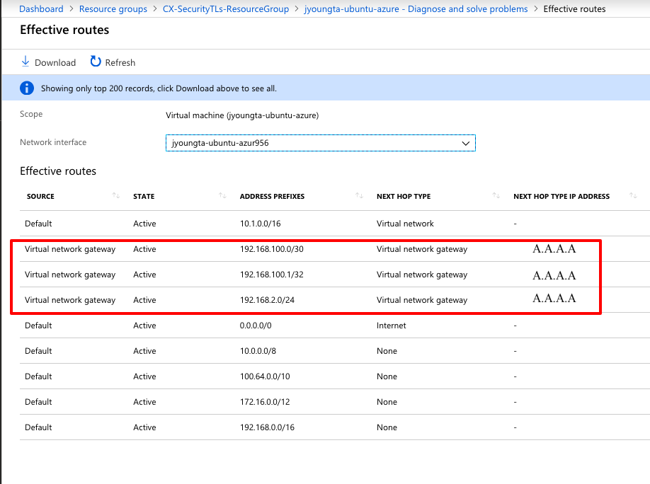
步骤6.立即查看远程VM上的有效路由。它们必须显示ASA向云通告的路由,如图所示。
故障排除
当前没有故障排除此配置的特定可用资料。
修订历史记录
| 版本 | 发布日期 | 备注 |
|---|---|---|
5.0 |
02-Jul-2026
|
更新的拼写、语法、CCW警报、句子结构和间距。 |
4.0 |
24-Sep-2024
|
更新的格式。 |
3.0 |
19-Mar-2024
|
更新的技术内容、机器翻译、可选文本和格式。 |
2.0 |
11-Jul-2022
|
此最新文章的内容仍然有效。
已删除PII。更新格式、样式要求、机器翻译和背景。 |
1.0 |
18-Feb-2019
|
初始版本 |
 反馈
反馈