Configure ASA IPsec VTI Connection to Azure
Available Languages
Introduction
This document describes how to configure an Adaptive Security Appliance (ASA) IPsec Virtual Tunnel Interface (VTI) connection to Azure.
Prerequisites
Requirements
Cisco recommends that you have knowledge of these topics:
- An ASA connected directly to the internet with a public static IPv4 address that runs ASA 9.8.1 or later
- An Azure account
Components Used
This document is not restricted to specific software and hardware versions.
The information in this document was created from the devices in a specific lab environment. All of the devices used in this document started with a cleared (default) configuration. If your network is live, ensure that you understand the potential impact of any command.
Background Information
In ASA 9.8.1, the IPsec VTI feature was extended to utilize IKEv2, however, it is still limited to sVTI IPv4 over IPv4. This configuration guide was produced with the use of the ASA CLI interface and the Azure Portal. The configuration of the Azure portal can also be performed with PowerShell or using an API. For more information on Azure configuration methods, refer to the Azure documentation.

Note: Currently, VTI is only supported in single-context, routed mode.
Configure
This guide assumes Azure Cloud has not been configured. Some of these steps can be skipped if the resources are already established.
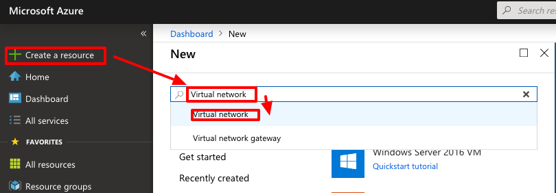
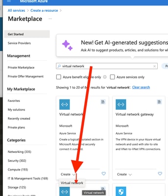
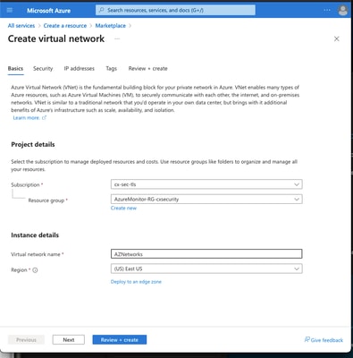
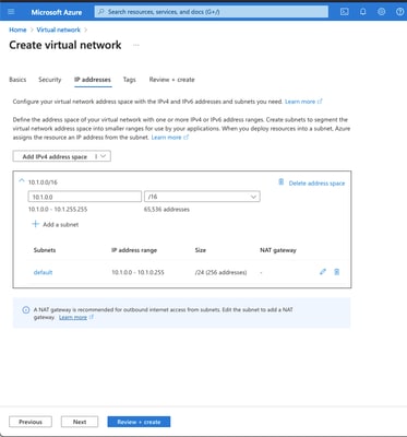
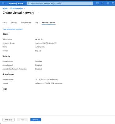
Step 1. Configure a Network within Azure
This is the network address space that lives in the Azure Cloud. This address space must be large enough to accommodate sub-networks within them, as shown in the image.
   |
|
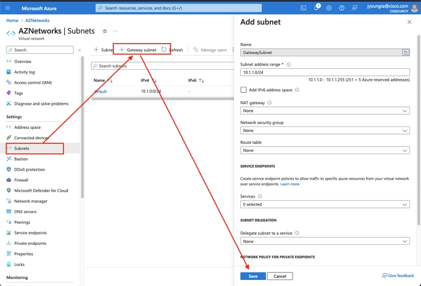
Step 2. Modify the Virtual Network to create a Gateway Subnet
1. Navigate to the Virtual network and add a Gateway subnet. In this example, 10.1.1.0/24 is used.
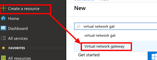
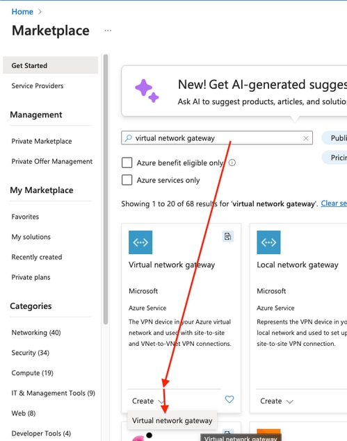
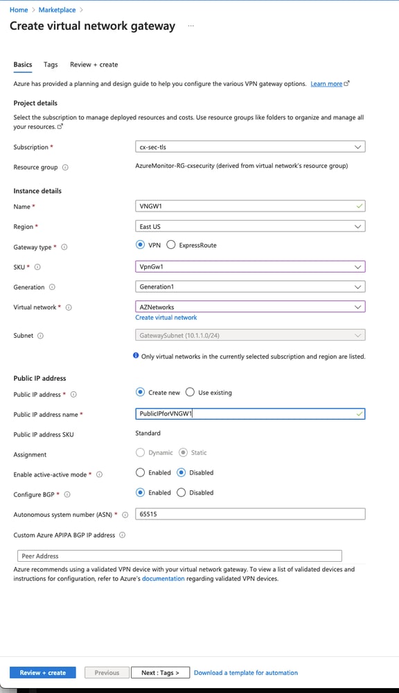
Step 3. Create a Virtual Network Gateway
1. This is the VPN endpoint that is hosted in the cloud. This is the device the ASA builds the IPsec tunnel with. This step also creates a public IP, which is assigned to the Virtual Network Gateway. This step can take 15 - 20 minutes to complete.
 |
|
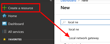
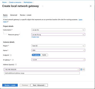
Step 4. Create a Local Network Gateway
1. A Local network gateway is the resource that represents the ASA.
  |
|
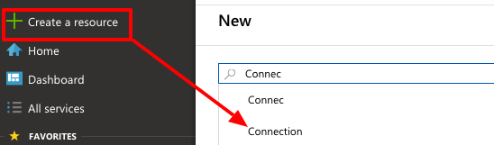
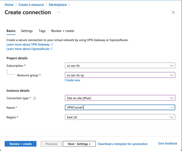
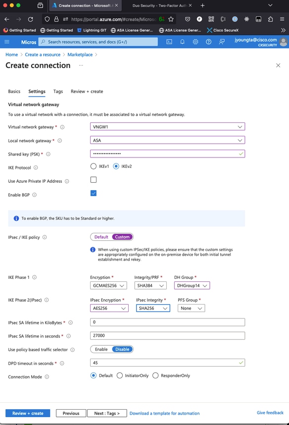
Step 5. Create a new connection between the Virtual Network Gateway and the Local Network Gateway, as shown in the image
Step 6. Configure the ASA
1. First, enable IKEv2 on the outside interface and configure the IKEv2 policies.
crypto ikev2 policy 10
 encryption aes-gcm-256 aes-gcm-192 aes-gcm
 integrity null
 group 14 5 2
 prf sha512 sha384 sha256 sha
 lifetime seconds 86400
crypto ikev2 policy 20
 encryption aes-256 aes-192 aes
 integrity sha512 sha384 sha256 sha
 group 14 5 2
 prf sha512 sha384 sha256 sha
 lifetime seconds 86400
crypto ikev2 enable outside
Step 6. Configure an IPsec transform set and an IPsec profile
crypto ipsec ikev2 ipsec-proposal AZURE-PROPOSAL
 protocol esp encryption aes-256
 protocol esp integrity sha-256
crypto ipsec profile AZURE-PROPOSAL
 set ikev2 ipsec-proposal AZURE-PROPOSAL
Step 7. Configure the tunnel-group.
1. Retrieve the Public IPv4 address of the Virtual Network Gateway created in Step 3, as shown in the image.
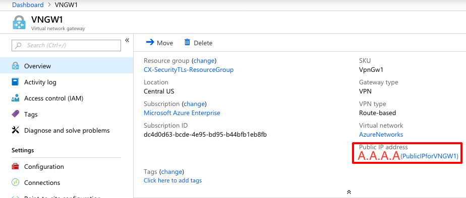
2. Then, configure on the ASA, a group-policy and tunnel-group with the pre-shared-key defined in Step 3.
group-policy AZURE internal
group-policy AZURE attributes
 vpn-tunnel-protocol ikev2
tunnel-group A.A.A.A type ipsec-l2l
tunnel-group A.A.A.A general-attributes
 default-group-policy AZURE
tunnel-group A.A.A.A ipsec-attributes
 ikev2 remote-authentication pre-shared-key *****
 ikev2 local-authentication pre-shared-key *****
Step 8. Configure the Tunnel Interface
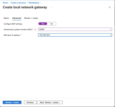
1. In Step 4, configure the Local Network Gateway, a network address and an IP address for the BGP connection that was configured. That is the IP address and network to configure on the VTI.
interface Tunnel1
 nameif AZURE
 ip address 192.168.100.1 255.255.255.252
 tunnel source interface outside
 tunnel destination A.A.A.A
 tunnel mode ipsec ipv4
 tunnel protection ipsec profile AZURE-PROPOSAL
 no shutdown
2. Option 1. Configure dynamic routing exchange routes with Azure with the use of BGP.
2a.. Locate the IP address of the BGP router in Azure to view the configuration of the virtual network gateway created in step 3. In this example, it is 10.1.2.254.
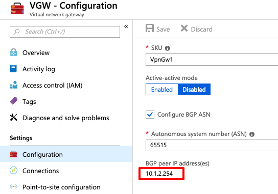
3. On the ASA, configure a static route that points to 10.1.2.254 out the VTI Tunnel. In this example, 192.168.100.2 is within the same subnet as the VTI. Although no device has that IP address, the ASA installs the route that points out the VTI interface.
route AZURE 10.1.2.254 255.255.255.255 192.168.100.2 1
4. Then, configure BGP on the ASA. The network 192.168.2.0/24 is the ASAs inside interface and a route that is propagated into the cloud. In addition, the networks configured in Azure are advertised to the ASA.
router bgp 65000
 bgp log-neighbor-changes
 bgp graceful-restart
 address-family ipv4 unicast
  neighbor 10.1.2.254 remote-as 65515
  neighbor 10.1.2.254 ebgp-multihop 255
  neighbor 10.1.2.254 activate
  network 192.168.2.0
  network 192.168.100.0 mask 255.255.255.252
  no auto-summary
  no synchronization
 exit-address-family
Option 2. Configure static routing, statically configure routes on both the ASA and Azure. Configure the ASA to send traffic to the Azure networks over the VTI tunnel.
route AZURE 10.1.0.0 255.255.0.0 192.168.100.2 1
1. Modify the Local Network Gateway created in Step 4 with networks that exist behind the ASA and the subnet on the tunnel interface. Then, add the prefixes under the Add Additional Network Spaces section.
Verify
Use this section to confirm your configuration works properly.
Step 1. Verify an IKEv2 session is established by running the show crypto ikev2 sa command.
ciscoasa# show crypto ikev2 sa

IKEv2 SAs:

Session-id:6, Status:UP-ACTIVE, IKE count:1, CHILD count:1

Tunnel-id Local                                               Remote                                                  Status         Role
2006974029 B.B.B.B.    /500                                   A.A.A.A/500                                             READY          INITIATOR
      Encr: AES-CBC, keysize: 256, Hash: SHA96, DH Grp:2, Auth sign: PSK, Auth verify: PSK
      Life/Active Time: 86400/4640 sec
Child sa: local selector  0.0.0.0/0 - 255.255.255.255/65535
          remote selector 0.0.0.0/0 - 255.255.255.255/65535
          ESP spi in/out: 0x74e90416/0xba17723a
Step 2. Verify an IPsec SA is also negotiated by running the show crypto ipsec sa command.
ciscoasa# show crypto ipsec sa
interface: AZURE
    Crypto map tag: __vti-crypto-map-3-0-1, seq num: 65280, local addr: B.B.B.B

      local ident (addr/mask/prot/port): (0.0.0.0/0.0.0.0/0/0)
      remote ident (addr/mask/prot/port): (0.0.0.0/0.0.0.0/0/0)
      current_peer: A.A.A.A


      #pkts encaps: 240, #pkts encrypt: 240, #pkts digest: 240
      #pkts decaps: 377, #pkts decrypt: 377, #pkts verify: 377
      #pkts compressed: 0, #pkts decompressed: 0
      #pkts not compressed: 240, #pkts comp failed: 0, #pkts decomp failed: 0
      #pre-frag successes: 0, #pre-frag failures: 0, #fragments created: 0
      #PMTUs sent: 0, #PMTUs rcvd: 0, #decapsulated frgs needing reassembly: 0
      #TFC rcvd: 0, #TFC sent: 0
      #Valid ICMP Errors rcvd: 0, #Invalid ICMP Errors rcvd: 0
      #send errors: 0, #recv errors: 0

      local crypto endpt.: B.B.B.B/500, remote crypto endpt.: A.A.A.A/500
      path mtu 1500, ipsec overhead 78(44), media mtu 1500
      PMTU time remaining (sec): 0, DF policy: copy-df
      ICMP error validation: disabled, TFC packets: disabled
      current outbound spi: BA17723A
      current inbound spi : 74E90416

    inbound esp sas:
      spi: 0x74E90416 (1961427990)
         SA State: active
         transform: esp-aes-256 esp-sha-256-hmac no compression
         in use settings ={L2L, Tunnel, IKEv2, VTI, }
         slot: 0, conn_id: 1722, crypto-map: __vti-crypto-map-3-0-1
         sa timing: remaining key lifetime (kB/sec): (3962863/24100)
         IV size: 16 bytes
         replay detection support: Y
         Anti replay bitmap:
          0xFFFFFFFF 0xFFFFFFFF
    outbound esp sas:
      spi: 0xBA17723A (3122098746)
         SA State: active
         transform: esp-aes-256 esp-sha-256-hmac no compression
         in use settings ={L2L, Tunnel, IKEv2, VTI, }
         slot: 0, conn_id: 1722, crypto-map: __vti-crypto-map-3-0-1
         sa timing: remaining key lifetime (kB/sec): (4008947/24100)
         IV size: 16 bytes
         replay detection support: Y
         Anti replay bitmap:
          0x00000000 0x00000001

ciscoasa#
Step 3. Verify connectivity over the tunnel to the BGP remote router by running the ping and ping tcp command to validate layer 3 routing and layer 4 connectivity for BGP or the endpoint resources if you use static routing.
ciscoasa# ping 10.1.2.254
Type escape sequence to abort.
Sending 5, 100-byte ICMP Echos to 10.1.2.254, timeout is 2 seconds:
!!!!!
Success rate is 100 percent (5/5), round-trip min/avg/max = 40/42/50 ms
ciscoasa# ping tcp 10.1.2.254 179
Type escape sequence to abort.
No source specified. Pinging from identity interface.
Sending 5 TCP SYN requests to 10.1.2.254 port 179
from 192.168.100.1, timeout is 2 seconds:
!!!!!
Success rate is 100 percent (5/5), round-trip min/avg/max = 41/42/42 ms
ciscoasa#
Step 4. When you use BGP, verify BGP connectivity routes are received and advertised to Azure and the routing table of the ASA.
ciscoasa# show bgp summary
BGP router identifier 192.168.100.1, local AS number 65000
BGP table version is 6, main routing table version 6
4 network entries using 800 bytes of memory
5 path entries using 400 bytes of memory
2/2 BGP path/bestpath attribute entries using 416 bytes of memory
1 BGP AS-PATH entries using 24 bytes of memory
0 BGP route-map cache entries using 0 bytes of memory
0 BGP filter-list cache entries using 0 bytes of memory
BGP using 1640 total bytes of memory
BGP activity 14/10 prefixes, 17/12 paths, scan interval 60 secs

Neighbor        V           AS MsgRcvd MsgSent   TblVer  InQ OutQ Up/Down  State/PfxRcd
10.1.2.254      4        65515 73      60             6    0    0 01:02:26  3

ciscoasa# show bgp neighbors 10.1.2.254 routes

BGP table version is 6, local router ID is 192.168.100.1
Status codes: s suppressed, d damped, h history, * valid, > best, i - internal,
              r RIB-failure, S Stale, m multipath
Origin codes: i - IGP, e - EGP, ? - incomplete

   Network          Next Hop        Metric LocPrf Weight  Path
*> 10.1.0.0/16      10.1.2.254                         0  65515 i   <<< This is the virtual network defined in Azure
*  192.168.100.0/30 10.1.2.254                         0  65515 i
r> 192.168.100.1/32 10.1.2.254                         0  65515 i

Total number of prefixes 3
ciscoasa# show bgp neighbors 10.1.2.254 advertised-routes

BGP table version is 6, local router ID is 192.168.100.1
Status codes: s suppressed, d damped, h history, * valid, > best, i - internal,
              r RIB-failure, S Stale, m multipath
Origin codes: i - IGP, e - EGP, ? - incomplete

   Network          Next Hop        Metric LocPrf Weight  Path
*> 192.168.2.0      0.0.0.0              0         32768  i        <<< These are the routes being advertised to Azure
*> 192.168.100.0/30 0.0.0.0              0         32768  i        <<<

Total number of prefixes 2
ciscoasa#
ciscoasa# show route

Codes: L - local, C - connected, S - static, R - RIP, M - mobile, B - BGP
       D - EIGRP, EX - EIGRP external, O - OSPF, IA - OSPF inter area
       N1 - OSPF NSSA external type 1, N2 - OSPF NSSA external type 2
       E1 - OSPF external type 1, E2 - OSPF external type 2, V - VPN
       i - IS-IS, su - IS-IS summary, L1 - IS-IS level-1, L2 - IS-IS level-2
       ia - IS-IS inter area, * - candidate default, U - per-user static route
       o - ODR, P - periodic downloaded static route, + - replicated route
Gateway of last resort is 10.1.251.33 to network 0.0.0.0

S*       0.0.0.0 0.0.0.0 [1/0] via B.B.B.C, outside
B        10.1.0.0 255.255.0.0 [20/0] via 10.1.1.254, 01:03:33
S        10.1.2.254 255.255.255.255 [1/0] via 192.168.100.2, AZURE
C        B.B.B.A 255.255.255.224 is directly connected, outside
L        B.B.B.B 255.255.255.255 is directly connected, outside
C        192.168.2.0 255.255.255.0 is directly connected, inside
L        192.168.2.2 255.255.255.255 is directly connected, inside
C        192.168.100.0 255.255.255.252 is directly connected, AZURE
L        192.168.100.1 255.255.255.255 is directly connected, AZURE
Step 5. Ping a device over the tunnel. In this example, it is an Ubuntu VM that runs in Azure.
ciscoasa# ping 10.1.0.4
Type escape sequence to abort.
Sending 5, 100-byte ICMP Echos to 10.1.0.4, timeout is 2 seconds:
!!!!!
Success rate is 100 percent (5/5), round-trip min/avg/max = 40/42/50 ms
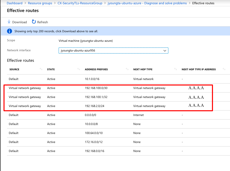
Step 6. View the effective routes on the remote VM now. They must show the routes the ASA advertised to the cloud, as shown in the image.
Troubleshoot
There is currently no specific information available to troubleshoot this configuration.
Revision History
| Revision | Publish Date | Comments |
|---|---|---|
5.0 |
02-Jul-2026
|
Updated spelling, grammar, CCW alerts, sentence structure, and spacing. |
4.0 |
24-Sep-2024
|
Updated Formatting. |
3.0 |
19-Mar-2024
|
Updated Tech Content, Machine Translation, Alt Text and Formatting. |
2.0 |
11-Jul-2022
|
Content for this recert article is still valid.
Removed PII.
Updates made to formatting, style requirements, machine tranlslation, and gerunds. |
1.0 |
18-Feb-2019
|
Initial Release |
 Feedback
Contact Cisco
- Open a Support Case

- (Requires a Cisco Service Contract)