简介 本文档介绍以应用 为中心的基础设施(ACI)中的带内(INB)管理配置。
先决条件 要求 Cisco 建议您了解以下主题:
*了解ACI访问策略
在ACI中配置INB之前,需要完成交换矩阵发现。
使用的组件 本文档中的信息基于以下软件和硬件版本:
应用策略基础设施控制器 (APIC) 浏览器
运行5.2(8e)的ACI
本文档中的信息都是基于特定实验室环境中的设备编写的。本文档中使用的所有设备最初均采用原始(默认)配置。如果您的网络处于活动状态,请确保您了解所有命令的潜在影响。
配置 配置分为三个主要步骤:
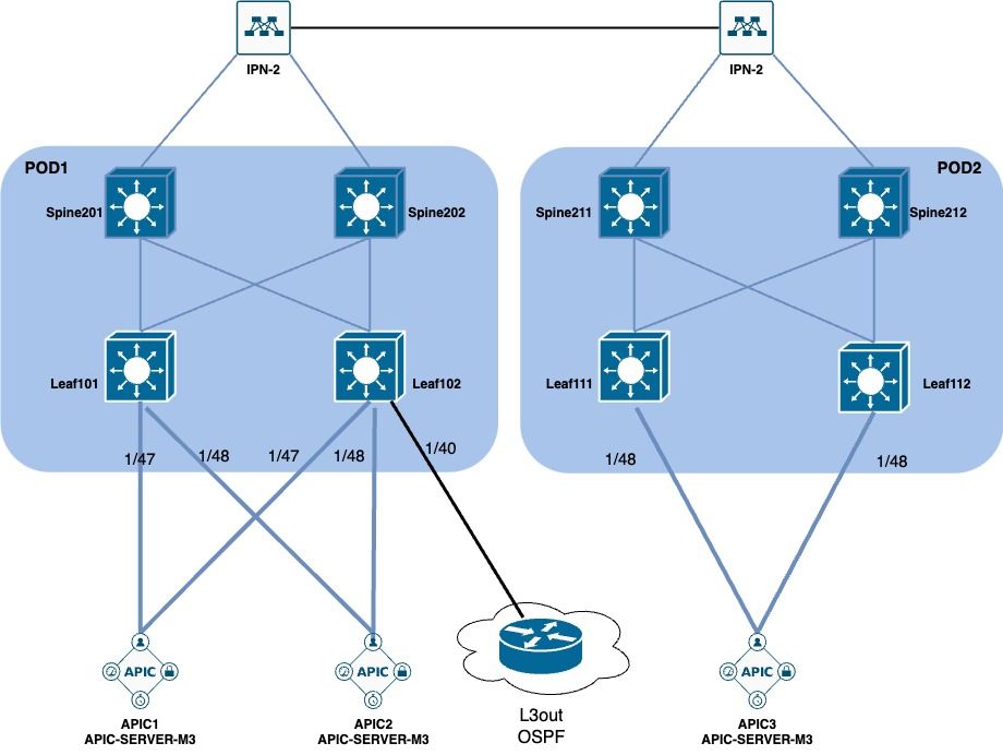
网络图
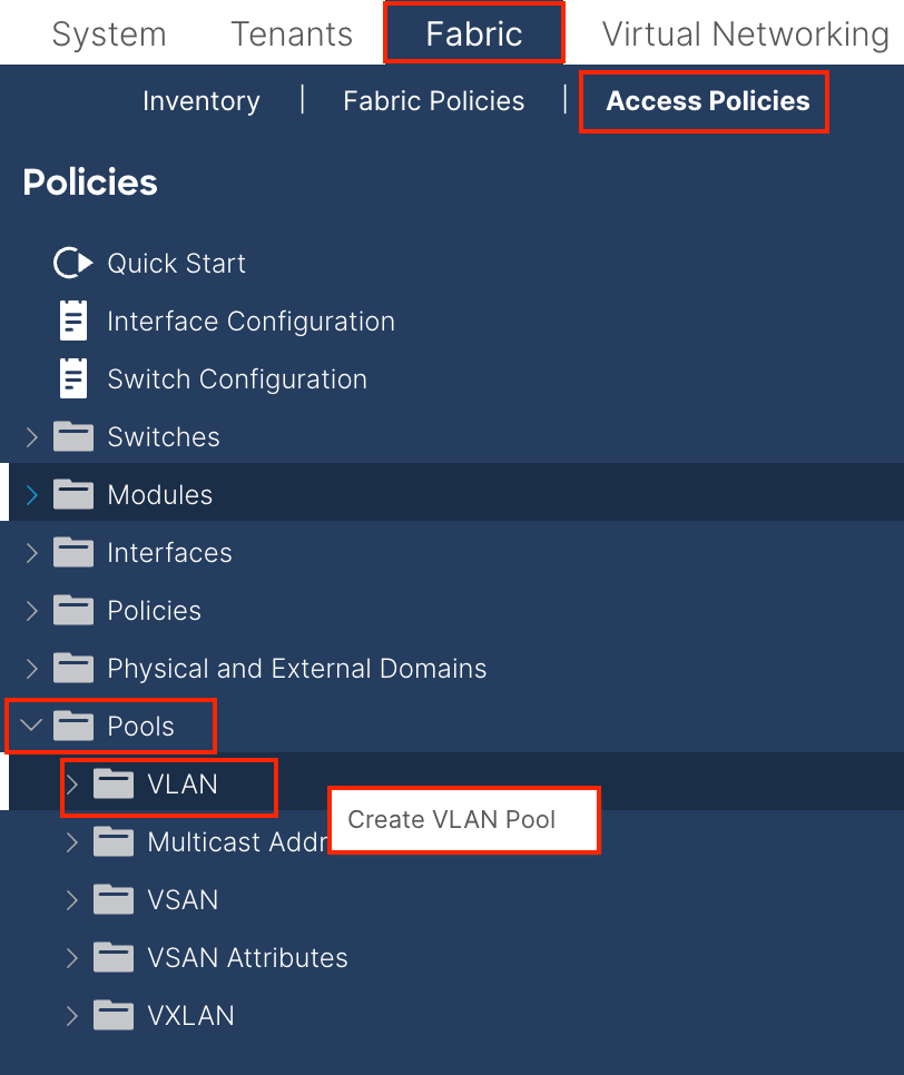
1.在枝叶接口中配置INB的VLAN 1.1.创建VLAN池 导航至APIC Web GUI路径;Fabric > Access Policies > Pools > VLAN
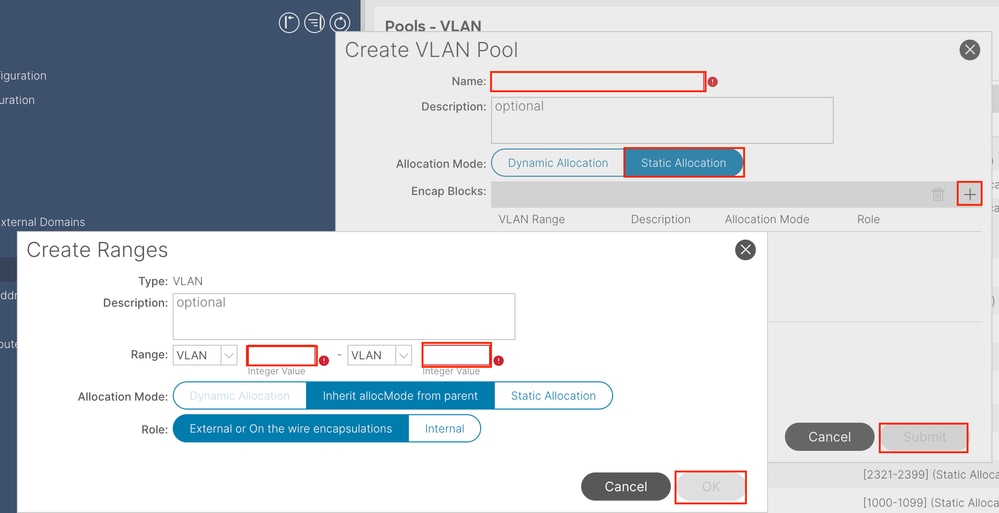
名称- VLAN池的名称。 此名称可以是1到64个字母数字字符。
说明- VLAN池的说明。 说明可以是0到128个字母数字字符。
分配模式 — 此VLAN池的分配方法对于INB必须是静态的。
Encap Blocks — 已分配VLAN池的范围。
范围 — VLAN池的开始VLAN ID和结束VLAN ID。起始ID必须小于或等于结束ID。
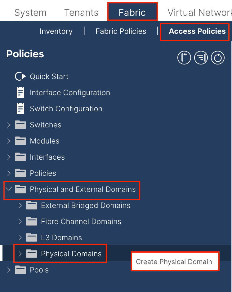
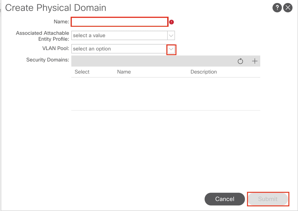
1.2.创建物理域 导航至APIC Web GUI路径;Fabric > Access Policies > Physical and External Domains > Physical Domains
名称 — 物理域的名称。 此名称可以是1到64个字母数字字符。
VLAN Pool — 选择第1 .1步中创建的VLAN Pool。
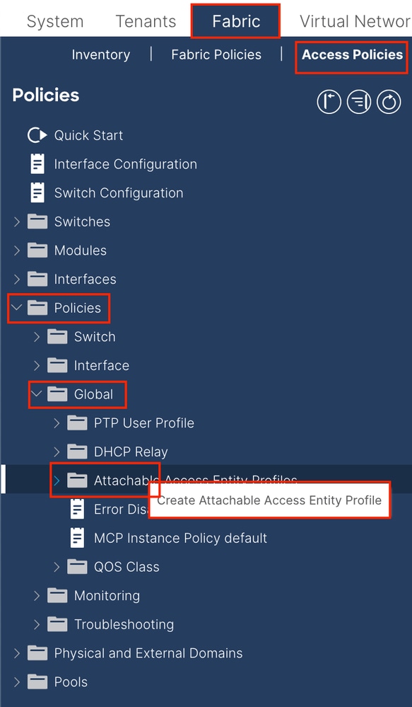
1.3.创建可附加访问实体配置文件 导航至APIC Web GUI路径;Fabric > Access Policies > Policies > Global > Attachable Access Entity Profile
Name — 可附加访问标识配置文件的名称。 此名称可以是1到64个字母数字字符。
Association to Interfaces — 取消选中。在最后一步中,在第1.6步中手动分配到枝叶的接口。
要与接口关联的域(VMM、物理或外部) — 选择在步骤1.2中创建的物理域。
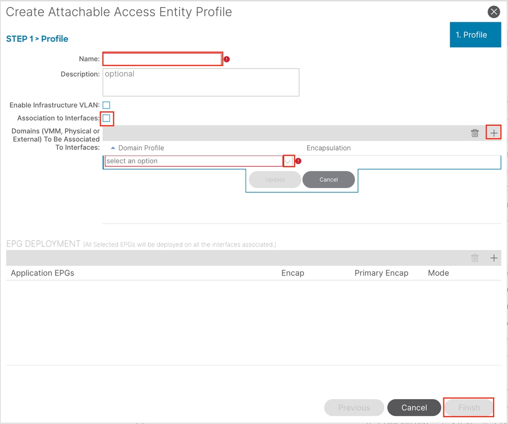
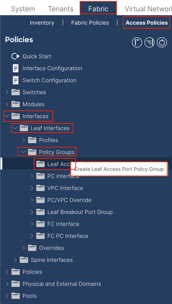
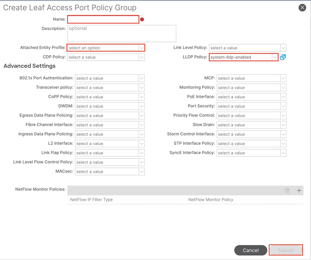
1.4.创建枝叶接入端口策略组 导航至APIC Web GUI路径;Fabric > Access Policies > Interfaces > Leaf Interfaces > Policy Groups > Leaf Access Port Policy Group
名称 — 枝叶接入端口策略组的名称。此名称可以是1到64个字母数字字符。
附加实体配置文件 — 选择在步骤1.3中创建的附加实体配置文件 。
链路层发现协议(LLDP)策略 — 必须选择启用策略 。
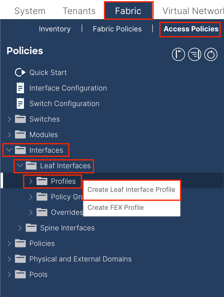
1.5.创建枝叶接口配置文件 导航至APIC Web GUI路径;Fabric > Access Policies > Interfaces > Leaf Interfaces > Profiles
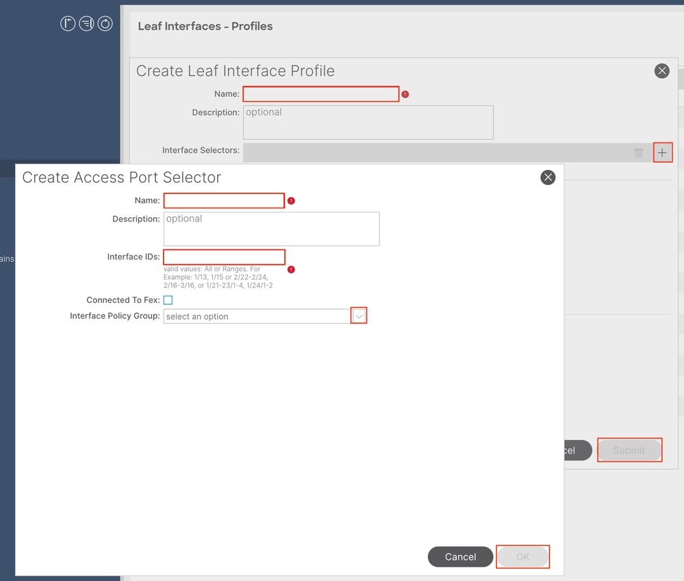
名称 — 枝叶接口配置文件的名称。此名称可以是1到64个字母数字字符。
接口选择器 — 在接口和接口策略之间 创建对应关系。
名称 — 接入端口选择器的名称。此名称可以是1到64个字母数字字符。
接口ID — 接口ID与APIC互连。在文档拓扑中,此接口ID为1/47或1/48。
Interface Policy Group — 选择Attached Entity Profile 在步骤1.4中创建。
注意: 在本文档的拓扑中,将三个APIC连接到枝叶的接口不同。
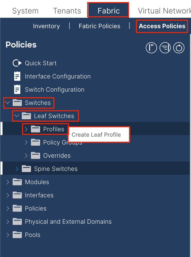
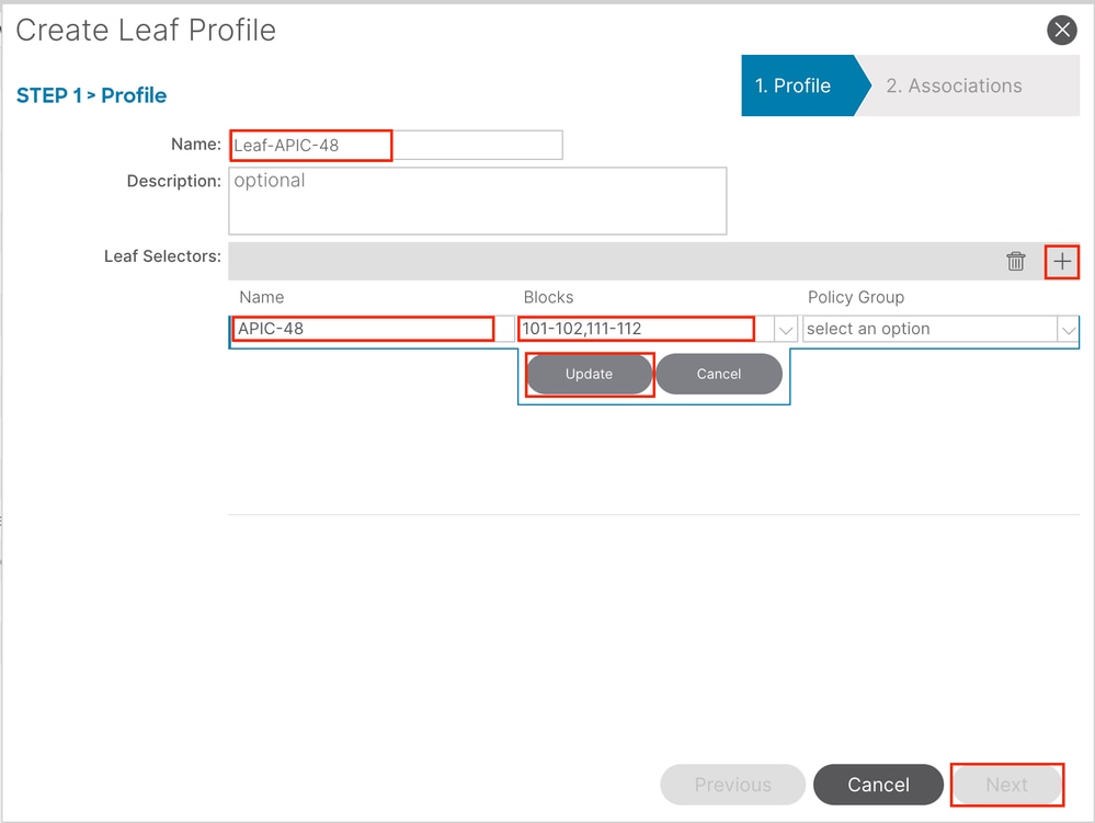
1.6.将接口配置文件应用到枝叶 导航至APIC Web GUI路径;Fabric > Access Policies > Switches > Leaf Switches > Profiles
名称 — 枝叶配置文件的名称。此名称可以是1到64个字母数字字符。
枝叶选择器 — 选择将接口配 置推送到其中的枝叶ID。
名称 — 枝叶组的名称。
块 — 选择交换机 节点ID 。
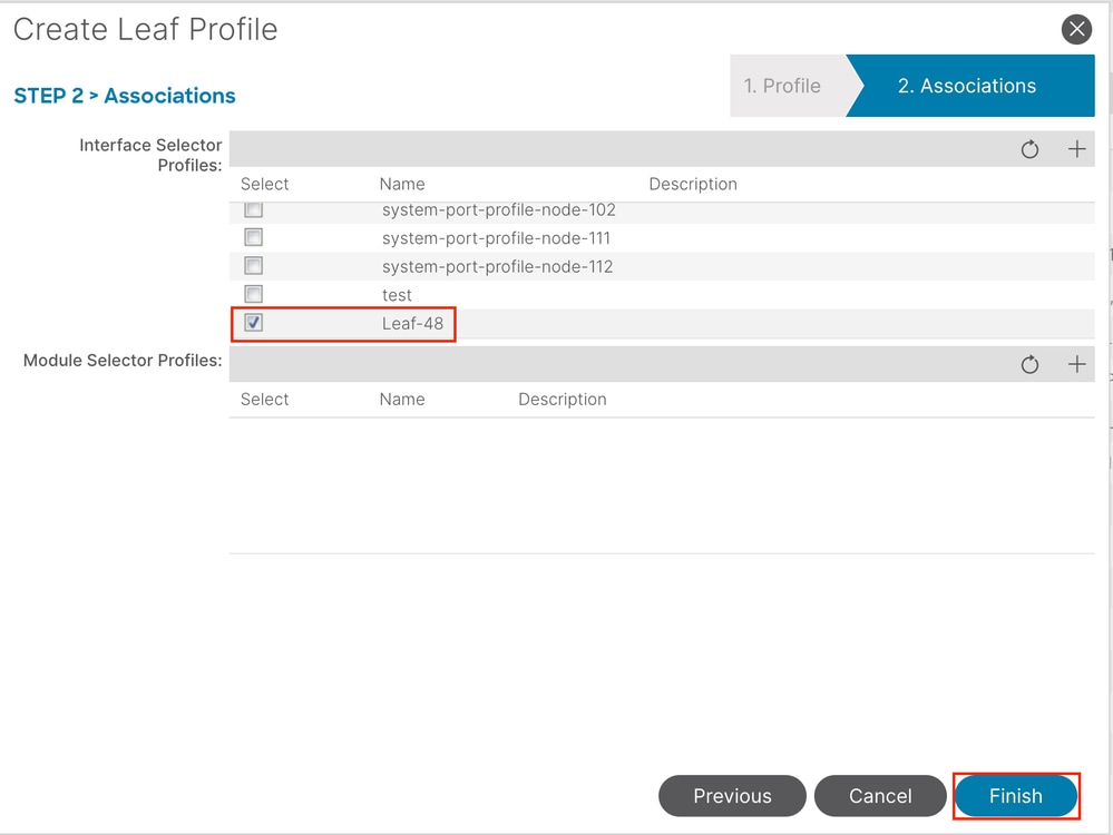
Interface Selector Profiles — 选择在步骤1.5中创建的Attached Entity Profile。
注意: 在本文档示例中,必须配置两个交换机配置文件。
有关访问策略的更多故障排除详细信息,请参阅ACI访问策略故障排除 。
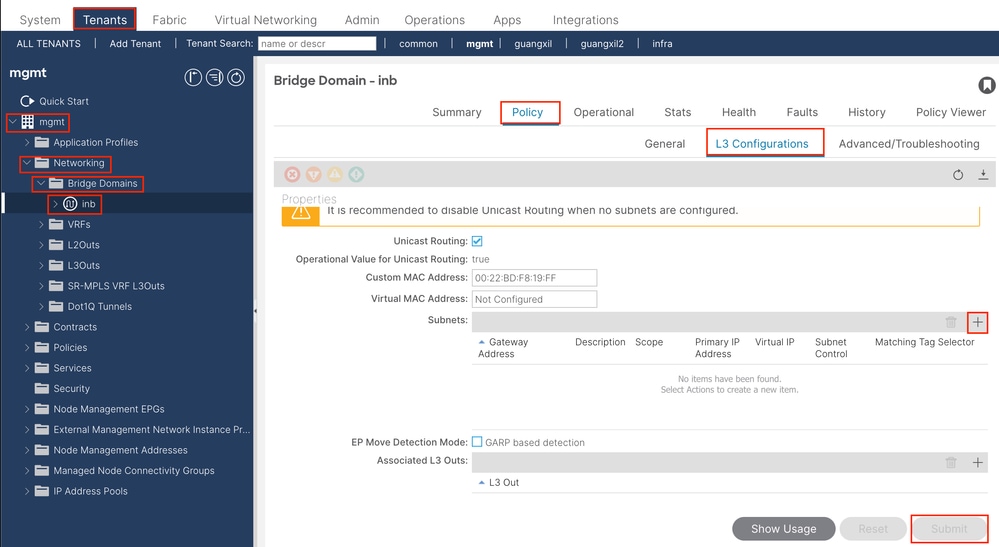
2.在管理租户中分配INB地址 2.1.创建网桥域(BD)INB子网 导航至APIC Web GUI路径;Tenants > mgmt > Networking > Bridge Domains > inb
注意: 本文档使用默认BD和默认VRF。
您还可以创建新的VRF和BD以执行类似的配置。
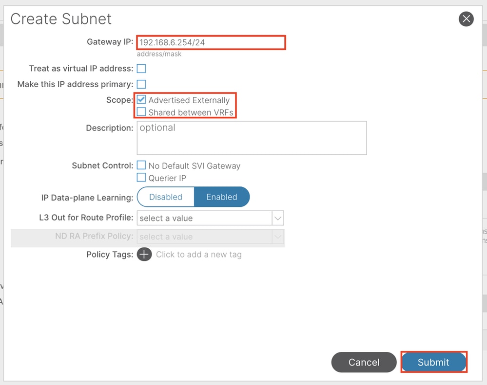
Gateway IP - The INB subnet gateway.
Scope - Choose according to the route leakage method you used. Here, choose to use L3out , and then click Advertised Externally .
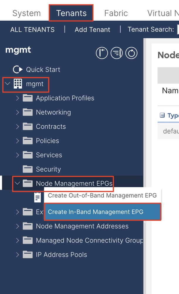
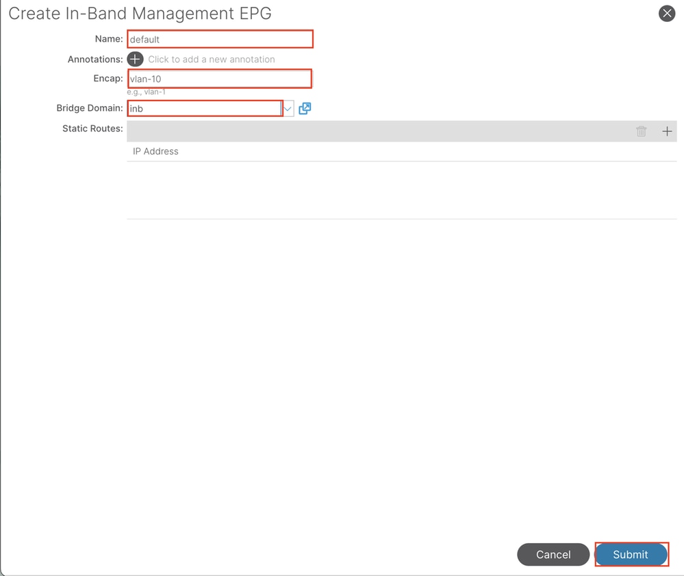
2.2.创建INB EPG 导航至APIC Web GUI路径;Tenants > mgmt > Node Management EPGs
Name - INB EPG的名称。
Encap — 在VLAN池中选择VLAN ,如您在步骤1.1中所创建。
网桥域 — 选择在步骤2.1中创建的BD。
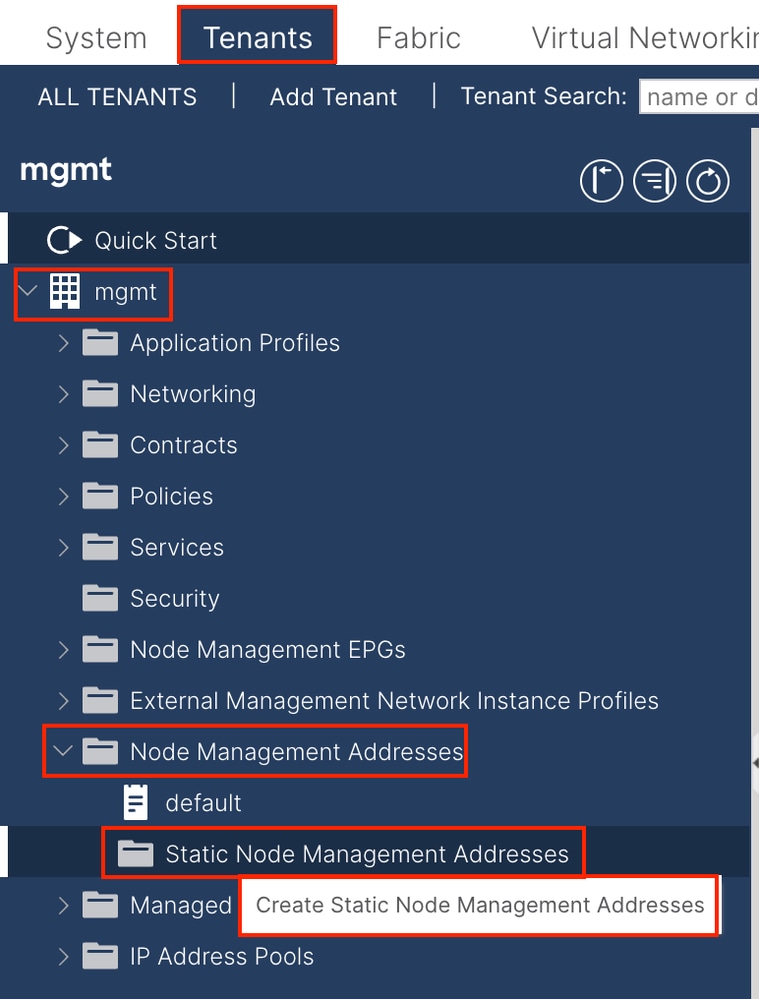
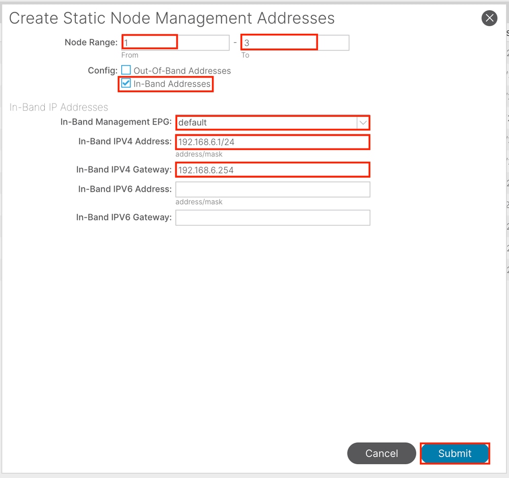
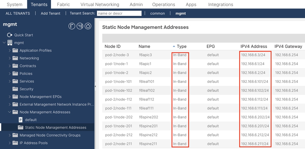
2.3.为设备分配静态INB IP地址 导航至APIC Web GUI路径;Tenants > mgmt > Node Management Addresses > Static Node Management Addresses
节点范围 — 要分配给INB地址的节点ID。分配的INB地址随节点ID按顺序增加。
Configuration — 选择带内地址 。
带内管理EPG — 选择步骤2.2中创建的EPG 。
带内IPV4地址 — 第一个分配的INB地址。
带内IPV4网关 — 将其配置为第2.1步中添加的子网的地址。
注意: 完成步骤2.3中的配置后,所有枝叶和APIC均可通过INB通信。
3.泄漏INB地址 您可以通过任何路由泄漏方法将INB子网共享给其他网络。INB EPG可以视为一个特殊的EPG。配置路由泄漏时,正常EPG没有区别。
本文档仅将L3out配置为示例。
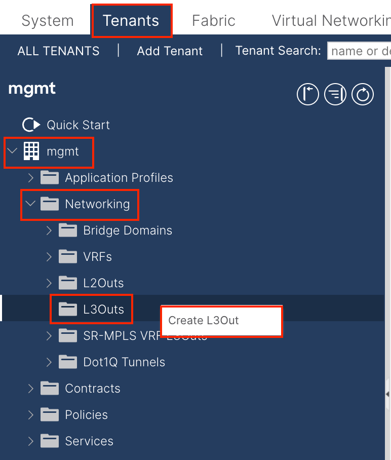
3.1.在管理租户中创建L3out
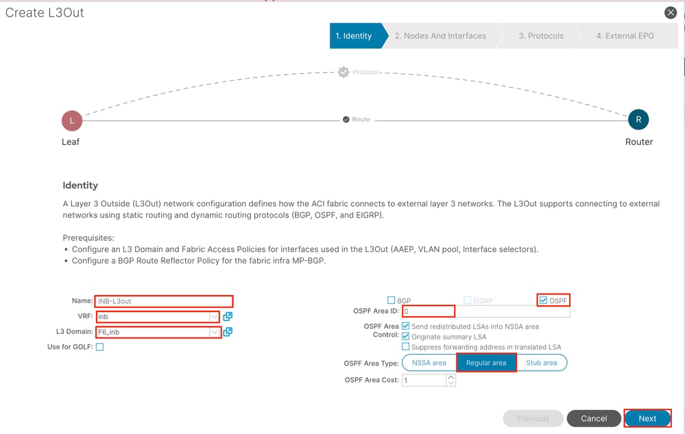
在本示例中,物理接口用于运行简单开放最短路径优先(OSPF)协议的路由器。
Name - INB L3out的名称。
VRF — 选择L3out路由所在的VRF 。在本文档中,使用最简单的配置,并选择管理租户中的VRF INB。
L3域 — 根据实际情况创建和选择。有关L3域的详细信息,请参阅L3out白皮书。
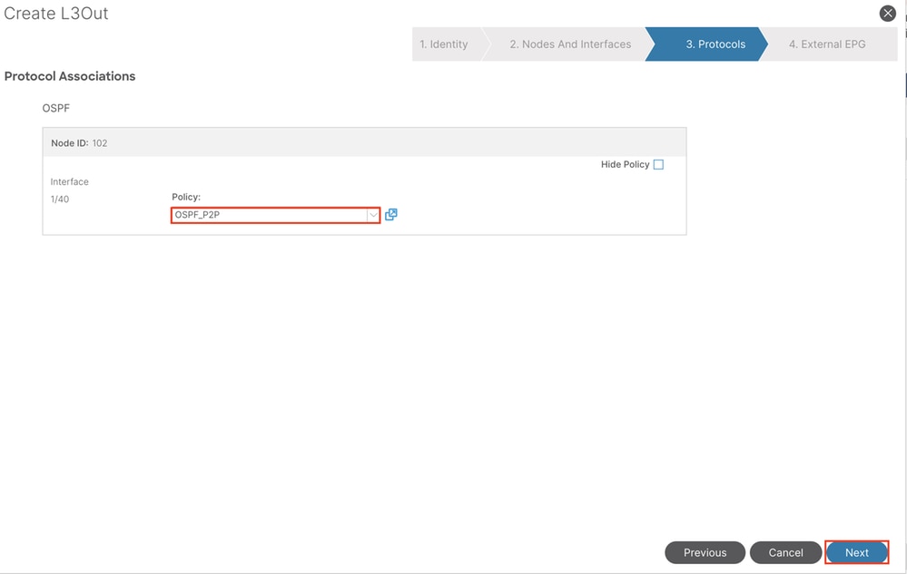
OSPF — 在本示例中,L3out运行OSPF协议。根据实际情况选择动态 路由协议或使用静态 路由。
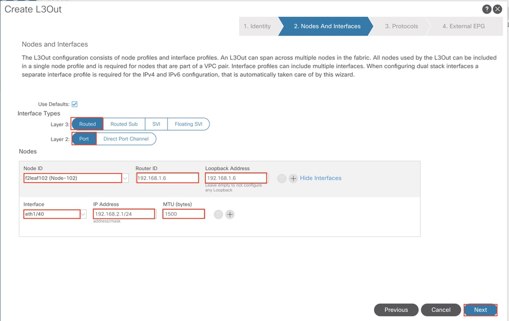
根据网络计划配置接口。
对于OSPF,默认网络类型为broadcast。此示例将网络类型更改为点对点。
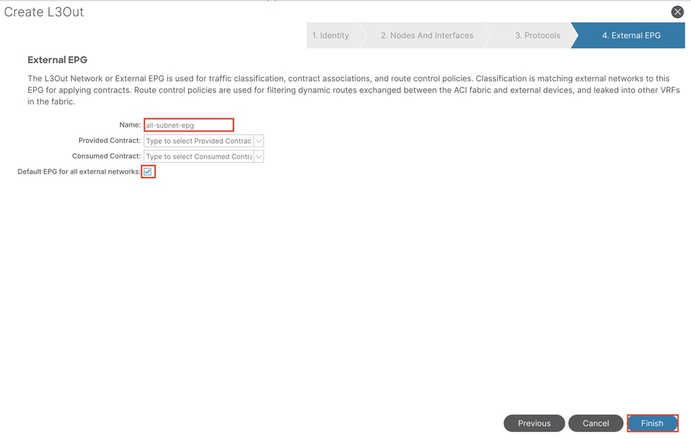
在本示例中,只有一个L3out和一个EPG,并且可以使用所有外部网络的默认EPG选项。
注意: 如果同一VRF中有多个L3out EPG,请仔细配置此选项。有关详细信息,请参阅L3out白皮书。
配置路由器后,OSPF邻居状态可以更改为FULL。
admin-Infra# show lldp neighbors
Capability codes:
  (R) Router, (B) Bridge, (T) Telephone, (C) DOCSIS Cable Device
  (W) WLAN Access Point, (P) Repeater, (S) Station, (O) Other
Device ID            Local Intf      Hold-time  Capability  Port ID
f6leaf102.aci.pub    Eth4/37         120        BR           Eth1/40
admin-Infra# show run

version 8.2(6)

feature ospf
interface loopback66
  vrf member aci-inb
  ip address 192.168.1.7/32
  ip router ospf aci-inb area 0.0.0.0
interface Ethernet4/37
  vrf member aci-inb
  ip address 192.168.2.2/24
  ip ospf network point-to-point
  ip router ospf aci-inb area 0.0.0.0
  no shutdown
vrf context aci-inb
  address-family ipv4 unicast
router ospf aci-inb
  vrf aci-inb
    router-id 192.168.1.7

admin-Infra# show ip ospf neighbors vrf aci-inb
 OSPF Process ID aci-inb VRF aci-inb
 Total number of neighbors: 1
 Neighbor ID     Pri State            Up Time  Address         Interface
 192.168.1.6       1 FULL/ -          00:04:01 192.168.2.1     Eth4/37
admin-Infra#

f6leaf102# show ip int bri vrf mgmt:inb
IP Interface Status for VRF "mgmt:inb"(27)
Interface            Address              Interface Status
eth1/40              192.168.2.1/24       protocol-up/link-up/admin-up
vlan7                192.168.6.254/24     protocol-up/link-up/admin-up
lo37                 192.168.1.6/32       protocol-up/link-up/admin-up
f6leaf102# show ip ospf neighbors vrf mgmt:inb
 OSPF Process ID default VRF mgmt:inb
 Total number of neighbors: 1
 Neighbor ID     Pri State            Up Time  Address         Interface
 192.168.1.7       1 FULL/ -          00:05:08 192.168.2.2     Eth1/40
f6leaf102# 如果您需要在L3out中进行故障排除,请参阅ACI外部转发故障排除 。
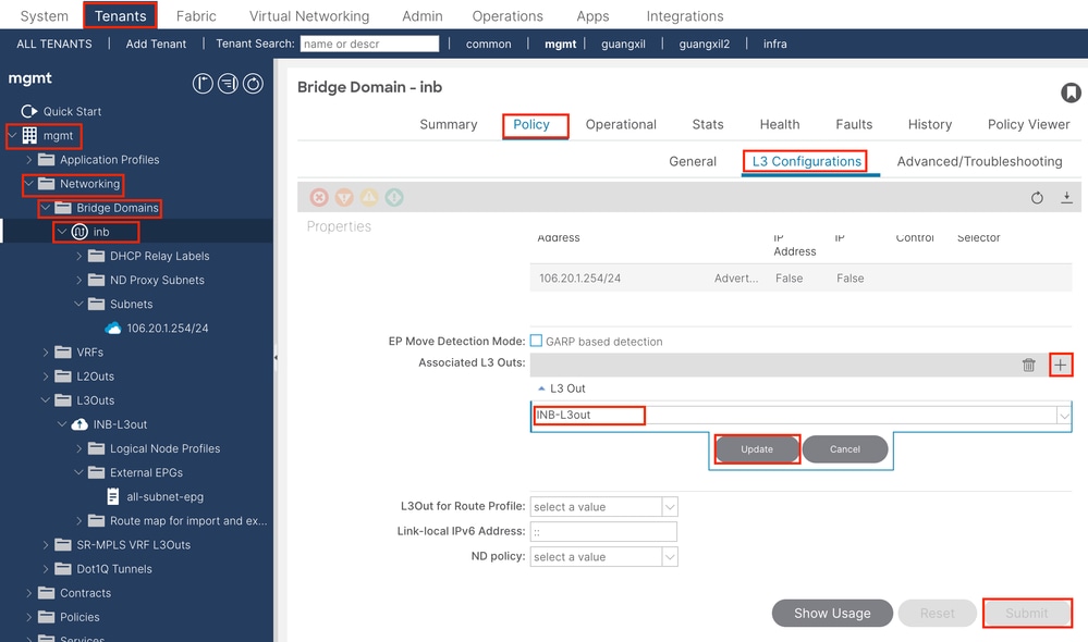
3.2.与L3out关联的BD 导航至APIC Web GUI路径;Tenants > mgmt > Networking > Bridge Domains > inb
关联的L3out — 选择在步骤3.1中创建的 管理L3out的名称。
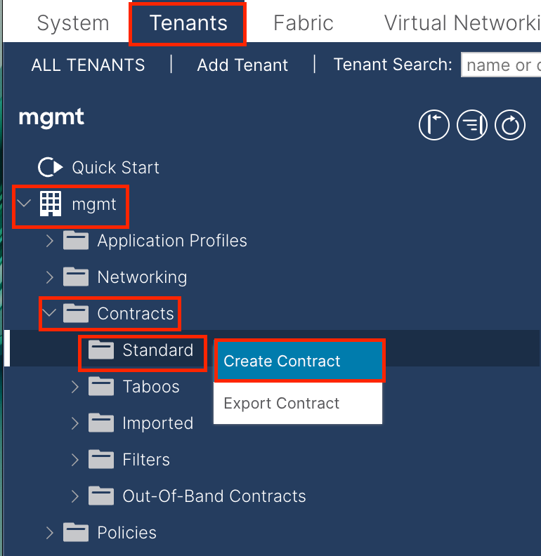
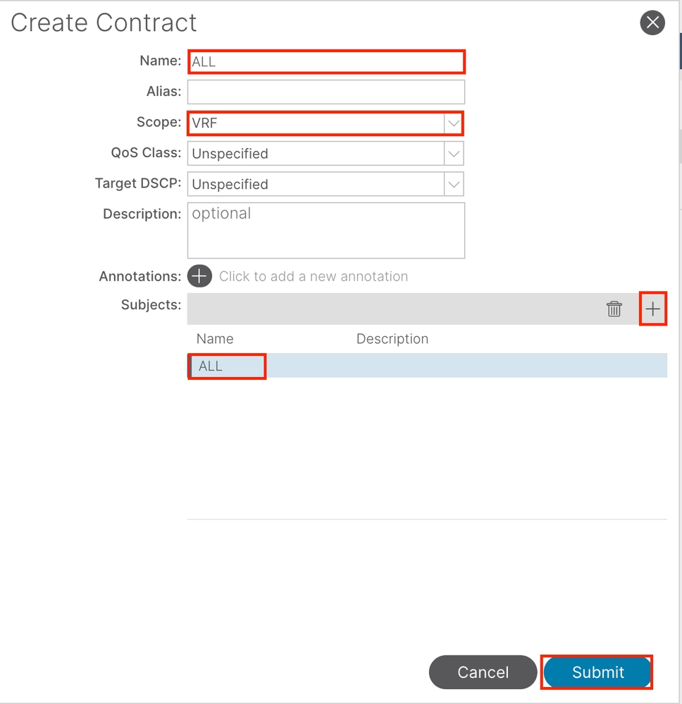
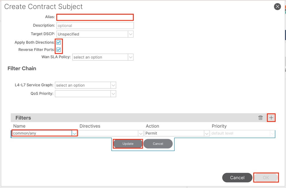
3.3.创建合同 导航至APIC Web GUI路径;Tenants > mgmt > Contracts > Standard
在本示例中,合同允许所有流量。如果您需要有关合同的更多详细信息,请参阅合同白皮书;思科ACI合同指南白皮书 。
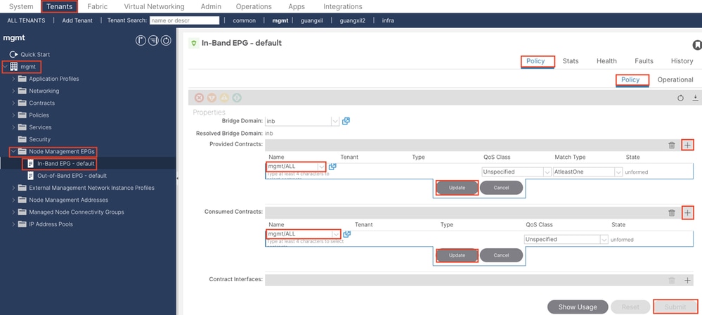
3.4.将合同应用于INB EPG 导航至APIC Web GUI路径;Tenants > mgmt > Node Management EPGs > In-Band EPG - default
提供的合同 — 选择第3.3步中创建的合同 。
已使用合同 — 选择第3.3步中创建的合同 。
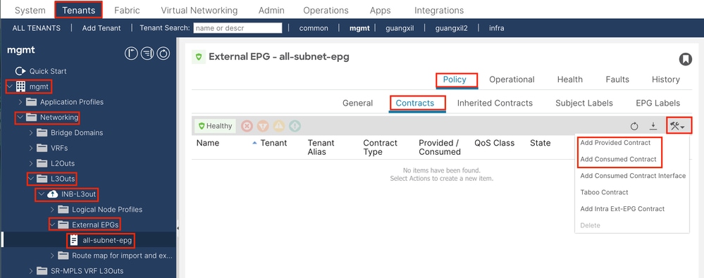
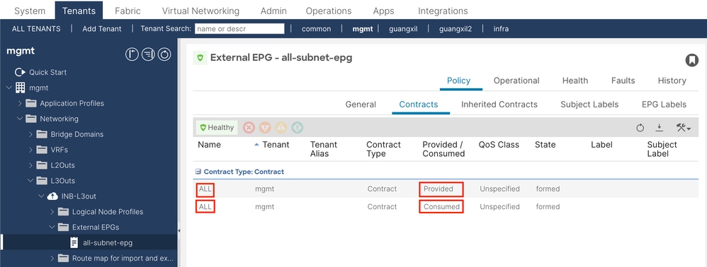
3.5.将合同应用于L3out EPG 导航至APIC Web GUI路径;Tenants > mgmt > Networking > L3Outs > INB-L3out > External EPGs > all-subnet-epg
添加提供的合同 — 在步骤3.3中创建的合同。
添加使用的合同 — 在步骤3.3中创建的合同。
应用该合同后,您可以在已提供和已使用的合同中看到该合同。
验证 您可以在外部路由器中看到INB路由。
admin-Infra# show ip route vrf aci-inb
IP Route Table for VRF "aci-inb"
'*' denotes best ucast next-hop
'**' denotes best mcast next-hop
'[x/y]' denotes [preference/metric]
'%' in via output denotes VRF

192.168.1.6/32, ubest/mbest: 1/0
    *via 192.168.2.1, Eth4/37, [110/5], 00:37:40, ospf-aci-inb, intra
192.168.1.7/32, ubest/mbest: 2/0, attached
    *via 192.168.1.7, Lo66, [0/0], 00:04:06, local
    *via 192.168.1.7, Lo66, [0/0], 00:04:06, direct
192.168.2.0/24, ubest/mbest: 1/0, attached
    *via 192.168.2.2, Eth4/37, [0/0], 00:37:51, direct
192.168.2.2/32, ubest/mbest: 1/0, attached
    *via 192.168.2.2, Eth4/37, [0/0], 00:37:51, local
192.168.6.0/24, ubest/mbest: 1/0
    *via 192.168.2.1, Eth4/37, [110/20], 00:24:38, ospf-aci-inb, type-2
admin-Infra#
admin-Infra# ping 192.168.6.1 vrf aci-inb
PING 192.168.6.1 (192.168.6.1): 56 data bytes
64 bytes from 192.168.6.1: icmp_seq=0 ttl=62 time=0.608 ms
64 bytes from 192.168.6.1: icmp_seq=1 ttl=62 time=0.55 ms
64 bytes from 192.168.6.1: icmp_seq=2 ttl=62 time=0.452 ms
64 bytes from 192.168.6.1: icmp_seq=3 ttl=62 time=0.495 ms
64 bytes from 192.168.6.1: icmp_seq=4 ttl=62 time=0.468 ms

--- 192.168.6.1 ping statistics ---
5 packets transmitted, 5 packets received, 0.00% packet loss
round-trip min/avg/max = 0.452/0.514/0.608 ms
admin-Infra# ping 192.168.6.3 vrf aci-inb
PING 192.168.6.3 (192.168.6.3): 56 data bytes
64 bytes from 192.168.6.3: icmp_seq=0 ttl=61 time=0.731 ms
64 bytes from 192.168.6.3: icmp_seq=1 ttl=61 time=0.5 ms
64 bytes from 192.168.6.3: icmp_seq=2 ttl=61 time=0.489 ms
64 bytes from 192.168.6.3: icmp_seq=3 ttl=61 time=0.508 ms
64 bytes from 192.168.6.3: icmp_seq=4 ttl=61 time=0.485 ms

--- 192.168.6.3 ping statistics ---
5 packets transmitted, 5 packets received, 0.00% packet loss
round-trip min/avg/max = 0.485/0.542/0.731 ms
admin-Infra# ping 192.168.6.201 vrf aci-inb
PING 192.168.6.201 (192.168.6.201): 56 data bytes
64 bytes from 192.168.6.201: icmp_seq=0 ttl=63 time=0.765 ms
64 bytes from 192.168.6.201: icmp_seq=1 ttl=63 time=0.507 ms
64 bytes from 192.168.6.201: icmp_seq=2 ttl=63 time=0.458 ms
64 bytes from 192.168.6.201: icmp_seq=3 ttl=63 time=0.457 ms
64 bytes from 192.168.6.201: icmp_seq=4 ttl=63 time=0.469 ms

--- 192.168.6.201 ping statistics ---
5 packets transmitted, 5 packets received, 0.00% packet loss
round-trip min/avg/max = 0.457/0.531/0.765 ms
admin-Infra# ping 192.168.6.211 vrf aci-inb
PING 192.168.6.211 (192.168.6.211): 56 data bytes
64 bytes from 192.168.6.211: icmp_seq=0 ttl=63 time=0.814 ms
64 bytes from 192.168.6.211: icmp_seq=1 ttl=63 time=0.525 ms
64 bytes from 192.168.6.211: icmp_seq=2 ttl=63 time=0.533 ms
64 bytes from 192.168.6.211: icmp_seq=3 ttl=63 time=0.502 ms
64 bytes from 192.168.6.211: icmp_seq=4 ttl=63 time=0.492 ms

--- 192.168.6.211 ping statistics ---
5 packets transmitted, 5 packets received, 0.00% packet loss
round-trip min/avg/max = 0.492/0.573/0.814 ms
admin-Infra#
注意: 如果您的ACI版本较旧,主干节点不会响应带内上的ping,因为它们使用环回接口进行连接,而环回接口不响应地址解析协议(ARP)。
设置带内管理时,思科APIC始终首选带内管理来自思科APIC(如TACACS)的任何流量。
正在向OOB地址发送请求的主机仍然可以访问OOB。
故障排除 首先,您必须检查INB是否存在任何故障。
在交换机上:
f6leaf102# show vrf mgmt:inb
 VRF-Name                           VRF-ID State    Reason
 mgmt:inb                               27 Up       --
f6leaf102#
f6leaf102# show ip int bri vrf mgmt:inb
IP Interface Status for VRF "mgmt:inb"(27)
Interface            Address              Interface Status
eth1/40              192.168.2.1/24       protocol-up/link-up/admin-up
vlan7                192.168.6.254/24     protocol-up/link-up/admin-up
lo37                 192.168.1.6/32       protocol-up/link-up/admin-up

f6leaf102#
f6leaf102# show ip route vrf mgmt:inb
IP Route Table for VRF "mgmt:inb"
'*' denotes best ucast next-hop
'**' denotes best mcast next-hop
'[x/y]' denotes [preference/metric]
'%' in via output denotes VRF

192.168.1.6/32, ubest/mbest: 2/0, attached, direct
    *via 192.168.1.6, lo37, [0/0], 02:12:38, local, local
    *via 192.168.1.6, lo37, [0/0], 02:12:38, direct
192.168.1.7/32, ubest/mbest: 1/0
    *via 192.168.2.2, eth1/40, [110/5], 00:03:09, ospf-default, intra
192.168.2.0/24, ubest/mbest: 1/0, attached, direct
    *via 192.168.2.1, eth1/40, [0/0], 00:37:13, direct
192.168.2.1/32, ubest/mbest: 1/0, attached
    *via 192.168.2.1, eth1/40, [0/0], 00:37:13, local, local
192.168.6.0/24, ubest/mbest: 1/0, attached, direct, pervasive
    *via 192.168.224.64%overlay-1, [1/0], 00:24:06, static
192.168.6.102/32, ubest/mbest: 1/0, attached
    *via 192.168.6.102, vlan7, [0/0], 00:21:38, local, local
192.168.6.254/32, ubest/mbest: 1/0, attached, pervasive
    *via 192.168.6.254, vlan7, [0/0], 00:21:38, local, local
f6leaf102#
在APIC上:
f6apic1# ifconfig
bond0.10: flags=4163 mtu 1496
inet 192.168.6.1 netmask 255.255.255.0 broadcast 192.168.6.255
inet6 fe80::2ef8:9bff:fee8:8a10 prefixlen 64 scopeid 0x20
注意: 此强制域验证功能检查EPG使用的VLAN/域和接口配置。如果未启用,枝叶将在推送配置时忽略域检查。启用此功能后,将无法禁用它。建议启用此选项以避免配置不完整。
请随时联系思科TAC以获得进一步的故障排除帮助。


 反馈
反馈