Xconnect via VRF Aware L2TPv3 in ASR1K

Downloadopties
Inclusief taalgebruik
De documentatie van dit product is waar mogelijk geschreven met inclusief taalgebruik. Inclusief taalgebruik wordt in deze documentatie gedefinieerd als taal die geen discriminatie op basis van leeftijd, handicap, gender, etniciteit, seksuele oriëntatie, sociaaleconomische status of combinaties hiervan weerspiegelt. In deze documentatie kunnen uitzonderingen voorkomen vanwege bewoordingen die in de gebruikersinterfaces van de productsoftware zijn gecodeerd, die op het taalgebruik in de RFP-documentatie zijn gebaseerd of die worden gebruikt in een product van een externe partij waarnaar wordt verwezen. Lees meer over hoe Cisco gebruikmaakt van inclusief taalgebruik.
Over deze vertaling
Cisco heeft dit document vertaald via een combinatie van machine- en menselijke technologie om onze gebruikers wereldwijd ondersteuningscontent te bieden in hun eigen taal. Houd er rekening mee dat zelfs de beste machinevertaling niet net zo nauwkeurig is als die van een professionele vertaler. Cisco Systems, Inc. is niet aansprakelijk voor de nauwkeurigheid van deze vertalingen en raadt aan altijd het oorspronkelijke Engelstalige document (link) te raadplegen.
Inhoud
Inleiding
In dit document wordt beschreven hoe de Virtual Routing and Forwarding (VRF) kan worden gebruikt wanneer u Layer 2 Tunneling Protocol (L2TP)v3 Xconnect via IP- en Multiprotocol Label Switching (MPLS)-netwerk configureert.
Achtergrondinformatie
L2TP is het tunnelingprotocol dat wordt gebruikt door Internet Service Providers (ISP's) om Virtual Private Network (VPN) te bieden in de beltoegangsruimte via internet.
Het combineert het beste van Cisco's Layer 2 Forwarding (L2F) -protocol en Microsoft's Point-to-Point Tunneling Protocol (PPTP). De belangrijkste componenten van L2TP zijn L2TP Access Controller (LAC) en L2TP Network Server (LNS).
L2TP-toegangscontroller: LAC is een toegangsserver die is verbonden met een Public Switched Telephone Network (PSTN). Het LAC is de initiator van inkomende oproepen en de ontvanger van uitgaande oproepen. Het is verbonden met LNS via LAN of WAN.
L2TP Network Server: LNS is de netwerkserver voor het L2TP-protocol waar PPP-sessies worden beëindigd en geverifieerd. Het LNS is de initiator van uitgaande gesprekken en de ontvanger van inkomende gesprekken.
L2TPv2 is ontworpen om PPP-verkeer over IP-netwerken te vervoeren. Netwerktoegangsapparatuur (DSL, kabelmodem of inbelverbindingsinterfaces) accepteerde PPP-verbindingen van abonnees en tunnelde de PPP-sessies naar de ISP via L2TP. De nieuwe versie L2TPv3 is ontworpen om elke Layer 2-payload te vervoeren naast PPP, wat de enige payload was die werd ondersteund door versie 2. Specifiek definieert L2TPv3 het L2TP-protocol voor het tunnelen van Layer 2-payloads over een IP-kernnetwerk met het gebruik van Layer 2 VPN's. Voordelen van deze functie zijn onder andere:
- L2TPv3 vereenvoudigt de implementatie van VPN's
- L2TPv3 vereist geen MPLS
- L2TPv3 ondersteunt Layer 2 tunneling via IP voor elke payload
Hier is de voorbeeldconfiguratie van L2TPv3 pseudowire:
1. enable
2.configureterminal
3.interface Type sleuf/poort
4.xconnectpeer-ip-adres VCIDInkapseling L2TPV3PW-klassepw-klasse-naam
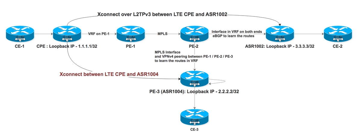
Bekijk nu hoe L2TPv3 Xconnect zich gedraagt wanneer VRF wordt gebruikt. Hier is de topologie die wordt gebruikt voor demonstratie waarin we Xconnect is geconfigureerd tussen CPE en ASR1002 (IP) en ASR1004 (MPLS) met eindpunten op ASR1000 in VRF (VRF Aware L2TPv3 wordt niet ondersteund op ASR1000-platform).
Testcase I: L2TPv3 Xconnect via IP-netwerk met eindpunten in VRF

PE-1 en PE-2 maken het MPLS-netwerk voor ISP. CPE is verbonden met PE-1 via VRF en ASR1002 is verbonden met PE-2 via VRF. ASR1002 heeft ook VRF op de interface aangesloten op PE-2. De bereikbaarheid van CPE loopback van ASR1002 is via VRF over IP interface.
Configuratie op CPE voor Xconnect richting ASR1002:
interface FastEthernet4.2381

encapsulation dot1Q 2381

xconnect 3.3.3.3 2381 encapsulation l2tpv3 pw-class PSEUDO_CLASS >>>>>>>>>>> Xconnect with ASR1002


pseudowire-class PSEUDO_CLASS

encapsulation l2tpv3

interworking vlan

protocol l2tpv3 L2TP_CLASS

ip local interface Loopback0

ip tos reflect


l2tp-class L2TP_CLASS

authentication

password cisco


interface Gigabit0/1

ip address 192.168.8.190 255.255.255.0

end


Interface Loopback0

ip address 1.1.1.1 255.255.255.255

end


ip route 0.0.0.0 0.0.0.0 192.168.8.1 >>>>>>>>>>>>>> Default route towards PE-1
Werkende configuratie op ASR1002:
interface GigabitEthernet0/0/0.906 —————————————————> Interface connected to PE-2 is in VRF

encapsulation dot1Q 906

ip vrf forwarding L2TP_VRF

ip address 10.1.1.1 255.255.255.252


interface GigabitEthernet0/0/1.2381

encapsulation dot1Q 2381

xconnect 1.1.1.1 2381 encapsulation l2tpv3 pw-class PSEUDO_CLASS


pseudowire-class PSEUDO_CLASS

encapsulation l2tpv3

interworking vlan

protocol l2tpv3 L2TP_CLASS

ip local interface Loopback11


l2tp-class L2TP_CLASS

authentication

password cisco


interface Loopback11

ip vrf forwarding L2TP_VRF ————————————————————————————> Source is in VRF

ip address 3.3.3.3 255.255.255.255


router bgp 1


address-family ipv4 vrf L2TP_VRF

redistribute connected

neighbor 10.1.1.2 remote-as 2 ———————————————> eBGP with PE-2 in VRF

neighbor 10.1.1.2 activate

neighbor 10.1.1.2 soft-reconfiguration inbound

exit-address-family
VRF L2TP_VRF:
B 1.1.1.1/32 [20/0] via 10.1.1.2, 1d ——————————> Xconnect end point learned via eBGP in VRF
Laten we nu de status van Xconnect op CPE controleren:
CPE #sh xconnect all de

Legend:    XC ST=Xconnect State  S1=Segment1 State  S2=Segment2 State

  UP=Up       DN=Down            AD=Admin Down      IA=Inactive

  SB=Standby  HS=Hot Standby     RV=Recovering      NH=No Hardware


XC ST  Segment 1                         S1 Segment 2                         S2

------+---------------------------------+--+---------------------------------+--


UP pri   ac Fa4.2381:2381(Eth VLAN)      UP l2tp 3.3.3.3:2381              DOWN

            Interworking: vlan                   Session ID: 1906980494

                                                 Tunnel ID: 2886222725

                                                Protocol State: DOWN

                                                Remote Circuit State: DOWN

                                                pw-class: PSEUDO_CLASS_VLAN
Het zegt dat Segment 2 down is, wat betekent dat het pad van CPE naar ASR1002 een probleem heeft. We kunnen het eindpunt pingen. De debugs op CPE laten zien dat de tunnel naar Endpoint is mislukt of dat er geen route naar het eindpunt is.
*Feb 15 08:12:47.225: L2TP _____:18136:8DF92CB9/uid:0[1.1.1.1/2381]: I CDN, flg TLS, ver 3, len 80

*Feb 15 08:12:47.225: L2TP _____:18136:8DF92CB9/uid:0[1.1.1.1/2381]:IETF v2:

*Feb 15 08:12:47.225: L2TP _____:18136:8DF92CB9/uid:0[1.1.1.1/2381]:Result Code

*Feb 15 08:12:47.225: L2TP _____:18136:8DF92CB9/uid:0[1.1.1.1/2381]:   Call disconnected for administrative reasons(3)

*Feb 15 08:12:47.225: L2TP _____:18136:8DF92CB9/uid:0[1.1.1.1/2381]:   Error code

*Feb 15 08:12:47.225: L2TP _____:18136:8DF92CB9/uid:0[1.1.1.1/2381]:     No error(0)

*Feb 15 08:12:47.225: L2TP _____:18136:8DF92CB9/uid:0[1.1.1.1/2381]:   Optional msg

*Feb 15 08:12:47.225: L2TP _____:18136:8DF92CB9/uid:0[1.1.1.1/2381]:       "Tunnel failed to 3.3.3.3" >>>>>>>>>>>>>>>>>

*Feb 15 08:12:47.225: L2TP _____:18136:8DF92CB9/uid:0[1.1.1.1/2381]:Cisco v3:
Het belangrijkste probleem hier is dat Endpoint bereikbaar is via VRF op ASR1002. Het Xconnect-eindpunt moet in de Global Routing Table staan om het te laten verschijnen. Laten we nu een route configureren voor CPE Loopback 1.1.1.1/32 in wereldwijde wijzende interface naar Gigabit Ethernet0/0/0.906 die zelf in VRF is.
 ip route 1.1.1.1 255.255.255.255 GigabitEthernet0/0/0.906 10.1.1.2


              S        1.1.1.1/32 [1/0] via 10.1.1.2, GigabitEthernet0/0/0.906
Zodra de statische route van de dummy is geconfigureerd, verschijnt Xconnect. Je kunt het ook naar Null0 verwijzen. Dit is een oplossing om de router te laten geloven dat Endpoint bereikbaar is via Global, niet via VRF en alleen wordt gebruikt voor Control Plane. Het werkelijke datavliegtuigverkeer zal alleen via VRF verlopen.
Dit zijn de ping resultaten met en zonder VRF:
ASR1002 #ping 1.1.1.1

Type escape sequence to abort.

Sending 5, 100-byte ICMP Echos to 1.1.1.1, timeout is 2 seconds:

.....

Success rate is 0 percent (0/5)


Ping vrf L2TP_VRF 1.1.1.1

Type escape sequence to abort.

Sending 5, 100-byte ICMP Echos to 1.1.1.1, timeout is 2 seconds:

!!!!!

Success rate is 100 percent (5/5), round-trip min/avg/max = 33/50/72 ms
Status van Xconnect op CPE:
CPE #sh xconnect all de

Legend:    XC ST=Xconnect State  S1=Segment1 State  S2=Segment2 State

  UP=Up       DN=Down            AD=Admin Down      IA=Inactive

  SB=Standby  HS=Hot Standby     RV=Recovering      NH=No Hardware


XC ST  Segment 1                         S1 Segment 2                         S2

------+---------------------------------+--+---------------------------------+--


UP pri   ac Fa4.2381:2381(Eth VLAN)      UP l2tp3.3.3.3:2381             UP

            Interworking: vlan                   Session ID: 1906980494

                                                 Tunnel ID: 2886222725

                                                Protocol State: UP

                                                Remote Circuit State: UP

                                                pw-class: PSEUDO_CLASS_VLAN
Testcase II: L2TPv3 Xconnect via MPLS-netwerk met eindpunten in VRF
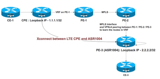
PE-1, PE-2 en PE-3 maken het MPLS-netwerk voor ISP met PE-2 als routereflector (RR). CPE is verbonden met PE-1 via VRF en ASR1004 is verbonden met PE-2 met MPLS ingeschakeld op de interface. ASR1004 heeft ook VRF waarin het de VPNv4-routes van PE-1 via RR zou moeten ontvangen. De bereikbaarheid van CPE looback van ASR1004 is via VRF via MPLS interface.
Configuratie op CPE voor Xconnect richting ASR1004:
interface FastEthernet4.2380

encapsulation dot1Q 2380

xconnect 2.2.2.2 2380 encapsulation l2tpv3 pw-class PSEUDO_CLASS  >>>>>>>>>>Xconnect with ASR1004


interface FastEthernet4.2381

encapsulation dot1Q 2381

xconnect 3.3.3.3 2381 encapsulation l2tpv3 pw-class PSEUDO_CLASS >>>>>>>>>>> Xconnect with ASR1002


pseudowire-class PSEUDO_CLASS

encapsulation l2tpv3

interworking vlan

protocol l2tpv3 L2TP_CLASS

ip local interface Loopback0

ip tos reflect


l2tp-class L2TP_CLASS

authentication

password cisco


interface Gigabit0/1

ip address 192.168.8.190 255.255.255.0

end


Interface Loopback0

ip address 1.1.1.1 255.255.255.255

end


ip route 0.0.0.0 0.0.0.0 192.168.8.1 >>>>>>>>>>>>>> Default route towards PE-1
Configuratie op ASR1004:
interface GigabitEthernet0/0/1

no ip address

negotiation auto

service instance 2 ethernet

encapsulation dot1q 2380

xconnect 1.1.1.1 2380 encapsulation l2tpv3 pw-class PSEUDO_CLASS_VLAN

!

end


interface Loopback11

ip vrf forwarding L2TP_VRF —————————————————> Source Loopback in in VRF

ip address 2.2.2.2 255.255.255.255

end


pseudowire-class PSEUDO_CLASS_VLAN

encapsulation l2tpv3

interworking vlan

protocol l2tpv3 L2TP_CLASS

ip local interface Loopback11


l2tp-class L2TP_CLASS

authentication

password cisco


router bgp 2

address-family ipv4 vrf L2TP_VRF

redistribute connected

redistribute static

default-information originate

exit-address-family
Routevermelding voor Xconnect-eindpunt:
ASR1004#sh ip rou vrf L2TP_VRF 1.1.1.1 .   ——————————————————> Xconnect End Point also learned via VRF

Routing Table: L2TP_VRF
Routing entry for 1.1.1.1/32
 Known via "bgp 2", distance 200, metric 0, type internal
 Last update from 11.11.11.11 6d17h ago
 Routing Descriptor Blocks:
 * 11.11.11.11 (default), from 22.22.22.22, 6d17h ago
 Route metric is 0, traffic share count is 1
 AS Hops 0
 MPLS label: 18
 MPLS Flags: MPLS Required


We observed that Segment 2 was continuously flapping on both ends.


ASR1004#sh xc all de

Legend:    XC ST=Xconnect State  S1=Segment1 State  S2=Segment2 State

  UP=Up       DN=Down            AD=Admin Down      IA=Inactive

  SB=Standby  HS=Hot Standby     RV=Recovering      NH=No Hardware


XC ST  Segment 1                         S1 Segment 2                         S2

------+---------------------------------+--+---------------------------------+--

DN pri   ac Gi0/0/1:2380(Eth VLAN)       UP l2tp 1.1.1.1:2380           DN  >>>>>>>>>>>>>>

            Interworking: vlan                   Session ID: 2543426569

                                                 Tunnel ID: 3352120314

                                                 Protocol State: DOWN

                                                 Remote Circuit State: DOWN

                                                 pw-class: PSEUDO_CLASS_VLAN

ASR1004#sh xc all de

Legend:    XC ST=Xconnect State  S1=Segment1 State  S2=Segment2 State

  UP=Up       DN=Down            AD=Admin Down      IA=Inactive

  SB=Standby  HS=Hot Standby     RV=Recovering      NH=No Hardware


XC ST  Segment 1                         S1 Segment 2                         S2

------+---------------------------------+--+---------------------------------+--

UP pri   ac Gi0/0/1:2380(Eth VLAN)       UP l2tp 1.1.1,1:2380           UP >>>>>>>>>>>>>>>>

            Interworking: vlan                   Session ID: 2543426569

                                                 Tunnel ID: 3352120314

                                                 Protocol State: UP

                                                 Remote Circuit State: UP

                                                 pw-class: PSEUDO_CLASS_VLAN
Logs van CPE:
CPE#sh xconnect all de

Legend:    XC ST=Xconnect State  S1=Segment1 State  S2=Segment2 State

  UP=Up       DN=Down            AD=Admin Down      IA=Inactive

  SB=Standby  HS=Hot Standby     RV=Recovering      NH=No Hardware


XC ST  Segment 1                         S1 Segment 2                         S2

------+---------------------------------+--+---------------------------------+--

DN pri   ac Fa4.2380:2380(Eth VLAN)      UP l2tp 2.2.2.2:2380            DN ---------------à Flapping with ASR1004

            Interworking: vlan                   Session ID: 3434660693

                                                 Tunnel ID: 1760690853

                                                 Protocol State: DOWN

                                                 Remote Circuit State: DOWN

                                                 pw-class: PSEUDO_CLASS

UP pri   ac Fa4.2381:2381(Eth VLAN)      UP l2tp 3.3.3.3:2381              UP ---------------------à Stable with ASR1002

            Interworking: vlan                   Session ID: 1906980494

                                                 Tunnel ID: 2886222725

                                                 Protocol State: UP

                                                 Remote Circuit State: UP

                                                 pw-class: PSEUDO_CLASS


CPE#sh l2tp session


L2TP Session Information Total tunnels 2 sessions 2


LocID      RemID      TunID      Username, Intf/      State  Last Chg Uniq ID

                                 Vcid, Circuit

2714490989 3697021268 1760690853 2380, Fa4.2380:2380  est   00:00:03 0  ————————> Flapping with ASR1004

1906980494 2361475239 2886222725 2381, Fa4.2381:2381  est   15:37:06 0       ————————> Stable with ASR1002
U kunt in dit geval geen statische route configureren omdat de afsluitinterface een MPLS-interface is. Als een tijdelijke oplossing zijn er twee interfaces die naar elkaar zijn teruggeleid en in VRF met elkaar zijn geconfigureerd. Vervolgens werd een statische route geconfigureerd in globale richting die naar de VRF-interface wees, waarbij deze Xconnect stabiel werd.
ASR1004#sh run int gi0/0/2

Building configuration...


Current configuration : 95 bytes

!

interface GigabitEthernet0/0/2 ——————————> Looped to Gi0/0/3

ip address 20.20.20.2 255.255.255.252

negotiation auto

end


#sh run int gi0/0/3

Building configuration...


Current configuration : 126 bytes

!

interface GigabitEthernet0/0/3

ip vrf forwarding L2TP_VRF

ip address 20.20.20.1 255.255.255.252

negotiation auto

end


ip route 10.246.131.62 255.255.255.255 20.20.20.1 ———————> Static route pointing towards an IP interface in Global


CPE#sh xconnect all de

Legend:    XC ST=Xconnect State  S1=Segment1 State  S2=Segment2 State

  UP=Up       DN=Down            AD=Admin Down      IA=Inactive

  SB=Standby  HS=Hot Standby     RV=Recovering      NH=No Hardware


XC ST  Segment 1                         S1 Segment 2                         S2

------+---------------------------------+--+---------------------------------+--

DN pri   ac Fa4.2380:2380(Eth VLAN)      UP l2tp 2.2.2.2:2380            UP

            Interworking: vlan                   Session ID: 3434660693

                                                 Tunnel ID: 1760690853

                                                 Protocol State: DOWN

                                                 Remote Circuit State: DOWN

                                                 pw-class: PSEUDO_CLASS

UP pri   ac Fa4.2381:2381(Eth VLAN)      UP l2tp 3.3.3.3:2381              UP

            Interworking: vlan                   Session ID: 1906980494

                                                 Tunnel ID: 2886222725

                                                 Protocol State: UP

                                                 Remote Circuit State: UP

                                                 pw-class: PSEUDO_CLASS


CPE#sh l2tp session
L2TP Sessiegegevens Totaal tunnels 2 sessies 2:
LocID      RemID      TunID      Username, Intf/      State  Last Chg Uniq ID

                                 Vcid, Circuit

2714490989 3697021268 1760690853 2380, Fa4.2380:2380  est   00:20:03 0

1906980494 2361475239 2886222725 2381, Fa4.2381:2381  est   15:37:06 0
De verkeersstroom wordt gezien als in het geval van ASR1004:
- Wanneer verkeer afkomstig is van CPE op ASR1004, wordt het geleverd in MPLS-interface Gi0/0/1 en wordt het rechtstreeks overgeschakeld naar Gi0/0/0 Access-poort.
- Wanneer verkeer afkomstig is van toegangspoort Gi0/0/0, neemt het het lus-pad van Gi0/0/0 -> Gi0/0/2 -> Gi0/0/3 -> Gi0/0/1.
Het belangrijkste probleem met deze oplossing is voor QFP-gebruik op ASR1000-platform, omdat pakketverwerking twee keer wordt uitgevoerd:
ASR1004#  show platform packet-trace summary

Pkt   Input             Output            State  Reason

0     Gi0/0/3           Gi0/0/1           FWD

1     Gi0/0/3           Gi0/0/1           FWD

2     Gi0/0/3           Gi0/0/1           FWD

3     Gi0/0/0           Gi0/0/2           FWD

4     Gi0/0/0           Gi0/0/2           FWD

5     Gi0/0/0           Gi0/0/2           FWD

6     Gi0/0/0           Gi0/0/2           FWD

7     Gi0/0/0           Gi0/0/2           FWD
Dit gedrag is beschreven in Doc Bug: CSCvi42964
Bijgedragen door Cisco-engineers
- Yogita BansalCisco TAC Engineer
 Feedback
Contact Cisco
- Een ondersteuningscase openen

- (Vereist een Cisco-servicecontract)