Cisco Nexus 7000 シリーズ NX-OS レイヤ 2 スイッチング コンフィギュレーション ガイド
偏向のない言語
この製品のマニュアルセットは、偏向のない言語を使用するように配慮されています。このマニュアルセットでの偏向のない言語とは、年齢、障害、性別、人種的アイデンティティ、民族的アイデンティティ、性的指向、社会経済的地位、およびインターセクショナリティに基づく差別を意味しない言語として定義されています。製品ソフトウェアのユーザーインターフェイスにハードコードされている言語、RFP のドキュメントに基づいて使用されている言語、または参照されているサードパーティ製品で使用されている言語によりドキュメントに例外が存在する場合があります。シスコのインクルーシブランゲージに対する取り組みの詳細は、こちらをご覧ください。
翻訳について
このドキュメントは、米国シスコ発行ドキュメントの参考和訳です。リンク情報につきましては、日本語版掲載時点で、英語版にアップデートがあり、リンク先のページが移動/変更されている場合がありますことをご了承ください。あくまでも参考和訳となりますので、正式な内容については米国サイトのドキュメントを参照ください。
- Updated:
- 2017年6月22日
章のタイトル: Cisco NX-OS を使用した STP 拡張の設定
目次
- Cisco NX-OS を使用した STP 拡張の設定
- Information About STP Extensions
- STP Port Types
- STP Edge Ports
- Bridge Assurance
- BPDU ガード
- BPDU フィルタリング
- Loop Guard
- Root Guard
- STP 拡張機能の適用
- PVST Simulation
- High Availability for STP
- Virtualization Support for STP Extensions
- Licensing Requirements for STP Extensions
- Prerequisites for STP Extensions
- Guidelines and Limitations for Configuring STP Extensions
- STP 拡張機能のデフォルト設定
- Configuring STP Extensions Steps
- スパニングツリー ポート タイプのグローバルな設定
- 指定インターフェイスでのスパニングツリー エッジ ポートの設定
- 指定インターフェイスでのスパニングツリー ネットワーク ポートの設定
- BPDU ガードのグローバルなイネーブル化
- 指定インターフェイスでの BPDU ガードのイネーブル化
- BPDU フィルタリングのグローバルなイネーブル化
- 指定インターフェイスでの BPDU フィルタリングのイネーブル化
- ループ ガードのグローバルなイネーブル化
- 指定インターフェイスでのループ ガードまたはルート ガードのイネーブル化
- PVST シミュレーションのグローバル設定(CLI バージョン)
- ポートごとの PVST シミュレーションの設定
- STP 拡張機能の設定の確認
- STP 拡張機能の設定例
- STP 拡張機能の追加情報(CLI バージョン)
- STP 拡張機能の設定の機能履歴(CLI バージョン)
この章では、Cisco NX-OS デバイスでスパニングツリー プロトコル(STP)拡張機能を設定する方法について説明します。
この章は、次の内容で構成されています。
- Information About STP Extensions
- Licensing Requirements for STP Extensions
- Prerequisites for STP Extensions
- Guidelines and Limitations for Configuring STP Extensions
- STP 拡張機能のデフォルト設定
- Configuring STP Extensions Steps
- STP 拡張機能の設定の確認
- STP 拡張機能の設定例
- STP 拡張機能の追加情報(CLI バージョン)
- STP 拡張機能の設定の機能履歴(CLI バージョン)
Information About STP Extensions
 (注) |
See the 『Cisco Nexus 7000 Series NX-OS Interfaces Configuration Guide, Release 6.x』, for information on creating Layer 2 interfaces. |
Cisco has added extensions to STP that enhances loop prevention, protects against some possible user misconfigurations, and provides better control over the protocol parameters. Although, in some cases, similar functionality may be incorporated into the IEEE 802.1w Rapid Spanning Tree Protocol (RSTP) standard, we recommend using these extensions. All of these extensions, except PVST Simulation, can be used with both Rapid PVST+ and MST. You use PVST Simulation only with MST.
The available extensions are spanning tree edge ports (which supply the functionality previously known as PortFast), Bridge Assurance, BPDU Guard, BPDU Filtering, Loop Guard, Root Guard, and PVT Simulation. Many of these features can be applied either globally or on specified interfaces.
(注) |
Spanning tree is used to refer to IEEE 802.1w and IEEE 802.1s. If the text is discussing the IEEE 802.1D Spanning Tree Protocol, 802.1D is stated specifically. |
- STP Port Types
- Bridge Assurance
- BPDU ガード
- BPDU フィルタリング
- Loop Guard
- Root Guard
- STP 拡張機能の適用
- PVST Simulation
- High Availability for STP
- Virtualization Support for STP Extensions
STP Port Types
You can configure a spanning tree port as an edge port, a network port, or a normal port. A port can be in only one of these states at a given time. The default spanning tree port type is normal.
Edge ports, which are connected to Layer 2 hosts, can be either an access port or a trunk port.
(注) |
If you configure a port connected to a Layer 2 switch or bridge as an edge port, you might create a bridging loop. |
Network ports are connected only to Layer 2 switches or bridges.
(注) |
If you mistakenly configure ports that are connected to Layer 2 hosts, or edge devices, as spanning tree network ports, those ports will automatically move into the blocking state. |
STP Edge Ports
You connect STP edge ports only to Layer 2 hosts. The edge port interface immediately transitions to the forwarding state, without moving through the blocking or learning states. (This immediate transition was previously configured as the Cisco-proprietary feature PortFast.)
Interfaces that are connected to Layer 2 hosts should not receive STP bridge protocol data units (BPDUs).
Bridge Assurance
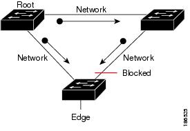
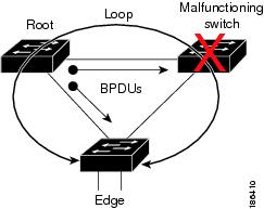
You can use Bridge Assurance to protect against certain problems that can cause bridging loops in the network. Specifically, you use Bridge Assurance to protect against a unidirectional link failure or other software failure and a device that continues to forward data traffic when it is no longer running the spanning tree algorithm.
(注) |
Bridge Assurance is supported only by Rapid PVST+ and MST. |
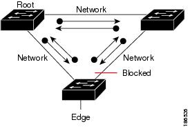
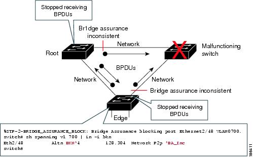
Bridge Assurance is enabled by default and can only be disabled globally. Also, Bridge Assurance can be enabled only on spanning tree network ports that are point-to-point links. Finally, both ends of the link must have Bridge Assurance enabled. If the device on one side of the link has Bridge Assurance enabled and the device on the other side either does not support Bridge Assurance or does not have this feature enabled, the connecting port is blocked.
With Bridge Assurance enabled, BPDUs are sent out on all operational network ports, including alternate and backup ports, for each hello time period. If the port does not receive a BPDU for a specified period, the port moves into the blocking state and is not used in the root port calculation. Once that port receives a BPDU, it resumes the normal spanning tree transitions.
BPDU ガード
BPDU ガードをイネーブルにすると、BPDU を受信したときにそのインターフェイスがシャットダウンされます。
BPDU ガードはインターフェイス レベルで設定できます。 BPDU ガードをインターフェイス レベルで設定すると、そのポートはポート タイプ設定にかかわらず BPDU を受信するとすぐにシャットダウンされます。
BPDU ガードをグローバル単位で設定すると、動作中のスパニング ツリー エッジ ポート上だけで有効となります。 有効な設定では、レイヤ 2 LAN エッジ インターフェイスは BPDU を受信しません。 レイヤ 2 LAN エッジ インターフェイスが BPDU を受信した場合、許可されていないデバイスの接続と同様に、無効な設定として通知されます。 BPDU ガードをグローバル単位でイネーブルにすると、BPDU を受信したすべてのスパニング ツリー エッジ ポートがシャットダウンされます。
BPDU ガードでは、無効な設定が通知された場合、レイヤ 2 LAN インターフェイスを手動で再起動させる必要があるので、無効な設定に対して安全に対応できます。
(注) |
BPDU ガードをグローバル単位でイネーブルにすると、動作中のすべてのスパニング ツリー エッジ インターフェイスに適用されます。 |
BPDU フィルタリング
BPDU フィルタリングを使用すると、デバイスの特定のポート上で BPDU が送信されないように、または BPDU を受信しないように設定できます。
グローバルに設定された BPDU フィルタリングは、動作中のすべてのスパニング ツリー エッジ ポートに適用されます。 エッジ ポートはホストだけに接続してください。ホストでは通常、BPDU は破棄されます。 動作中のスパニング ツリー エッジ ポートが BPDU を受信すると、ただちに標準のスパニング ツリー ポート タイプに戻り、通常のポート状態遷移が行われます。 その場合、当該ポートで BPDU フィルタリングはディセーブルとなり、スパニング ツリーによって、同ポートでの BPDU の送信が再開されます。
BPDU フィルタリングは、インターフェイスごとに設定することもできます。 BPDU フィルタリングを特定のポートに明示的に設定すると、そのポートは BPDU を送出しなくなり、受信した BPDU をすべてドロップします。 特定のインターフェイスを設定することによって、個々のポート上のグローバルな BPDU フィルタリングの設定を実質的に上書きできます。 このようにインターフェイスに対して実行された BPDU フィルタリングは、そのインターフェイスがトランキングであるか否かに関係なく、インターフェイス全体に適用されます。
 注意 |
BPDU フィルタリングをインターフェイスごとに設定するときは注意が必要です。 ホストに接続されていないポートに BPDU フィルタリングを明示的に設定すると、ブリッジング ループに陥る可能性があります。このようなポートは受信した BPDU をすべて無視して、フォワーディング ステートに移行するからです。 |
| ポート単位の BPDU フィルタリングの設定 |
グローバルな BPDU フィルタリングの設定 |
STP エッジ ポート設定 |
BPDU フィルタリングの状態 |
|---|---|---|---|
| デフォルト 1 |
イネーブル |
イネーブル |
イネーブル 2 |
| デフォルト |
イネーブル |
ディセーブル |
ディセーブル |
| デフォルト |
ディセーブル |
N/A |
ディセーブル |
| ディセーブル |
N/A |
N/A |
ディセーブル |
| イネーブル |
N/A |
N/A |
イネーブル |
Loop Guard
Loop Guard helps prevent bridging loops that could occur because of a unidirectional link failure on a point-to-point link.
An STP loop occurs when a blocking port in a redundant topology erroneously transitions to the forwarding state. Transitions are usually caused by a port in a physically redundant topology (not necessarily the blocking port) that stops receiving BPDUs.
When you enable Loop Guard globally, it is useful only in switched networks where devices are connected by point-to-point links. On a point-to-point link, a designated bridge cannot disappear unless it sends an inferior BPDU or brings the link down. However, you can enable Loop Guard on shared links per interface,
You can use Loop Guard to determine if a root port or an alternate/backup root port receives BPDUs. If the port that was previously receiving BPDUs is no longer receiving BPDUs, Loop Guard puts the port into an inconsistent state (blocking) until the port starts to receive BPDUs again. If such a port receives BPDUs again, the port—and link—is deemed viable again. The protocol removes the loop-inconsistent condition from the port, and the STP determines the port state because the recovery is automatic.
Loop Guard isolates the failure and allows STP to converge to a stable topology without the failed link or bridge. Disabling Loop Guard moves all loop-inconsistent ports to the listening state.
You can enable Loop Guard on a per-port basis. When you enable Loop Guard on a port, it is automatically applied to all of the active instances or VLANs to which that port belongs. When you disable Loop Guard, it is disabled for the specified ports.
Enabling Loop Guard on a root device has no effect but provides protection when a root device becomes a nonroot device.
Root Guard
When you enable Root Guard on a port, Root Guard does not allow that port to become a root port. If a received BPDU triggers an STP convergence that makes that designated port become a root port, that port is put into a root-inconsistent (blocked) state. After the port stops sending superior BPDUs, the port is unblocked again. Through STP, the port moves to the forwarding state. Recovery is automatic.
When you enable Root Guard on an interface, this functionality applies to all VLANs to which that interface belongs.
You can use Root Guard to enforce the root bridge placement in the network. Root Guard ensures that the port on which Root Guard is enabled is the designated port. Normally, root bridge ports are all designated ports, unless two or more of the ports of the root bridge are connected. If the bridge receives superior BPDUs on a Root Guard-enabled port, the bridge moves this port to a root-inconsistent STP state. In this way, Root Guard enforces the position of the root bridge.
You cannot configure Root Guard globally.
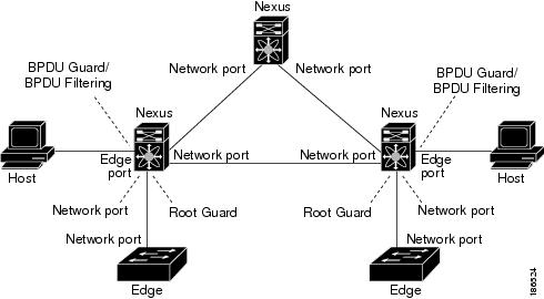
STP 拡張機能の適用
この図に示すように、ネットワーク上に各種の STP 拡張機能を設定することを推奨します。 Bridge Assurance は、ネットワーク全体でイネーブルになります。 ホスト インターフェイス上で、BPDU ガードと BPDU フィルタリングのいずれかをイネーブルにすることをお勧めします。
PVST Simulation
MST interoperates with Rapid PVST+ with no need for user configuration. The PVST simulation feature enables this interoperability.
(注) |
PVST simulation is enabled by default when you enable MST. By default, all interfaces on the device interoperate between MST and Rapid PVST+. |
However, you may want to control the connection between MST and Rapid PVST+ to protect against accidentally connecting an MST-enabled port to a port enabled to run Rapid PVST+. Because Rapid PVST+ is the default STP mode, you may encounter many Rapid PVST+ connections.
Disabling Rapid PVST+ simulation, which can be done per port or globally for the entire device, moves the MST-enabled port to the blocking state once it detects it is connected to a Rapid PVST+-enabled port. This port remains in the inconsistent state until the port stops receiving Rapid PVST+/SSTP BPDUs, and then the port resumes the normal STP transition process.
The root bridge for all STP instances must all be in either the MST region or the Rapid PVST+ side. If the root bridge for all STP instances are not on one side or the other, the software moves the port into a PVST simulation-inconsistent state.
(注) |
We recommend that you put the root bridge for all STP instances in the MST region. |
High Availability for STP
The software supports high availability for STP. However, the statistics and timers are not restored when STP restarts. The timers start again and the statistics begin from 0.
(注) |
See the 『Cisco Nexus 7000 Series NX-OS High Availability and Redundancy Guide』, for complete information on high-availability features. |
Virtualization Support for STP Extensions
The system provides support for virtual device contexts (VDCs), and each VDC runs a separate STP. You can run Rapid PVST+ in one VDC and MST in another VDC.
(注) |
See the 『Cisco Nexus 7000 Series NX-OS Virtual Device Context Configuration Guide』, for complete information on VDCs and assigning resources. |
Licensing Requirements for STP Extensions
The following table shows the licensing requirements for this feature:
However, using VDCs requires an Advanced Services license.
Prerequisites for STP Extensions
STP has the following prerequisites:
Guidelines and Limitations for Configuring STP Extensions
STP extensions have the following configuration guidelines and limitations:
- Connect STP network ports only to switches.
- You should configure host ports as STP edge ports and not as network ports.
- If you enable STP network port types globally, ensure that you manually configure all ports connected to hosts as STP edge ports.
- You should configure all access and trunk ports connected to Layer 2 hosts as edge ports.
- Bridge Assurance runs only on point-to-point spanning tree network ports. You must configure each side of the link for this feature.
- We recommend that you enable Bridge Assurance throughout your network.
- We recommend that you enable BPDU Guard on all edge ports.
- Enabling Loop Guard globally works only on point-to-point links.
- Enabling Loop Guard per interface works on both shared and point-to-point links.
- Root Guard forces a port to always be a designated port; it does not allow a port to become a root port. Loop Guard is effective only if the port is a root port or an alternate port. You cannot enable Loop Guard and Root Guard on a port at the same time.
- Loop Guard has no effect on a disabled spanning tree instance or a VLAN.
- Spanning tree always chooses the first operational port in the channel to send the BPDUs. If that link becomes unidirectional, Loop Guard blocks the channel, even if other links in the channel are functioning properly.
- If you group together a set of ports that are already blocked by Loop Guard to form a channel, spanning tree loses all the state information for those ports and the new channel port may obtain the forwarding state with a designated role.
-
If a channel is blocked by Loop Guard and the channel members go back to an individual link status, spanning tree loses all the state information. The individual physical ports may obtain the forwarding state with the designated role, even if one or more of the links that formed the channel are unidirectional.
(注)
You can enable UniDirectional Link Detection (UDLD) aggressive mode to isolate the link failure. A loop may occur until UDLD detects the failure, but Loop Guard will not be able to detect it. See the 『Cisco Nexus 7000 Series NX-OS Interfaces Configuration Guide, Release 6.x』, for information on UDLD.
- You should enable Loop Guard globally on a switch network with physical loops.
- You should enable Root Guard on ports that connect to network devices that are not under direct administrative control.
STP 拡張機能のデフォルト設定
| パラメータ |
デフォルト |
|---|---|
| ポート タイプ |
標準 |
| Bridge Assurance |
イネーブル(STP ネットワーク ポートのみ) |
| グローバル BPDU ガード |
ディセーブル |
| インターフェイス単位の BPDU ガード |
ディセーブル |
| グローバル BPDU フィルタリング |
ディセーブル |
| インターフェイス単位の BPDU フィルタリング |
ディセーブル |
| グローバル ループ ガード |
ディセーブル |
| インターフェイス単位のループ ガード |
ディセーブル |
| インターフェイス単位のルート ガード |
ディセーブル |
| PVST シミュレーション |
イネーブル |
Configuring STP Extensions Steps
(注) |
If you are familiar with the Cisco IOS CLI, be aware that the Cisco NX-OS commands for this feature might differ from the Cisco IOS commands that you would use. |
You can enable Loop Guard per interface on either shared or point-to-point links.
- スパニングツリー ポート タイプのグローバルな設定
- 指定インターフェイスでのスパニングツリー エッジ ポートの設定
- 指定インターフェイスでのスパニングツリー ネットワーク ポートの設定
- BPDU ガードのグローバルなイネーブル化
- 指定インターフェイスでの BPDU ガードのイネーブル化
- BPDU フィルタリングのグローバルなイネーブル化
- 指定インターフェイスでの BPDU フィルタリングのイネーブル化
- ループ ガードのグローバルなイネーブル化
- 指定インターフェイスでのループ ガードまたはルート ガードのイネーブル化
- PVST シミュレーションのグローバル設定(CLI バージョン)
- ポートごとの PVST シミュレーションの設定
スパニングツリー ポート タイプのグローバルな設定
スパニングツリー ポート タイプの指定は、次のように、ポートの接続先デバイスによって異なります。
- エッジ:エッジ ポートは、レイヤ 2 ホストに接続するアクセス ポートです。
- ネットワーク:ネットワーク ポートは、レイヤ 2 スイッチまたはブリッジだけに接続し、アクセス ポートまたはトランク ポートのいずれかになります。
- 標準:標準ポートはエッジ ポートでもネットワーク ポートでもない、標準のスパニングツリー ポートです。 これらのポートは、どのデバイスにも接続できます。
ポート タイプは、グローバル単位でもインターフェイス単位でも設定できます。 デフォルトのスパニングツリー ポート タイプは「標準」です。
スパニングツリー ポート タイプを設定する前に、次の点を確認してください。
1. config t
2. 次の 2 つのコマンドのいずれかを入力します。
3. exit
4. (任意) show spanning-tree
5. (任意) copy running-config startup-config
手順の詳細
次に、レイヤ 2 ホストに接続しているすべてのアクセス ポートをスパニングツリー エッジ ポートとして設定する例を示します。
switch# config t switch(config)# spanning-tree port type edge default switch(config)# exit switch#
次に、レイヤ 2 スイッチまたはブリッジに接続しているすべてのポートを、スパニングツリー ネットワーク ポートとして設定する例を示します。
switch# config t
switch(config)# spanning-tree port type network default
switch(config)#
指定インターフェイスでのスパニングツリー エッジ ポートの設定
指定インターフェイスにスパニングツリー エッジ ポートを設定できます。 スパニングツリー エッジ ポートとして設定されたインターフェイスは、リンク アップ時に、ブロッキング ステートやラーニング ステートを経由することなく、フォワーディング ステートに直接移行します。
このコマンドには次の 4 つの状態があります。
- spanning-tree port type edge:このコマンドはアクセス ポートのエッジ動作を明示的にイネーブルにします。
- spanning-tree port type edge trunk:このコマンドはトランク ポートのエッジ動作を明示的にイネーブルにします。
(注) |
spanning-tree port type edge trunk コマンドを入力すると、そのポートは、アクセス モードであってもエッジ ポートとして設定されます。 |
- spanning-tree port type normal:このコマンドは、ポートを標準スパニングツリー ポートとして明示的に設定しますが、フォワーディング ステートへの直接移行はイネーブルにしません。
- no spanning-tree port type:このコマンドは、spanning-tree port type edge default コマンドをグローバル コンフィギュレーション モードで定義した場合に、エッジ動作を暗黙的にイネーブルにします。 エッジ ポートをグローバルに設定していない場合、no spanning-tree port type コマンドは、spanning-tree port type normal コマンドと同じです。
スパニングツリー ポート タイプを設定する前に、次の点を確認してください。
1. config t
2. interface type slot/port
3. spanning-tree port type edge
4. exit
5. (任意) show spanning-tree
6. (任意) copy running-config startup-config
手順の詳細
| コマンドまたはアクション | 目的 | |
|---|---|---|
| ステップ 1 | config t 例: switch# config t switch(config)# |
コンフィギュレーション モードを開始します。 |
| ステップ 2 | interface type slot/port 例: switch(config)# interface ethernet 1/4 switch(config-if)# |
設定するインターフェイスを指定し、インターフェイス コンフィギュレーション モードを開始します。 |
| ステップ 3 | spanning-tree port type edge 例: switch(config-if)# spanning-tree port type edge
|
指定したアクセス インターフェイスをスパニング エッジ ポートに設定します。 エッジ ポートは、リンク アップすると、ブロッキング ステートやラーニング ステートを経由することなく、フォワーディング ステートに直接移行します。 デフォルトのスパニングツリー ポート タイプは「標準」です。 |
| ステップ 4 | exit 例: switch(config-if)# exit switch(config)# |
インターフェイス コンフィギュレーション モードを終了します。 |
| ステップ 5 | show spanning-tree 例: switch# show spanning-tree |
(任意) 設定した STP ポート タイプを含む STP コンフィギュレーションを表示します。 |
| ステップ 6 | copy running-config startup-config 例: switch# copy running-config startup-config |
(任意) 実行コンフィギュレーションを、スタートアップ コンフィギュレーションにコピーします。 |
次に、アクセス インターフェイス Ethernet 1/4 をスパニングツリー エッジ ポートとして設定する例を示します。
switch# config t switch(config)# interface ethernet 1/4 switch(config-if)# spanning-tree port type edge switch(config-if)# exit switch(config)#
指定インターフェイスでのスパニングツリー ネットワーク ポートの設定
指定インターフェイスにスパニングツリー ネットワーク ポートを設定できます。
Bridge Assurance は、スパニングツリー ネットワーク ポート上だけで実行されます。
このコマンドには次の 3 つの状態があります。
- spanning-tree port type network:このコマンドは指定したポートを明示的にネットワーク ポートとして設定します。 Bridge Assurance をグローバルにイネーブルにすると、スパニングツリー ネットワーク ポート上で Bridge Assurance が自動的に実行されます。
- spanning-tree port type normal:このコマンドは、ポートを明示的に標準スパニングツリー ポートとして設定します。このインターフェイス上では Bridge Assurance は動作しません。
- no spanning-tree port type:このコマンドは、spanning-tree port type network default コマンドをグローバル コンフィギュレーション モードで定義した場合に、ポートを暗黙的にスパニングツリー ネットワーク ポートとしてイネーブルにします。 Bridge Assurance をイネーブルにすると、このポート上で Bridge Assurance が自動的に実行されます。
(注) |
レイヤ 2 ホストに接続しているポートをネットワーク ポートとして設定すると、自動的にブロッキング ステートに移行します。 |
スパニングツリー ポート タイプを設定する前に、次の点を確認してください。
1. config t
2. interface type slot/port
3. spanning-tree port type network
4. exit
5. (任意) show spanning-tree
6. (任意) copy running-config startup-config
手順の詳細
| コマンドまたはアクション | 目的 | |
|---|---|---|
| ステップ 1 | config t 例: switch# config t switch(config)# |
コンフィギュレーション モードを開始します。 |
| ステップ 2 | interface type slot/port 例: switch(config)# interface ethernet 1/4 switch(config-if)# |
設定するインターフェイスを指定し、インターフェイス コンフィギュレーション モードを開始します。 |
| ステップ 3 | spanning-tree port type network 例: switch(config-if)# spanning-tree port type network
|
指定したインターフェイスをスパニング ネットワーク ポートに設定します。 Bridge Assurance をイネーブルにすると、各ネットワーク ポート上で Bridge Assurance が自動的に実行されます。 デフォルトのスパニングツリー ポート タイプは「標準」です。 |
| ステップ 4 | exit 例: switch(config-if)# exit switch(config)# |
インターフェイス コンフィギュレーション モードを終了します。 |
| ステップ 5 | show spanning-tree 例: switch# show spanning-tree |
(任意) 設定した STP ポート タイプを含む STP コンフィギュレーションを表示します。 |
| ステップ 6 | copy running-config startup-config 例: switch# copy running-config startup-config |
(任意) 実行コンフィギュレーションを、スタートアップ コンフィギュレーションにコピーします。 |
次に、Ethernet インターフェイス 1/4 をスパニングツリー ネットワーク ポートとして設定する例を示します。
switch# config t switch(config)# interface ethernet 1/4 switch(config-if)# spanning-tree port type network switch(config-if)# exit switch(config)#
BPDU ガードのグローバルなイネーブル化
BPDU ガードをデフォルトでグローバルにイネーブルにできます。 BPDU ガードがグローバルにイネーブルにされると、システムは、BPDU を受信したエッジ ポートをシャット ダウンします。
(注) |
すべてのエッジ ポートで BPDU ガードをイネーブルにすることを推奨します。 |
スパニングツリー ポート タイプを設定する前に、次の点を確認してください。
1. config t
2. spanning-tree port type edge bpduguard default
3. exit
4. (任意) show spanning-tree summary
5. (任意) copy running-config startup-config
手順の詳細
| コマンドまたはアクション | 目的 | |
|---|---|---|
| ステップ 1 | config t 例: switch# config t switch(config)# |
コンフィギュレーション モードを開始します。 |
| ステップ 2 | spanning-tree port type edge bpduguard default 例: switch(config)# spanning-tree port type edge bpduguard default
|
すべてのスパニングツリー エッジ ポートで、BPDU ガードを、デフォルトでイネーブルにします。 デフォルトでは、グローバルな BPDU ガードはディセーブルです。 |
| ステップ 3 | exit 例: switch(config)# exit switch# |
コンフィギュレーション モードを終了します。 |
| ステップ 4 | show spanning-tree summary 例: switch# show spanning-tree summary |
(任意) STP の概要を表示します。 |
| ステップ 5 | copy running-config startup-config 例: switch# copy running-config startup-config |
(任意) 実行コンフィギュレーションを、スタートアップ コンフィギュレーションにコピーします。 |
次に、すべてのスパニングツリー エッジ ポートで BPDU ガードをイネーブルにする例を示します。
switch# config t switch(confiig)# spanning-tree port type edge bpduguard default switch(config)# exit switch#
指定インターフェイスでの BPDU ガードのイネーブル化
指定インターフェイスで、BPDU ガードをイネーブルにできます。 BPDU ガードがイネーブルにされたポートは、BPDU を受信すると、シャットダウンされます。
BPDU ガードは、指定インターフェイスで次のように設定にできます。
この機能を設定する前に、次の点を確認してください。
1. config t
2. interface type slot/port
3. 次のいずれかのコマンドを入力します。
4. exit
5. (任意) show spanning-tree summary
6. (任意) copy running-config startup-config
手順の詳細
| コマンドまたはアクション | 目的 | |||||||
|---|---|---|---|---|---|---|---|---|
| ステップ 1 | config t 例: switch# config t switch(config)# |
コンフィギュレーション モードを開始します。 |
||||||
| ステップ 2 | interface type slot/port 例: switch(config)# interface ethernet 1/4 switch(config-if)# |
設定するインターフェイスを指定し、インターフェイス コンフィギュレーション モードを開始します。 |
||||||
| ステップ 3 | 次のいずれかのコマンドを入力します。
例: switch(config-if)# spanning-tree bpduguard enable |
|||||||
| ステップ 4 | exit 例: switch(config-if)# exit switch(config)# |
インターフェイス モードを終了します。 |
||||||
| ステップ 5 | show spanning-tree summary 例: switch# show spanning-tree summary |
(任意) STP の概要を表示します。 |
||||||
| ステップ 6 | copy running-config startup-config 例: switch(config)# copy running-config startup-config |
(任意) 実行コンフィギュレーションを、スタートアップ コンフィギュレーションにコピーします。 |
次に、エッジ ポート Ethernet 1/4 で BPDU ガードを明示的にイネーブルにする例を示します。
switch# config t switch(config)# interface ethernet 1/4 switch(config-if)# spanning-tree bpduguard enable switch(config-if)# exit switch(config)#
BPDU フィルタリングのグローバルなイネーブル化
スパニングツリー エッジ ポートで、BPDU フィルタリングをデフォルトでグローバルにイネーブルにできます。
BPDU フィルタリングがイネーブルであるエッジ ポートは、BPDU を受信するとエッジ ポートとしての稼働ステータスが失われ、通常の STP ステート移行を再開します。 ただし、このポートは、エッジ ポートとしての設定は保持したままです。
注意 |
このコマンドは、慎重に使用してください。 このコマンドを誤って使用すると、ブリッジング ループに陥る可能性があります。 |
この機能を設定する前に、次の点を確認してください。
- 正しい VDC を開始していること(または switchto vdc コマンドを入力済みであること)を確認してください。
- STP が設定されていること。
- 少なくとも一部のスパニングツリー エッジ ポートが設定済みであること。
(注) |
グローバルにイネーブルにされた BPDU フィルタリングは、動作中のエッジ ポートだけに適用されます。 ポートは数個の BPDU をリンクアップ時に送出してから、実際に、発信 BPDU のフィルタリングを開始します。 エッジ ポートは、BPDU を受信すると、動作中のエッジ ポート ステータスを失い、BPDU フィルタリングはディセーブルになります。 |
1. config t
2. spanning-tree port type edge bpdufilter default
3. exit
4. (任意) show spanning-tree summary
5. (任意) copy running-config startup-config
手順の詳細
| コマンドまたはアクション | 目的 | |
|---|---|---|
| ステップ 1 | config t 例: switch# config t switch(config)# |
コンフィギュレーション モードを開始します。 |
| ステップ 2 | spanning-tree port type edge bpdufilter default 例: switch(config)# spanning-tree port type edge bpdufilter default
|
すべてのスパニングツリー エッジ ポートで、BPDU フィルタリングを、デフォルトでイネーブルにします。 デフォルトでは、グローバルな BPDU フィルタリングはディセーブルです。 |
| ステップ 3 | exit 例: switch(config)# exit switch# |
コンフィギュレーション モードを終了します。 |
| ステップ 4 | show spanning-tree summary 例: switch# show spanning-tree summary |
(任意) STP の概要を表示します。 |
| ステップ 5 | copy running-config startup-config 例: switch# copy running-config startup-config |
(任意) 実行コンフィギュレーションを、スタートアップ コンフィギュレーションにコピーします。 |
次に、すべての動作中のスパニングツリー エッジ ポートで BPDU フィルタリングをイネーブルにする例を示します。
switch# config t switch(config)# spanning-tree port type edge bpdufilter default switch(config)# exit switch#
指定インターフェイスでの BPDU フィルタリングのイネーブル化
指定インターフェイスに BPDU フィルタリングを適用できます。 BPDU フィルタリングを特定のインターフェイス上でイネーブルにすると、そのインターフェイスは BPDU を送信しなくなり、受信した BPDU をすべてドロップするようになります。 この BPDU フィルタリング機能は、トランキング インターフェイスであるかどうかに関係なく、すべてのインターフェイスに適用されます。
注意 |
指定インターフェイスで spanning-tree bpdufilter enable コマンドを入力するときは注意してください。 ホストに接続していないポートに BPDU フィルタリングを設定すると、そのポートは受信した BPDU をすべて無視してフォワーディングに移行するので、ブリッジング ループが発生することがあります。 |
このコマンドを入力すると、指定インターフェイスのポート設定が上書きされます。
このコマンドには次の 3 つの状態があります。
この機能を設定する前に、次の点を確認してください。
(注) |
特定のポートだけで BPDU フィルタリングをイネーブルにすると、そのポートでの BPDU の送受信が禁止されます。 |
1. config t
2. interface type slot/port
3. 次のいずれかのコマンドを入力します。
4. exit
5. (任意) show spanning-tree summary
6. (任意) copy running-config startup-config
手順の詳細
| コマンドまたはアクション | 目的 | |||||||
|---|---|---|---|---|---|---|---|---|
| ステップ 1 | config t 例: switch# config t switch(config)# |
コンフィギュレーション モードを開始します。 |
||||||
| ステップ 2 | interface type slot/port 例: switch(config)# interface ethernet 1/4 switch(config-if)# |
設定するインターフェイスを指定し、インターフェイス コンフィギュレーション モードを開始します。 |
||||||
| ステップ 3 | 次のいずれかのコマンドを入力します。
例: switch(config-if)# spanning-tree bpdufilter enable |
|||||||
| ステップ 4 | exit 例: switch(config-if)# exit switch(config)# |
インターフェイス モードを終了します。 |
||||||
| ステップ 5 | show spanning-tree summary 例: switch# show spanning-tree summary |
(任意) STP の概要を表示します。 |
||||||
| ステップ 6 | copy running-config startup-config 例: switch(config)# copy running-config startup-config |
(任意) 実行コンフィギュレーションを、スタートアップ コンフィギュレーションにコピーします。 |
次に、スパニングツリー エッジ ポート Ethernet 1/4 で BPDU フィルタリングを明示的にイネーブルにする例を示します。
switch# config t switch(config)# interface ethernet 1/4 switch(config-if)# spanning-tree bpdufilter enable switch(config-if)# exit switch(config)#
ループ ガードのグローバルなイネーブル化
ループ ガードは、デフォルトの設定により、すべてのポイントツーポイント スパニングツリーの標準およびネットワーク ポートで、グローバルにイネーブルにできます。 ループ ガードは、エッジ ポートでは動作しません。
ループ ガードを使用すると、ブリッジ ネットワークのセキュリティを高めることができます。 ループ ガードは、単方向リンクを引き起こす可能性のある障害が原因で、代替ポートまたはルート ポートが指定ポートになるのを防ぎます。
(注) |
指定インターフェイスでループ ガード コマンドを入力すると、グローバルなループ ガード コマンドが上書きされます。 |
この機能を設定する前に、次の点を確認してください。
1. config t
2. spanning-tree loopguard default
3. exit
4. (任意) show spanning-tree summary
5. (任意) copy running-config startup-config
手順の詳細
| コマンドまたはアクション | 目的 | |
|---|---|---|
| ステップ 1 | config t 例: switch# config t switch(config)# |
コンフィギュレーション モードを開始します。 |
| ステップ 2 | spanning-tree loopguard default 例: switch(config)# spanning-tree loopguard default
|
スパニングツリーのすべての標準およびネットワーク ポートで、ループ ガードを、デフォルトでイネーブルにします。 デフォルトでは、グローバルなループ ガードはディセーブルです。 |
| ステップ 3 | exit 例: switch(config)# exit switch# |
コンフィギュレーション モードを終了します。 |
| ステップ 4 | show spanning-tree summary 例: switch# show spanning-tree summary |
(任意) STP の概要を表示します。 |
| ステップ 5 | copy running-config startup-config 例: switch# copy running-config startup-config |
(任意) 実行コンフィギュレーションを、スタートアップ コンフィギュレーションにコピーします。 |
次に、スパニングツリーのすべての標準およびネットワーク ポートでループ ガードをイネーブルにする例を示します。
switch# config t switch(config)# spanning-tree loopguard default switch(config)# exit switch#
指定インターフェイスでのループ ガードまたはルート ガードのイネーブル化
(注) |
ループ ガードは、スパニングツリーの標準またはネットワーク ポート上で実行できます。 ルート ガードは、すべてのスパニングツリー ポート(標準、エッジ、ネットワーク)上で実行できます。 |
ループ ガードまたはルート ガードは、指定インターフェイスでイネーブルにできます。
ポート上でルート ガードをイネーブルにすることは、そのポートをルート ポートにできないことを意味します。ループ ガードは、単方向リンクの障害発生時に、代替ポートまたはルート ポートが指定ポートになるのを防止します。
特定のインターフェイスでループ ガードおよびルート ガードの両機能をイネーブルにすると、そのインターフェイスが属するすべての VLAN に両機能が適用されます。
(注) |
指定インターフェイスでループ ガード コマンドを入力すると、グローバルなループ ガード コマンドが上書きされます。 |
この機能を設定する前に、次の点を確認してください。
1. config t
2. interface type slot/port
3. spanning-tree guard {loop | root | none}
4. exit
5. interface type slot/port
6. spanning-tree guard {loop | root | none}
7. exit
8. (任意) show spanning-tree summary
9. (任意) copy running-config startup-config
手順の詳細
| コマンドまたはアクション | 目的 | |||
|---|---|---|---|---|
| ステップ 1 | config t 例: switch# config t switch(config)# |
コンフィギュレーション モードを開始します。 |
||
| ステップ 2 | interface type slot/port 例: switch(config)# interface ethernet 1/4 switch(config-if)# |
設定するインターフェイスを指定し、インターフェイス コンフィギュレーション モードを開始します。 |
||
| ステップ 3 | spanning-tree guard {loop | root | none} 例: switch(config-if)# spanning-tree guard loop |
ループ ガードまたはルート ガードを、指定インターフェイスでイネーブルまたはディセーブルにします。 ルート ガードはデフォルトでディセーブル、ループ ガードも指定ポートでディセーブルになります。
|
||
| ステップ 4 | exit 例: switch(config-if)# exit switch(config)# |
インターフェイス モードを終了します。 |
||
| ステップ 5 | interface type slot/port 例: switch(config)# interface ethernet 1/10 switch(config-if)# |
設定するインターフェイスを指定し、インターフェイス コンフィギュレーション モードを開始します。 |
||
| ステップ 6 | spanning-tree guard {loop | root | none} 例: switch(config-if)# spanning-tree guard root
|
ループ ガードまたはルート ガードを、指定インターフェイスでイネーブルまたはディセーブルにします。 ルート ガードはデフォルトでディセーブル、ループ ガードも指定ポートでディセーブルになります。 この例では、別のインターフェイス上でルート ガードをイネーブルにしています。 |
||
| ステップ 7 | exit 例: switch(config-if)# exit switch(config)# |
インターフェイス モードを終了します。 |
||
| ステップ 8 | show spanning-tree summary 例: switch# show spanning-tree summary |
(任意) STP の概要を表示します。 |
||
| ステップ 9 | copy running-config startup-config 例: switch(config)# copy running-config startup-config |
(任意) 実行コンフィギュレーションを、スタートアップ コンフィギュレーションにコピーします。 |
次に、Ethernet ポート 1/4 で、ルート ガードをイネーブルにする例を示します。
switch# config t switch(config)# interface etherent 1/4 switch(config-if)# spanning-tree guard root switch(config-if)# exit switch(config)#
PVST シミュレーションのグローバル設定(CLI バージョン)
(注) |
PVST シミュレーションは、デフォルトでイネーブルになっています。 デフォルトでは、デバイス上のすべてのインターフェイスで MST と Rapid PVST+ が相互運用されます。 |
MST は、Rapid PVST+ と相互運用します。 ただし、デフォルトの STP モードで、MST を実行していないデバイスに接続する可能性を防ぐには、この自動機能をディセーブルに設定できます。 Rapid PVST+ シミュレーションをディセーブルにした場合、MST がイネーブルなポートが Rapid PVST+ がイネーブルなポートに接続されていることが検出されると、MST がイネーブルなポートは、ブロッキング ステートに移行します。 このポートは、BPDU の受信が停止されるまで、一貫性のないステートのままになり、それから、ポートは、通常の STP 送信プロセスに戻ります。
この自動機能は、グローバルまたはポートごとにブロックできます。 グローバル コマンドを入力し、インターフェイス コマンド モードでデバイス全体の PVST シミュレーション設定を変更できます。
正しい VDC を開始していること(または switchto vdc コマンドを入力済みであること)を確認してください。
1. config t
2. no spanning-tree mst simulate pvst global
3. exit
4. (任意) show spanning-tree detail
5. (任意) copy running-config startup-config
手順の詳細
| コマンドまたはアクション | 目的 | |
|---|---|---|
| ステップ 1 | config t 例: switch# config t switch(config)# |
コンフィギュレーション モードを開始します。 |
| ステップ 2 | no spanning-tree mst simulate pvst global 例: switch(config)# no spanning-tree mst simulate pvst global |
スイッチ上のすべてのインターフェイスで、Rapid PVST+ モードを実行している接続先デバイスとの自動的な相互運用をディセーブルにします。 この機能はデフォルトではイネーブルです。デフォルトでは、デバイス上のすべてのインターフェイスが、Rapid PVST+ と MST の間で運用されます。 |
| ステップ 3 | exit 例: switch(config)# exit switch# |
コンフィギュレーション モードを終了します。 |
| ステップ 4 | show spanning-tree detail 例: switch# show spanning-tree detail |
(任意) STP の詳細を表示します。 |
| ステップ 5 | copy running-config startup-config 例: switch# copy running-config startup-config |
(任意) 実行コンフィギュレーションを、スタートアップ コンフィギュレーションにコピーします。 |
次に、Rapid PVST+ を実行している接続先デバイスとの自動的な相互運用を回避する例を示します。
switch# config t switch(config)# no spanning-tree mst simulate pvst global switch(config)#
ポートごとの PVST シミュレーションの設定
(注) |
PVST シミュレーションは、デフォルトでイネーブルになっています。 デフォルトでは、デバイス上のすべてのインターフェイスで MST と Rapid PVST+ が相互運用されます。 |
PVST シミュレーションを設定できるのは、デバイス上で MST を実行している場合だけです(Rapid PVST+ がデフォルトの STP モードです)。 MST は、Rapid PVST+ と相互運用します。 ただし、デフォルトの STP モードで、MST を実行していないデバイスに接続する可能性を防ぐには、この自動機能をディセーブルに設定できます。 PVST シミュレーションをディセーブルにすると、Rapid PVST+ イネーブル ポートに接続したことが検出された時点で、MST イネーブル ポートはブロッキング ステートに移行します。 このポートは、Rapid PVST+ BPDU を受信しなくなるまで不整合ステートのままですが、そのあとは標準 STP のステート移行を再開します。
この自動機能は、グローバルまたはポートごとにブロックできます。
正しい VDC を開始していること(または switchto vdc コマンドを入力済みであること)を確認してください。
1. config t
2. interface {{type slot/port} |{port-channel number}}
3. 次のいずれかのコマンドを入力します。
4. exit
5. (任意) show spanning-tree detail
6. (任意) copy running-config startup-config
手順の詳細
| コマンドまたはアクション | 目的 | |||||||||
|---|---|---|---|---|---|---|---|---|---|---|
| ステップ 1 | config t 例: switch# config t switch(config)# |
コンフィギュレーション モードを開始します。 |
||||||||
| ステップ 2 | interface {{type slot/port} |{port-channel number}} 例: switch(config)# interface ethernet 3/1 switch(config-if)# |
設定するインターフェイスを指定し、インターフェイス コンフィギュレーション モードを開始します。 |
||||||||
| ステップ 3 | 次のいずれかのコマンドを入力します。
例: switch(config-if)# spanning-tree mst simulate pvst |
|||||||||
| ステップ 4 | exit 例: switch(config-if)# exit switch(config)# |
インターフェイス モードを終了します。 |
||||||||
| ステップ 5 | show spanning-tree detail 例: switch# show spanning-tree detail |
(任意) STP の詳細を表示します。 |
||||||||
| ステップ 6 | copy running-config startup-config 例: switch(config)# copy running-config startup-config |
(任意) 実行コンフィギュレーションを、スタートアップ コンフィギュレーションにコピーします。 |
次に、指定したインターフェイスで、MST を実行していない接続先デバイスとの自動的な相互運用を回避する例を示します。
switch(config-if)# spanning-tree mst simulate pvst
switch(config-if)#
STP 拡張機能の設定の確認
| コマンド |
目的 |
|---|---|
| show running-config spanning-tree [all] |
STP に関する情報を表示します。 |
| show spanning-tree summary |
STP 情報の要約を表示します。 |
| show spanning-tree mst instance-id interface {ethernet slot/port | port-channel channel-number} [detail] |
指定したインターフェイスおよびインスタンスの MST 情報を表示します。 |
これらのコマンド出力の詳細については、 『Cisco Nexus 7000 Series NX-OS Layer 2 Switching Command Reference』を参照してください。
STP 拡張機能の設定例
次に、STP 拡張機能を設定する例を示します。
switch# configure terminal
switch(config)# spanning-tree port type network default
switch(config)# spanning-tree port type edge bpduguard default
switch(config)# spanning-tree port type edge bpdufilter default

switch(config)# interface ethernet 1/1
switch(config-if)# spanning-tree port type edge
switch(config-if)# exit

switch(config)# interface ethernet 1/2
switch(config-if)# spanning-tree port type edge
switch(config-if)# exit
switch(config)#
STP 拡張機能の追加情報(CLI バージョン)
関連資料
| 関連項目 |
参照先 |
|---|---|
| コマンド リファレンス |
『Cisco Nexus 7000 Series NX-OS Layer 2 Switching Command Reference』 |
| レイヤ 2 インターフェイス |
『Cisco Nexus 7000 Series NX-OS Interfaces Configuration Guide, Release 6.x』 |
| NX-OS の基礎 |
『Cisco Nexus 7000 Series NX-OS Fundamentals Configuration Guide, Release 6.x』 |
| ハイ アベイラビリティ |
『Cisco Nexus 7000 Series NX-OS High Availability and Redundancy Guide』 |
| システム管理 |
『Cisco Nexus 7000 Series NX-OS System Management Configuration Guide, Release 6.x』 |
| 仮想デバイス コンテキスト(VDC) |
『Cisco Nexus 7000 Series NX-OS Virtual Device Context Configuration Guide』 |
| ライセンス |
|
| リリース ノート |
『Cisco Nexus 7000 Series NX-OS Release Notes, Release 6.x』 |
標準
| 標準 |
タイトル |
|---|---|
| IEEE 802.1Q-2006(旧称 IEEE 802.1s)、IEEE 802.1D-2004(旧称 IEEE 802.1w)、IEEE 802.1D、IEEE 802.1t |
— |
MIB
| MIB |
MIB のリンク |
|---|---|
| MIB を検索およびダウンロードするには、次の URL にアクセスしてください。http://www.cisco.com/public/sw-center/netmgmt/cmtk/mibs.shtml |
STP 拡張機能の設定の機能履歴(CLI バージョン)
| 機能名 |
リリース |
機能情報 |
|---|---|---|
| 変更なし |
4.2(1) |
-- |
| 変更なし |
4.1(2) |
-- |