Cisco APIC スタートアップ ガイド
偏向のない言語
この製品のマニュアルセットは、偏向のない言語を使用するように配慮されています。このマニュアルセットでの偏向のない言語とは、年齢、障害、性別、人種的アイデンティティ、民族的アイデンティティ、性的指向、社会経済的地位、およびインターセクショナリティに基づく差別を意味しない言語として定義されています。製品ソフトウェアのユーザーインターフェイスにハードコードされている言語、RFP のドキュメントに基づいて使用されている言語、または参照されているサードパーティ製品で使用されている言語によりドキュメントに例外が存在する場合があります。シスコのインクルーシブランゲージに対する取り組みの詳細は、こちらをご覧ください。
翻訳について
このドキュメントは、米国シスコ発行ドキュメントの参考和訳です。リンク情報につきましては、日本語版掲載時点で、英語版にアップデートがあり、リンク先のページが移動/変更されている場合がありますことをご了承ください。あくまでも参考和訳となりますので、正式な内容については米国サイトのドキュメントを参照ください。
- Updated:
- 2017年6月22日
章のタイトル: 使用する前に
目次
- 使用する前に
- 初回アクセス
- Cisco Application Centric Infrastructure ファブリック ハードウェアのインストール
- APIC コントローラの BIOS デフォルト パスワードの変更
- APIC について
- APIC のセットアップ
- GUI へのアクセス
- REST API へのアクセス
- CLI へのアクセス
- GUI の概要
- GUI の概要
- メニュー バーおよびサブメニュー バー
- [SYSTEM] タブ
- [TENANTS] タブ
- [FABRIC] タブ
- [VM NETWORKING] タブ
- [L4-L7 SERVICES] タブ
- [ADMIN] タブ
- [Search] アイコン
- [Navigation] ペイン
- [Work] ペイン
- GUI アイコン
- エラー、統計情報およびヘルス レベルのアイコン
- APIC の例について
- ファブリックの初期設定
- ファブリックの初期設定について
- トポロジの例
- トポロジの接続の例
- APIC によるスイッチの検出
- APIC クラスタへのスイッチの登録
- APIC によるスイッチ検出の検証およびスイッチ管理
- ファブリック トポロジの検証
- VM 管理のアンマネージド スイッチの接続
- スイッチの登録
- GUI を使用した未接続スイッチの登録
- REST API を使用した未接続スイッチの登録
- CLI を使用した未接続スイッチの登録
- スイッチの検証
- GUI を使用した接続済みスイッチの登録
- REST API を使用した接続済みスイッチの登録
- CLI を使用した接続済みスイッチの登録
- ファブリック トポロジの検証
- GUI を使用したファブリック トポロジの検証
- REST API を使用したファブリック トポロジの検証
- ユーザ アカウントの作成
- ローカル ユーザの設定
- リモート ユーザの設定
- GUI を使用したローカル ユーザの設定
- REST API を使用したローカル ユーザの設定
- CLI を使用したローカル ユーザの設定
- 外部認証サーバの AV ペア
- 外部認証サーバの AV ペアの設定
- GUI を使用したリモート ユーザの設定
- REST API を使用したリモート ユーザの設定
- CLI を使用したリモート ユーザの設定
- 管理アクセスの追加
- インバンドおよびアウトオブバンド管理アクセスの設定
- GUI を使用したインバンド管理アクセスの設定
- REST API を使用したインバンド管理アクセスの設定
- CLI を使用したインバンド管理アクセスの設定
- GUI を使用したアウトオブバンド管理アクセスの設定
- REST API を使用したアウトオブバンド管理アクセスの設定
- CLI を使用したアウトオブバンド管理アクセスの設定
- GUI を使用した APIC コントローラの IP アドレスの変更
- REST API を使用した APIC コントローラの IP アドレスの変更
- CLI を使用した APIC コントローラの IP アドレスの変更
- 管理接続モード
- GUI を使用したレイヤ 2 管理接続の設定
- REST API を使用したレイヤ 2 管理接続の設定
- CLI を使用したレイヤ 2 管理接続の設定
- GUI を使用したレイヤ 3 管理接続の設定
- REST API を使用したレイヤ 3 管理接続の設定
- CLI を使用したレイヤ 3 管理接続の設定
- 管理接続の検証
- VM 管理システムの接続
- 仮想マシンのネットワーキング ポリシーの設定
- VM 管理システムについて
- 接続可能エンティティ プロファイルについて
- VMM ドメイン プロファイルの作成
- VMM ドメイン プロファイルを作成するための前提条件
- GUI を使用した vCenter ドメイン プロファイルの作成
- REST API を使用した vCenter ドメイン プロファイルの作成
- CLI を使用した vCenter ドメイン プロファイルの作成
- GUI を使用した vCenter および vShield ドメイン プロファイルの作成
- REST API を使用した vCenter および vShield のドメイン プロファイルの作成
- CLI を使用した vCenter および vShield ドメイン プロファイルの作成
- テナント、プライベート ネットワーク、およびブリッジ ドメインの作成
- テナントの概要
- テナントの作成
- ネットワークおよびブリッジ ドメイン
- GUI を使用した、テナント、プライベート ネットワーク、およびブリッジ ドメインの作成
- REST API を使用した、テナント、プライベート ネットワーク、およびブリッジ ドメインの作成
- CLI を使用した、テナント、プライベート ネットワーク、およびブリッジ ドメインの作成
- サーバ ポリシーまたはサービス ポリシーの設定
- DHCP リレー ポリシーの設定
- GUI を使用した、APIC インフラストラクチャ用 DHCP サーバ ポリシーの設定
- REST API を使用した APIC インフラストラクチャの DHCP サーバ ポリシーの設定
- CLI を使用した APIC インフラストラクチャの DHCP サーバ ポリシーの設定
- DNS サービス ポリシーの設定
- インバンド DNS サービス ポリシーによる外部接続先の設定
- GUI を使用した、DNS プロバイダーと接続するための DNS サービス ポリシーの設定
- REST API を使用した、DNS プロバイダーと接続するための DNS サービス ポリシーの設定
- CLI を使用した、DNS プロバイダーと接続するためのDNS サービス ポリシーの設定
- CLI を使用した、DNS プロファイルがファブリック コントローラ スイッチに設定および適用されていることの確認
- テナント用外部接続の設定
- GUI を使用した MP-BGP ルート リフレクタの設定
- REST API を使用した MP-BGP ルート リフレクタの設定
- CLI を使用した MP-BGP ルート リフレクタの設定
- MP-BGP ルート リフレクタの設定の確認
- GUI を使用した、管理テナント用 OSPF 外部ルーテッド ネットワークの作成
- REST API を使用した、管理テナント用 OSPF 外部ルーテッド ネットワークの作成
- CLI を使用した、管理テナント用 OSPF 外部ルーテッド ネットワークの作成
- アプリケーション ポリシーの導入
- Three-Tier アプリケーションの展開
- http のフィルタを作成するためのパラメータ
- rmi および sql のフィルタを作成するためのパラメータ
- アプリケーション プロファイル データベースの例
- GUI を使用したアプリケーション ポリシーの導入
- GUI を使用したフィルタの作成
- GUI を使用したコントラクトの作成
- GUI を使用したアプリケーション プロファイルの作成
- GUI を使用した EPG の作成
- GUI を使用したコントラクトの使用と提供
- REST API を使用したアプリケーション ポリシーの導入
- CLI を使用したアプリケーション ポリシーの導入
この章の内容は、次のとおりです。
- 初回アクセス
- GUI の概要
- APIC の例について
- ファブリックの初期設定
- ユーザ アカウントの作成
- 管理アクセスの追加
- VM 管理システムの接続
- テナント、プライベート ネットワーク、およびブリッジ ドメインの作成
- サーバ ポリシーまたはサービス ポリシーの設定
- テナント用外部接続の設定
- アプリケーション ポリシーの導入
Cisco Application Centric Infrastructure ファブリック ハードウェアのインストール
ACI ファブリック ハードウェアのインストールの詳細については、『Application Centric Infrastructure Fabric Hardware Installation Guide』を参照してください。
APIC コントローラの BIOS デフォルト パスワードの変更
APIC コントローラには、デフォルト BIOS パスワードが付属しています。 デフォルトのパスワードは "password" です。 APIC コントローラがブート プロセスを開始すると、ブート画面にコンソール サーバの BIOS 情報が表示されます。
デフォルト BIOS パスワードを変更するには、次の作業を実行します。
APIC について
Cisco Application Centric Infrastructure(ACI)は、外部エンドポイントの接続性がアプリケーション セントリック ポリシーを通じて制御されグループ化された分散型のスケーラブルなマルチテナント インフラストラクチャです。 Application Policy Infrastructure Controller(APIC)は、ACI の自動化、管理、モニタリングおよびプログラマビリティの統合ポイントです。 APICは、インフラストラクチャの物理/仮想コンポーネント用の統合操作モデルを使用して、アプリケーションの展開、管理、およびモニタリングをあらゆる場所でサポートします。 APICは、アプリケーションの要件とポリシーに基づき、ネットワークのプロビジョニングおよび制御をプログラムで自動化します。 また、これは幅広いクラウド ネットワークに対する中央制御エンジンなので、管理が容易になり、アプリケーション ネットワークの定義および自動化の方法に柔軟性が得られます。 また、ノースバウンド Representational State Transfer(REST)API が提供されます。 APICは、多くのコントローラ インスタンスのクラスタとして実装される分散システムです。
APIC のセットアップ
APIC の初回起動時には、APIC コンソールに一連の初期設定オプションが表示されます。 多くのオプションでは、Enter を押して大カッコ内に表示されたデフォルト設定を選択することができます。 初期設定ダイアログの任意の時点で、Ctrl+C キーを押してダイアログを最初から再開できます。
| 名前 | 説明 | デフォルト値 | ||
|---|---|---|---|---|
| ファブリック名 |
ファブリックのドメイン名 |
ACI Fabric 1 |
||
| コントローラ数 |
クラスタ サイズ |
3 |
||
| コントローラの ID |
APIC インスタンスの一意の ID 番号 |
1、2、または 3 |
||
| トンネル エンドポイント アドレス用の IP アドレス プール |
トンネル エンドポイント アドレス プール |
10.0.0.0/16 この値はインフラストラクチャの 仮想ルーティングおよび転送(VRF)専用です |
||
| ブリッジ ドメインのマルチキャスト アドレス(GIPO)の IP アドレス プール |
ファブリック マルチキャストに使用する IP アドレス |
225.0.0.0/15 有効な範囲:225.0.0.0/15 ~ 231.254.0.0/15、prefixlenは 15 である必要があります(128k IPs) |
||
| 管理インターフェイスの速度およびデュプレックス モード |
アウトオブバンド管理インターフェイスのインターフェイス速度とデュプレックス モード |
auto |
||
| インフラストラクチャ ネットワークの VLAN ID |
仮想スイッチを含む APIC スイッチ間の通信用インフラストラクチャ VLAN
|
4093 |
||
| アウトオブバンド管理用の IP アドレス |
GUI、CLI、または API を通じて APIC にアクセスするのに使用する IP アドレス このアドレスは、お客様のプライベート ネットワークからの予約アドレスである必要があります。 |
— |
||
| デフォルト ゲートウェイの IP アドレス。 |
外部ネットワークへのアウトオブバンド管理を使用した通信のゲートウェイ アドレス |
— |
||
| パスワードの強度の確認 |
強力なパスワードであることを確認してください。 |
Y |
||
| パスワード |
システム管理者のパスワード このパスワードは 1 つの特殊文字を含む 8 文字以上にする必要があります。 |
— |
Cluster configuration ...
  Enter the fabric name [ACI Fabric1 #1]:
  Enter the number of controllers in the fabric (1-16) [3]:
  Enter the controller ID (1-3) [2]:
  Enter the controller name [apic2]:
  Enter address pool for TEP addresses [10.0.0.0/16]:
  Enter the VLAN ID for infra network (1-4094)[4093]: <<< This is for the physical APIC
		Enter the VLAN ID for infra network (1-4094) [4]: <<< This is for the Simulator
		Enter address pool for BD multicast addresses (GIPO) [225.0.0.0/15]:

Out-of-band management configuration ...
  Enter the IP address for out-of-band management: 192.168.10.2/24
  Enter the IP address of the default gateway [None]: 192.168.10.254
		Enter the interface speed/duplex mode [auto]:

Administrator user configuration...
  Enable strong passwords? [Y]
  Enter the password for admin:
GUI へのアクセス
| ステップ 1 |
サポートされているブラウザの 1 つを開きます。
|
||
| ステップ 2 |
URL を入力します。https://mgmt_ip-address 初期設定時に設定したアウトオブバンド管理の IP アドレスを使用します。 たとえば、https://192.168.10.1 と入力します。
|
||
| ステップ 3 | ログイン画面が表示されたときは、初期設定時に設定した管理者名とパスワードでログインします。 |
次の作業
アプリケーション セントリック インフラストラクチャ ファブリック および Application Policy Infrastructure Controller の機能と運用については、提供されているホワイト ペーパーおよび 『Cisco Application Centric Infrastructure Fundamentals Guide』を参照してください。
REST API へのアクセス
|
初期設定時に設定したアウトオブバンド管理の IP アドレスを使用します。
|
APIC REST API の設定の詳細については、『Cisco APIC REST API User Guide』 を参照してください。
CLI へのアクセス
| ステップ 1 |
セキュア シェル(SSH)クライアントから、admin@ip-address への SSH 接続を開きます。 初期設定時に設定したアウトオブバンド管理 IP アドレスと管理者のログイン名を使用します。 たとえば、admin@192.168.10.1 と指定します。 |
| ステップ 2 | プロンプトが表示されたら、初期設定時に設定した管理者のパスワードを入力します。 |
次の作業
すべてのユーザは /home と呼ばれる共有ディレクトリを使用する必要があります。 このディレクトリでは、ディレクトリとファイルを作成できる権限がユーザに与えられます。/home 内で作成されるファイルはデフォルトの umask 権限を継承し、そのユーザと root がアクセスできます。 初めてログインしたときに、ファイル保管用にディレクトリを /home/userid という形式(/home/jsmith など)で作成することを推奨します。
ACI CLI を BASH または VSH などの動作モードで使用した場合のスイッチへのアクセスに関する詳細情報については、『Cisco APIC Command Line Interface User Guide』および『Cisco ACI Switch Command Reference』を参照してください。
APIC CLI の設定の詳細については、『Cisco APIC Command Line Interface User Guide』 を参照してください。
GUI の概要
APIC GUI は REST API メッセージの交換によって内部的に APICエンジンと通信するブラウザ ベースの APIC 用グラフィカル インターフェイスです。 GUI には複数のエリアおよびペインが含まれます。
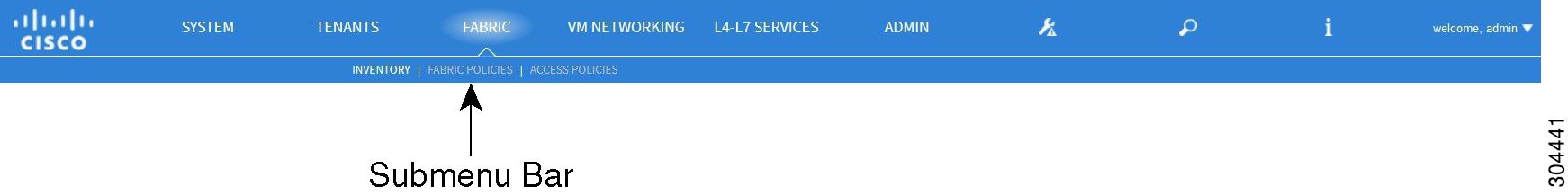
メニュー バーおよびサブメニュー バー
メニュー バーおよびサブメニュー バーには次の項目があります。
- [SYSTEM] タブ
- [TENANTS] タブ
- [FABRIC] タブ
- [VM NETWORKING] タブ
- [L4-L7 SERVICES] タブ
- [ADMIN] タブ
- [Search] アイコン
- [Navigation] ペイン
- [Work] ペイン
[SYSTEM] タブ
システム全体の状態のサマリー、その履歴、およびシステムレベルの障害のテーブルを収集および表示するには、[SYSTEM] タブを使用します。
[TENANTS] タブ
テナント管理の実行にメニュー バーの [TENANTS] タブを使用します。 サブメニュー バーに、[Add Tenant] リンクと、すべてのテナントを含むドロップダウン リストが表示されます。 最大 5 つまでの最近使用されたテナントもサブメニュー バーに表示されます。
-
テナントには、承認されたユーザのドメインベースのアクセス コントロールをイネーブルにするポリシーが含まれます。 承認されたユーザは、テナント管理やネットワーキング管理などの権限にアクセスできます。
-
ユーザは、ドメイン内のポリシーにアクセスしたりポリシーを設定するには読み取り/書き込み権限が必要です。 テナント ユーザは、1 つ以上のドメインに特定の権限を持つことができます。
-
マルチテナント環境では、リソースがそれぞれ分離されるように、テナントによりグループ ユーザのアクセス権限が提供されます(エンドポイント グループやネットワーキングなどのため)。 これらの権限では、異なるユーザが異なるテナントを管理することもできます。
[FABRIC] タブ
[VM NETWORKING] タブ
仮想マシン(VM)のさまざまな管理システムのインベントリを表示および設定するには、[VM NETWORKING] タブを使用します。 個別の管理システムへの接続(VMware vCenter または VMware vShield など)を設定できるさまざまな管理ドメインを設定し作成できます。 これらの VM 管理システム(API のコントローラとも呼ばれます)によって管理されるハイパーバイザおよび VM を表示するには、サブメニュー バーの [INVENTORY] タブを使用します。
[L4-L7 SERVICES] タブ
レイヤ 4 ~ レイヤ 7 デバイスを定義するパッケージのインポートなどのサービスを実行するには、[L4-L7 SERVICES] タブを使用します。 [INVENTORY] サブメニュー タブで既存のサービス ノードを確認できます。
[ADMIN] タブ
認証、認可、アカウンティングなどの管理機能、ポリシーのスケジューリング、レコードの保持と消去、ファームウェアのアップグレード、および syslog、Call Home、SNMP などの制御機能を実行するには、[ADMIN] タブを使用します。
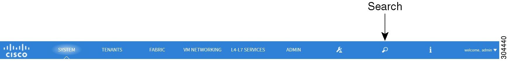
[Search] アイコン
検索フィールドを表示するには、[Search] アイコンをクリックします。 検索フィールドでは、名前またはその他の固有フィールドによってオブジェクトを検索できます。
[Navigation] ペイン
サブメニュー カテゴリのすべての要素に移動するには、APIC GUI の左側、サブメニュー バーのすぐ下の [Navigation] ペインを使用します。 [Navigation] ペインでコンポーネントを選択すると、そのオブジェクトが [Work] ペインに表示されます。
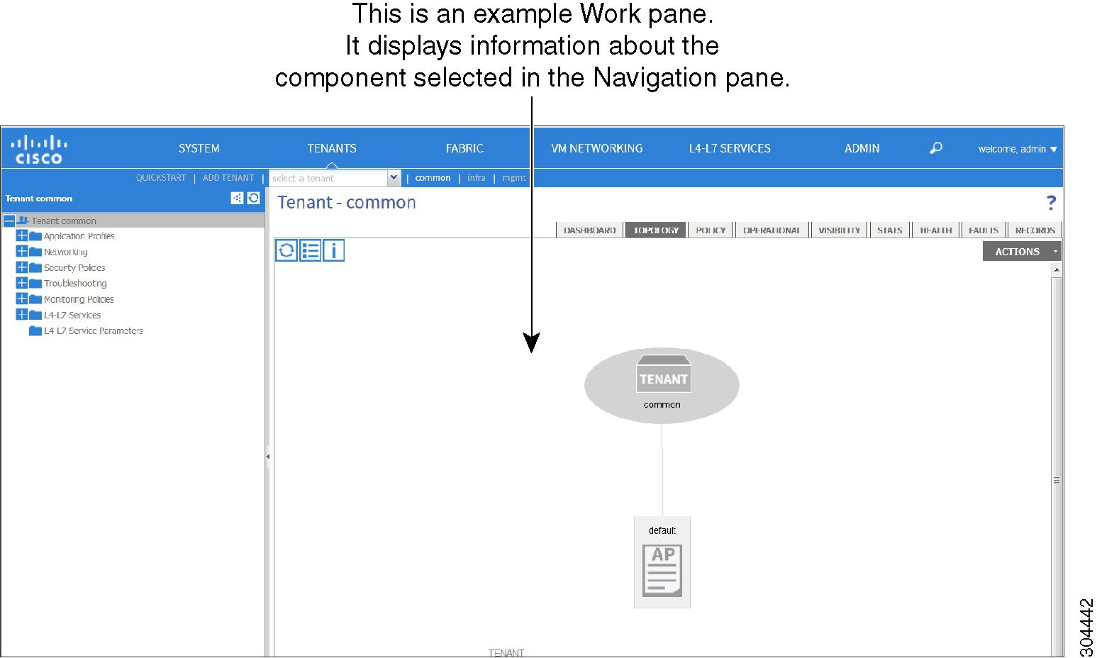
[Work] ペイン
APIC GUI の右側にある [Work] ペインに、[Navigation] ペインで選択したコンポーネントに関する詳細が表示されます。 [Work] ペインの表示例については、次の図を参照してください。
[Work] ペインは、次の要素で構成されます。
-
タブが表示されるコンテンツ領域。 これらのタブを使用すると、[Navigation] ペインで選択したコンポーネントに関連する情報にアクセスできます。 コンテンツ領域に表示されるタブは、選択されたコンポーネントにより異なります。
-
右上隅にある疑問符のアイコンで表示されている状況依存オンライン ヘルプへのリンク。
GUI アイコン
| アイコン | 説明 |
|---|---|
|
|
[Navigation] ペインの表示のコントロール矢印 |
|
|
[Work] ペインの最下部のコンテキスト ヘルプを表示または非表示にします |
|
|
テーブルを XML ファイルとしてダウンロードします |
|
|
[Navigation] ペインで選択したコンポーネントのグラフィック ビューが表示されます |
| |
[Navigation] ペインで選択したコンポーネントのグラフィック ビューが表示されます |
|
|
パネルの状況を更新します。 リポジトリが変わるたびにデータが更新されるため、接続の問題がある場合にのみ、このアイコンをクリックします |
| |
オンライン ヘルプ情報を表示します |
| |
設定 |
|
|
次のビュー |
|
|
前のビュー |
|
|
パスを表示します |
|
|
パスをクリアします |
エラー、統計情報およびヘルス レベルのアイコン
| アイコン | 説明 |
|---|---|
|
|
クリティカル:このアイコンは、重大度がクリティカルであるエラー レベルを示します。 |
|
|
メジャー:このアイコンは、重大度がメジャーであるエラー レベルを示します。 |
|
|
マイナー:このアイコンは、重大度がマイナーであるエラー レベルを示します。 |
|
|
警告:このアイコンは、警告を必要とするエラー レベルを示します。 |
APIC の例について
このマニュアルの例の手順にはパラメータ名が含まれます。 これらのパラメータ名は、例を容易に理解できるように記述されたもので、それらの使用は必須ではありません。
ファブリックの初期設定について
APIC によって管理するスイッチを追加し、GUI、CLI、または API を使用して手順を検証することによってファブリックを構築できます。
 (注) |
ファブリックを構築するには、事前にアウトオブバンド ネットワーク経由で APIC クラスタを作成しておく必要があります。 |
トポロジの例
トポロジ例は次のとおりです。
次の図は、ファブリック トポロジの例を示します。
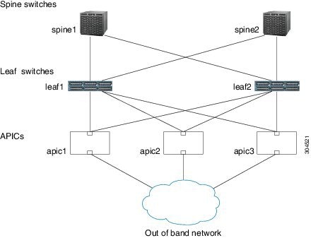
トポロジの接続の例
トポロジの接続の例の詳細は次のとおりです。
| 名前 | Connection Details |
|---|---|
| leaf1 |
eth1/1 = apic1(eth2/1) eth1/2 = apic2(eth2/1) eth1/3 = apic3(eth2/1) eth1/49 = spine1(eth5/1) eth1/50 = spine2(eth5/2) |
| leaf2 |
eth1/1 = apic1(eth2/2) eth1/2 = apic2(eth2/2) eth1/3 = apic3(eth2/2) eth1/49 = spine1(eth5/1) eth1/50 = spine2(eth5/2) |
| spine1 |
eth5/1 = leaf1(eth1/49) eth5/2 = leaf2(eth1/50) |
| spine2 |
eth5/1 = leaf2(eth1/49) eth5/2 = leaf1(eth1/50) |
APIC によるスイッチの検出
APIC は、ACI ファブリックに含まれるすべてのスイッチに対する自動プロビジョニングおよび管理の中心となるポイントです。 単一のデータセンターには複数のファブリック ACI がある場合があります。各データセンターには、独自の APIC クラスタとファブリックを構成する Cisco Nexus 9000 スイッチ シリーズがある場合があります。 スイッチが単一の APIC クラスタだけで管理されることを保証するには、各スイッチをファブリックを管理するその特定の APIC クラスタに登録する必要があります。
APIC は現在管理している任意のスイッチに直接接続された新規スイッチを検出します。 クラスタの各 APIC インスタンスは、最初に直接接続されたリーフ スイッチだけを検出します。 リーフ スイッチが APIC に登録されると、APIC はリーフ スイッチに直接接続されているすべてのスパイン スイッチを検出します。 各スパイン スイッチが登録されるごとに、APIC はそのスパイン スイッチに接続されているすべてのリーフ スイッチを検出します。 この段階的な検出方法により、APIC は簡単な手順でファブリック全体のトポロジを検出できます。
APIC クラスタへのスイッチの登録
(注) |
スイッチの登録を開始する前に、ファブリック内のすべてのスイッチが物理的に接続され、必要な設定で起動されていることを確認します。 APIC を使用してスイッチを登録する際には「GUI を使用した未接続スイッチの登録」を参照してください。 シャーシの設置については、http://www.cisco.com/en/US/products/ps13386/prod_installation_guides_list.htmlを参照してください。 |
スイッチが APIC に登録されると、そのスイッチは、APIC 管理対象のファブリック インベントリの一部になります。 アプリケーション セントリック インフラストラクチャ ファブリック(ACI ファブリック)の場合、APIC はインフラストラクチャのスイッチのプロビジョニング、管理、および監視を一元化します。
(注) |
インフラストラクチャの IP アドレス範囲は、インバンドおよびアウトオブバンドのネットワーク用の ACI ファブリックで使用する他の IP アドレスと重複してはなりません。 |
APIC によるスイッチ検出の検証およびスイッチ管理
スイッチが APIC に登録された後、APIC は自動的にファブリック トポロジを認識し、ネットワーク全体を把握してファブリック トポロジ内のすべてのスイッチを管理します。
個々のスイッチにアクセスすることなく、APIC から各スイッチの設定、監視、およびアップグレードができます。
ファブリック トポロジの検証
すべてのスイッチが APIC クラスタに登録された後、APIC は自動的にファブリックのすべてのリンクおよび接続を検出し、その結果、トポロジ全体を検出します。
VM 管理のアンマネージド スイッチの接続
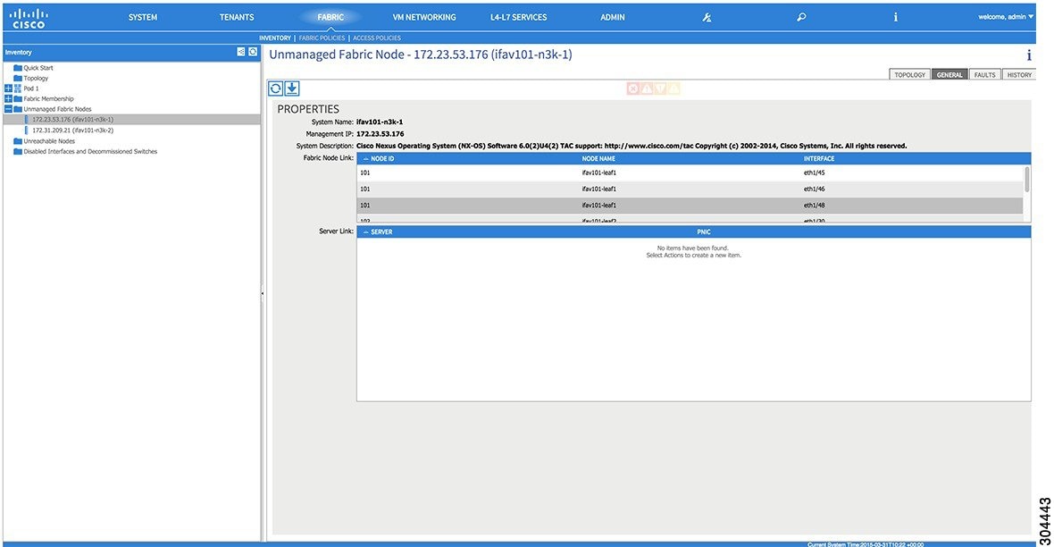
GUI を使用した未接続スイッチの登録
(注) |
インフラストラクチャの IP アドレス範囲は、インバンドおよびアウトオブバンドのネットワーク用の ACI ファブリックで使用する他の IP アドレスと重複してはなりません。 |
(注) |
このタスク例のビデオを視聴するには、Videos Webpage を参照してください。 |
ファブリック内のすべてのスイッチが物理的に接続され、起動されていることを確認します。
| ステップ 1 | メニュー バーで、 を選択します。 |
| ステップ 2 | [Navigation] ペインで、適切なポッドを選択してポッドを展開し、[Fabric Membership] をクリックします。 [Work] ペインで、[Fabric Membership] テーブルに、単一の リーフ スイッチ が ID 0 とともに表示されます。 apic1 に接続されている リーフ スイッチ です。 |
| ステップ 3 |
リーフ スイッチ の行をダブルクリックし、次の操作を実行して ID を設定します。
|
| ステップ 4 | 1 つ以上の スパイン スイッチ が表示されるまで [Work] ペインを監視します。 |
| ステップ 5 |
スパイン スイッチ の行をダブルクリックして ID を設定し、次の操作を実行します。
|
| ステップ 6 | [Fabric Membership] テーブルに表示されているスイッチごとに次の手順を実行します。 |
REST API を使用した未接続スイッチの登録
(注) |
インフラストラクチャの IP アドレス範囲は、インバンドおよびアウトオブバンドのネットワーク用の ACI ファブリックで使用する他の IP アドレスと重複してはなりません。 |
|
例: POST: https://apic_ip_address/api/node/mo/uni/controller.xml <fabricNodeIdentPol> <fabricNodeIdentP serial="FGE173900ZD" name="leaf1" nodeId="101"/> <fabricNodeIdentP serial="FGE1740010A" name="leaf2" nodeId="102"/> <fabricNodeIdentP serial="FGE1740010H" name="spine1" nodeId="103"/> <fabricNodeIdentP serial="FGE1740011B" name="spine2" nodeId="104"/> </fabricNodeIdentPol> |
CLI を使用した未接続スイッチの登録
(注) |
インフラストラクチャの IP アドレス範囲は、インバンドおよびアウトオブバンドのネットワーク用の ACI ファブリックで使用する他の IP アドレスと重複してはなりません。 |
| ステップ 1 |
CLI で、ディレクトリを /aci に変更します。 例: admin@apic1:~> cd /aci |
| ステップ 2 |
スイッチを登録します。 例: admin@apic1:fabric-membership> cd /aci/fabric/inventory/fabric-membership/node-policies admin@apic1:node-policies mocreate FGE173900ZD id 101 name leaf1 admin@apic1:node-policies moconfig commit |
| ステップ 3 | 他のスイッチに対して上記の手順を繰り返します(スイッチ 102、103、104 など)。 |
GUI を使用した接続済みスイッチの登録
(注) |
このタスク例のビデオを視聴するには、Videos Webpage を参照してください。 |
| ステップ 1 | メニュー バーで、 を選択します。 |
| ステップ 2 | [Navigation] ペインで、[Pod 1] の下の [Fabric Membership] を展開します。 ファブリック内のスイッチは、ノード ID とともに表示されます。 [Work] ペインに、登録されているすべてのスイッチが、割り当てられた IP アドレスとともに表示されます。 |
REST API を使用した接続済みスイッチの登録
|
例: GET: https://<apic-ip>/api/node/class/topSystem.xml?
<?xml version="1.0" encoding="UTF-8"?>
<imdata>
<topSystem address="10.0.0.1" dn="topology/pod-1/node-1/sys" fabricId="1" id="1" name="apic1"
oobMgmtAddr="10.30.13.44" podId="1" role="apic" serial="" state="in-service" systemUpTime="00:00:00:02.199" .../>
<topSystem address="10.0.0.2" dn="topology/pod-1/node-2/sys" fabricId="1" id="2" name="apic2"
oobMgmtAddr="10.30.13.45" podId="1" role="apic" serial="" state="in-service" systemUpTime="00:00:00:02.199" .../>
<topSystem address="10.0.0.3" dn="topology/pod-1/node-3/sys" fabricId="1" id="3" name="apic3"
oobMgmtAddr="10.30.13.46" podId="1" role="apic" serial="" state="in-service" systemUpTime="00:00:00:02.199" .../>
<topSystem address="10.0.98.127" dn="topology/pod-1/node-101/sys" fabricId="1" id="101"
name="leaf1" oobMgmtAddr="0.0.0.0" podId="1" role="leaf" serial="FOX-270308" state="in-service"
systemUpTime="00:00:00:02.199" .../>
<topSystem address="10.0.98.124" dn="topology/pod-1/node-102/sys" fabricId="1" id="102"
name="leaf2" oobMgmtAddr="0.0.0.0" podId="1" role="leaf" serial="FOX-270308" state="in-service"
systemUpTime="00:00:00:02.199" .../>
<topSystem address="10.0.98.125" dn="topology/pod-1/node-103/sys" fabricId="1" id="103"
name="spine2" oobMgmtAddr="0.0.0.0" podId="1" role="spine" serial="FOX-616689" state="in-service"
systemUpTime="00:00:00:02.199" .../>
<topSystem address="10.0.98.126" dn="topology/pod-1/node-104/sys" fabricId="1" id="104"
name="spine1" oobMgmtAddr="0.0.0.0" podId="1" role="spine" serial="FOX-616689" state="in-service"
systemUpTime="00:00:00:02.199" .../>
</imdata>
|
CLI を使用した接続済みスイッチの登録
| ステップ 1 |
CLI で、ディレクトリを /aci に変更します。 例: admin@apic1:~> cd /aci |
| ステップ 2 |
スイッチの登録を検証します。 例: admin@apic1:pod-1> cat node-101/summary id : 101 name : leaf1 tags : topology/pod-1/node-101 admin-state : on alias : model : N9K-C9396TX vendor : Cisco Systems, Inc revision : 0.1.6 serial : FGE173900ZD up-time : 00:07:50:32.000 infra-ip : 10.0.36.95 in-band-management-ip : 0.0.0.0 out-of-band-management-ip : 0.0.0.0 top-system-name : leaf1 type : leaf health-score : topology/pod-1/node-101/sys firmware : simsw-1.0(0.552) |
GUI を使用したファブリック トポロジの検証
(注) |
このタスク例のビデオを視聴するには、Videos Webpage を参照してください。 |
| ステップ 1 | メニュー バーで、 を選択します。 |
| ステップ 2 | [Navigation] ペインで、表示したいポッドを選択します。 |
| ステップ 3 | [Work] ペインで、[TOPOLOGY] タブをクリックします。 表示される図には、すべての接続されたスイッチ、APIC インスタンス、およびリンクが示されます。 |
| ステップ 4 |
(任意) リーフ スイッチ または スパイン スイッチ のポート レベルでの接続を表示するには、トポロジ図の当該アイコンをダブルクリックします。 トポロジ図に戻るには、[Work] ペインの左上隅にある [Previous View] アイコンをクリックします。 |
| ステップ 5 | (任意) トポロジ図を更新するには、[Work] ペインの左上隅にある [Refresh] アイコンをクリックします。 |
REST API を使用したファブリック トポロジの検証
|
例: ユーザ参照用の識別子は次のとおりです。
GET: https://<apic-ip>/api/node/class/fabricLink.xml?

<?xml version="1.0" encoding="UTF-8"?>
<imdata>
    <fabricLink dn="topology/lnkcnt-19/lnk-18-1-50-to-19-5-2" n1="18" n2="19" p1="50" p2="2" s1="1" s2="5" status="" .../>
    <fabricLink dn="topology/lnkcnt-20/lnk-18-1-49-to-20-5-1" n1="18" n2="20" p1="49" p2="1" s1="1" s2="5" status="" .../>
    <fabricLink dn="topology/lnkcnt-3/lnk-18-1-1-to-3-1-1" n1="18" n2="3" p1="1" p2="1" s1="1" s2="1" status="" .../>
    <fabricLink dn="topology/lnkcnt-19/lnk-17-1-49-to-19-5-1" n1="17" n2="19" p1="49" p2="1" s1="1" s2="5" status="" .../>
    <fabricLink dn="topology/lnkcnt-20/lnk-17-1-50-to-20-5-2" n1="17" n2="20" p1="50" p2="2" s1="1" s2="5" status="" .../>
    <fabricLink dn="topology/lnkcnt-1/lnk-17-1-1-to-1-1-1" n1="17" n2="1" p1="1" p2="1" s1="1" s2="1" status="" .../>
    <fabricLink dn="topology/lnkcnt-2/lnk-17-1-2-to-2-1-1" n1="17" n2="2" p1="2" p2="1" s1="1" s2="1" status="" .../>
</imdata>
|
ローカル ユーザの設定
初期設定スクリプトで、管理者アカウントが設定され、システムの起動時には admin が唯一のユーザです。 APIC は、きめ細かなロール ベースのアクセス制御システムをサポートしており、権限の少ない非管理者ユーザなど、さまざまなロールのユーザ アカウントを作成できます。
リモート ユーザの設定
ローカル ユーザを設定する代わりに、一元化された企業クレデンシャルのデータセンターの APIC を指定できます。 APIC は Lightweight Directory Access Protocol(LDAP)、Active Directory、RADIUS および TACACS+ をサポートしています。
外部認証プロバイダーを通じて認証されたリモート ユーザを設定するには、次の前提条件を満たす必要があります。
GUI を使用したローカル ユーザの設定
(注) |
このタスク例のビデオを視聴するには、Videos Webpage を参照してください。 |
| ステップ 1 | メニュー バーで、 を選択します。 |
| ステップ 2 | [Navigation] ペインで、[AAA Authentication] をクリックします。 |
| ステップ 3 | [Work] ペインで、デフォルトの [Authentication] フィールドの [Relam] フィールドに Local と表示されていることを確認します。 |
| ステップ 4 |
[Navigation] ペインで、 を展開します。 admin ユーザはデフォルトで存在します。 |
| ステップ 5 | [Navigation] ペインで、[Create Local User] を右クリックします。 |
| ステップ 6 | [Security] ダイアログボックスで、ユーザに必要なセキュリティ ドメインを選択し、[Next] をクリックします。 |
| ステップ 7 |
[Roles] ダイアログボックスで、オプション ボタンをクリックしてユーザのロールを選択し、[Next] をクリックします。 読み取り専用、または読み取り/書き込み権限を付与できます。 |
| ステップ 8 | [User Identity] ダイアログボックスで、次の操作を実行します。 |
| ステップ 9 | [Navigation] ペインで、作成したユーザの名前をクリックします。 [Work] ペインで、[Security Domains] エリア内のそのユーザの横の [+] 記号を展開します。 ユーザのアクセス権限が表示されます。 |
REST API を使用したローカル ユーザの設定
|
例: URL: https://<apic-ip>/api/policymgr/mo/uni/userext.xml
POST CONTENT:
<aaaUser name="operations" phone="" pwd="test!123" >
<aaaUserDomain childAction="" descr="" name="all" rn="userdomain-all" status="">
<aaaUserRole childAction="" descr="" name="Ops" privType="writePriv"/>
</aaaUserDomain>
</aaaUser>
|
CLI を使用したローカル ユーザの設定
| ステップ 1 |
CLI で、ディレクトリを /aci に変更します。 例: admin@apic1:~> cd /aci |
| ステップ 2 |
ローカル ユーザを作成します。 例: admin@apic1:aci> cd admin/aaa/security-management/ admin@apic1:security-management> cd local-users/ admin@apic1:local-users> mocreate operations admin@apic1:local-users> moconfig commit Committed mo 'admin/aaa/security-management/local-users/operations' All mos committed successfully. admin@apic1:local-users> cd operations/ admin@apic1:operations> moset password Password: Verify: password is set and committed. admin@apic1:operations> moconfig commit admin@apic1:operations> |
外部認証サーバの AV ペア
既存のユーザ レコードに Cisco 属性/値(AV)ペアを追加して、APIC コントローラにユーザ権限を伝播することができます。 Cisco AV ペアは、APIC ユーザに対してロールベース アクセス コントロール(RBAC)のロールと権限を指定するために使用する単一の文字列です。 オープン RADIUS サーバ(/etc/raddb/users)の設定例を次に示します。
aaa-network-admin Cleartext-Password := "<password>"
Cisco-avpair = "shell:domains = all/aaa/read-all(16001)"
外部認証サーバの AV ペアの設定
属性/値(AV)ペア文字列のカッコ内の数値は、セキュア シェル(SSH)または Telnet を使用してログインしたユーザの UNIX ユーザ ID として使用されます。
|
例: * shell:domains = domainA/writeRole1|writeRole2|writeRole3/readRole1|readRole2,domainB/writeRole1|writeRole2|writeRole3/readRole1|readRole2
* shell:domains = domainA/writeRole1|writeRole2|writeRole3/readRole1|readRole2,domainB/writeRole1|writeRole2|writeRole3/readRole1|readRole2(8101)
These are the boost regexes supported by APIC:
uid_regex("shell:domains\\s*[=:]\\s*((\\S+?/\\S*?/\\S*?)(,\\S+?/\\S*?/\\S*?){0,31})(\\(\\d+\\))$");
regex("shell:domains\\s*[=:]\\s*((\\S+?/\\S*?/\\S*?)(,\\S+?/\\S*?/\\S*?){0,31})$");
次に、例を示します。 shell:domains = coke/tenant-admin/read-all,pepsi//read-all(16001) |
GUI を使用したリモート ユーザの設定
(注) |
このタスク例のビデオを視聴するには、Videos Webpage を参照してください。 |
| ステップ 1 | メニュー バーで、 を選択します。 [Navigation] ペインで、[RADIUS Management] を展開します。 |
| ステップ 2 | [RADIUS Providers] を右クリックし、[Create RADIUS Provider] をクリックします。 |
| ステップ 3 |
[Create RADIUS Provider] ダイアログボックスで、次の操作を実行します。
|
| ステップ 4 | [Navigation] ペインで、[RADIUS Providers] プロバイダーの下にある、作成した RADIUS プロバイダーをクリックします。 RADIUS プロバイダーの設定についての詳細は、[Work] ペインに表示されます。 |
REST API を使用したリモート ユーザの設定
| ステップ 1 |
RADIUS プロバイダーを作成します。 例: URL: https://<apic-ip>/api/policymgr/mo/uni/userext/radiusext.xml POST Content: <aaaRadiusProvider name="radius-auth-server.org.com" key="test123" /> |
| ステップ 2 |
ログイン ドメインを作成します。 例: URL: https://<apic-ip>/api/policymgr/mo/uni/userext.xml POST Content: <aaaLoginDomain name="rad"> <aaaDomainAuth realm="radius"/> </aaaLoginDomain> |
CLI を使用したリモート ユーザの設定
| ステップ 1 |
CLI で、ディレクトリを /aci に変更します。 例: admin@apic1:~> cd /aci |
| ステップ 2 |
RADIUS プロバイダーを作成します。 例: admin@apic1:aci> cd admin/aaa/radius-management/ admin@apic1:radius-management> cd radius-providers admin@apic1:radius-providers> mocreate radius-auth-server.org.com admin@apic1:radius-providers> moconfig commit Committed mo 'admin/aaa/radius-management/radius-providers/radius-auth-server.org.com |
| ステップ 3 |
RADIUS プロバイダーを確認します。 例: All mos committed successfully. admin@apic1:radius-providers> cd radius-auth-server.org.com/ admin@apic1:radius-auth-server.org.com> moset key Password: Verify: key is set and committed. admin@apic1:radius-auth-server.org.com> moconfig commit admin@apic1:radius-auth-server.org.com> pwd admin@apic1:radius-auth-server.org.com> cat summary host-name-or-ip-address : radius-auth-server.org.com description : authorization-port : 1812 authorization-protocol : pap key : timeout : 5 retries : 1 management-epg : admin@apic1:radius-auth-server.org.com> |
| ステップ 4 |
ログイン ドメインを作成します。 例: admin@apic1:aci> cd admin/aaa/authentication/login-domains/ admin@apic1:login-domains> mocreate rad admin@apic1:login-domains> cd rad/ admin@apic1:rad> moset realm radius admin@apic1:rad> moconfig commit Committed mo 'admin/aaa/authentication/login-domains/rad' |
| ステップ 5 |
ログイン ドメインを確認します。 例: admin@apic1:/aci/admin/aaa/authentication/login-domains/rad> cat summary # aaa.LoginDomain login-domain : ------------ name : rad description : realm : radius provider-group : |
管理アクセスの追加
次の方法のうちの 1 つで管理アクセスを設定できます。
-
インバンド管理アクセス:APIC および ACI ファブリックへのインバンド管理接続を設定できます。 最初に、APIC がリーフ スイッチと通信するときに APIC によって使用される VLAN を設定してから、VMM サーバがリーフ スイッチとの通信に使用する VLAN を設定します。
-
アウトオブバンド管理アクセス:APIC および ACI ファブリックへのアウトオブバンド管理接続を設定できます。 アウトオブバンド エンドポイント グループ(EPG)に関連付けられたアウトオブバンド コントラクトを設定し、外部ネットワーク プロファイルにそのコントラクトをアタッチします。
(注)
APIC アウトオブバンド管理接続のリンクは、1 Gbps である必要があります。
GUI を使用したインバンド管理アクセスの設定
(注) |
このタスク例のビデオを視聴するには、Videos Webpage を参照してください。 |
| ステップ 1 | メニュー バーで、 を選択します。 [Work] ペインで、[Configure an Interface, PC, and VPC] をクリックします。 |
| ステップ 2 | [Configure Interface, PC, and VPC] ダイアログボックスで、スイッチの図の横にある大きな [+] アイコンをクリックして、新しいプロファイルを作成し、APIC 用に VLAN を設定します。 |
| ステップ 3 | [Switches] フィールドで、ドロップダウン リスト内の、APIC が接続されているスイッチのチェックボックスをオンにします。 (leaf1 および leaf2)。 |
| ステップ 4 | [Switch Profile Name] フィールドに、プロファイル(apicConnectedLeaves)の名前を入力します。 |
| ステップ 5 | ポートを設定するには、[+] アイコンをクリックします。 |
| ステップ 6 | [Interface Type] 領域で、[Individual] オプション ボタンが選択されていることを確認します。 |
| ステップ 7 | [Interfaces] フィールドに、APIC が接続されているポートを入力します(1/1~3)。 |
| ステップ 8 | [Interface Selector Name] フィールドに、ポート プロファイルの名前(apicConnectedPorts)を入力します。 |
| ステップ 9 | [Interface Policy Group] フィールドで、ドロップダウン リストから、[Create Interface Policy Group] を選択します。 |
| ステップ 10 |
[Create Access Port Policy Group] ダイアログボックスで、次の操作を実行します。
|
| ステップ 11 |
[Create Attachable Access Entity Profile] ダイアログボックスで、次の操作を実行します。
|
| ステップ 12 |
VMM サーバ ポートに VLAN を設定するには、[Configured Switch Interfaces] 領域を展開して、次の操作を実行します。
|
| ステップ 13 | を選択します。 [Navigation] ペインで、インバンド接続のブリッジ ドメインを設定するために、 を展開します。 |
| ステップ 14 |
インバンド ブリッジ ドメイン(inb)を右クリックして、[Create Subnet] をクリックし、次の操作を実行します。
|
| ステップ 15 |
メニュー バーで、 を選択します。 [Navigation] ペインで、 を展開し、[In-Band EPG - default] をクリックして、インバンド接続の VLAN を設定するために、次の操作を実行します。
|
| ステップ 16 |
[Navigation] ペインで、[Node Management Addresses] を右クリックします。 [Create Node Management Addresses] をクリックして、ファブリック内の各種ノードに IP アドレスを設定するために次のアクションを実行します。
|
| ステップ 17 |
リーフ スイッチおよびスパイン スイッチの IP アドレスを設定します。
|
| ステップ 18 | [Navigation] ペインで、[Node Management Addresses] の下にある APIC のポリシー名(apicInb)をクリックして設定を確認します。 [Work] ペインに、各種ノードに割り当てられた IP アドレスが表示されます。 |
| ステップ 19 | [Navigation] ペインで、[Node Management Addresses] の下にあるスイッチのポリシー名(switchInb)をクリックします。 [Work] ペインに、スイッチに割り当てられた IP アドレス、およびスイッチが使用するゲートウェイ アドレスが表示されます。 |
REST API を使用したインバンド管理アクセスの設定
| ステップ 1 |
VLAN の名前空間を作成します。 例: <?xml version="1.0" encoding="UTF-8"?>
<!-- api/policymgr/mo/uni.xml -->
<polUni>
<infraInfra>
<!-- Static VLAN range -->
<fvnsVlanInstP name="inband" allocMode="static">
<fvnsEncapBlk name="encap" from="vlan-10" to="vlan-11"/>
</fvnsVlanInstP>
</infraInfra>
</polUni>
|
| ステップ 2 |
物理的ドメインを作成します。 例: <?xml version="1.0" encoding="UTF-8"?>
<!-- api/policymgr/mo/uni.xml -->
<polUni>
<physDomP name="inband">
<infraRsVlanNs tDn="uni/infra/vlanns-inband-static"/>
</physDomP>
</polUni>
|
| ステップ 3 |
インバンド管理用のセレクタを作成します。 例: <?xml version="1.0" encoding="UTF-8"?>
<!-- api/policymgr/mo/.xml -->
<polUni>
<infraInfra>
<infraNodeP name="vmmNodes">
<infraLeafS name="leafS" type="range">
<infraNodeBlk name="single0" from_="101" to_="101"/>
</infraLeafS>
<infraRsAccPortP tDn="uni/infra/accportprof-vmmPorts"/>
</infraNodeP>
<!-- Assumption is that VMM host is reachable via eth1/40. -->
<infraAccPortP name="vmmPorts">
<infraHPortS name="portS" type="range">
<infraPortBlk name="block1"
fromCard="1" toCard="1"
fromPort="40" toPort="40"/>
<infraRsAccBaseGrp tDn="uni/infra/funcprof/accportgrp-inband" />
</infraHPortS>
</infraAccPortP>
<infraNodeP name="apicConnectedNodes">
<infraLeafS name="leafS" type="range">
<infraNodeBlk name="single0" from_="101" to_="102"/>
</infraLeafS>
<infraRsAccPortP tDn="uni/infra/accportprof-apicConnectedPorts"/>
</infraNodeP>
<!-- Assumption is that APIC is connected to eth1/1. -->
<infraAccPortP name="apicConnectedPorts">
<infraHPortS name="portS" type="range">
<infraPortBlk name="block1"
fromCard="1" toCard="1"
fromPort="1" toPort="3"/>
<infraRsAccBaseGrp tDn="uni/infra/funcprof/accportgrp-inband" />
</infraHPortS>
</infraAccPortP>
<infraFuncP>
<infraAccPortGrp name="inband">
<infraRsAttEntP tDn="uni/infra/attentp-inband"/>
</infraAccPortGrp>
</infraFuncP>
<infraAttEntityP name="inband">
<infraRsDomP tDn="uni/phys-inband"/>
</infraAttEntityP>
</infraInfra>
</polUni>
|
| ステップ 4 |
インバンド ブリッジ ドメインとエンドポイント グループ(EPG)を設定します。 例: <?xml version="1.0" encoding="UTF-8"?>
<!-- api/policymgr/mo/.xml -->
<polUni>
<fvTenant name="mgmt">
<!-- Configure the in-band management gateway address on the
in-band BD. -->
<fvBD name="inb">
<fvSubnet ip="10.13.1.254/24"/>
</fvBD>
<mgmtMgmtP name="default">
<!-- Configure the encap on which APICs will communicate on the
in-band network. -->
<mgmtInB name="default" encap="vlan-10">
<fvRsProv tnVzBrCPName="default"/>
</mgmtInB>
</mgmtMgmtP>
</fvTenant>
</polUni>
|
| ステップ 5 |
アドレス プールを作成します。 例: <?xml version="1.0" encoding="UTF-8"?>
<!-- api/policymgr/mo/.xml -->
<polUni>
<fvTenant name="mgmt">
<!-- Adresses for APIC in-band management network -->
<fvnsAddrInst name="apicInb" addr="10.13.1.254/24">
<fvnsUcastAddrBlk from="10.13.1.1" to="10.13.1.10"/>
</fvnsAddrInst>
<!-- Adresses for switch in-band management network -->
<fvnsAddrInst name="switchInb" addr="10.13.1.254/24">
<fvnsUcastAddrBlk from="10.13.1.101" to="10.13.1.120"/>
</fvnsAddrInst>
</fvTenant>
</polUni>
|
| ステップ 6 |
管理グループを作成します。 例: <?xml version="1.0" encoding="UTF-8"?>
<!-- api/policymgr/mo/.xml -->
<polUni>
<infraInfra>
<!-- Management node group for APICs -->
<mgmtNodeGrp name="apic">
<infraNodeBlk name="all" from_="1" to_="3"/>
<mgmtRsGrp tDn="uni/infra/funcprof/grp-apic"/>
</mgmtNodeGrp>
<!-- Management node group for switches-->
<mgmtNodeGrp name="switch">
<infraNodeBlk name="all" from_="101" to_="104"/>
<mgmtRsGrp tDn="uni/infra/funcprof/grp-switch"/>
</mgmtNodeGrp>
<!-- Functional profile -->
<infraFuncP>
<!-- Management group for APICs -->
<mgmtGrp name="apic">
<!-- In-band management zone -->
<mgmtInBZone name="default">
<mgmtRsInbEpg tDn="uni/tn-mgmt/mgmtp-default/inb-default"/>
<mgmtRsAddrInst tDn="uni/tn-mgmt/addrinst-apicInb"/>
</mgmtInBZone>
</mgmtGrp>
<!-- Management group for switches -->
<mgmtGrp name="switch">
<!-- In-band management zone -->
<mgmtInBZone name="default">
<mgmtRsInbEpg tDn="uni/tn-mgmt/mgmtp-default/inb-default"/>
<mgmtRsAddrInst tDn="uni/tn-mgmt/addrinst-switchInb"/>
</mgmtInBZone>
</mgmtGrp>
</infraFuncP>
</infraInfra>
</polUni>
|
CLI を使用したインバンド管理アクセスの設定
| ステップ 1 |
管理トラフィック用の VLAN の名前空間を作成します。 例: admin@apic1:~> cd /aci/fabric/access-policies/pools/vlan/ admin@apic1:vlan> mocreate inband static-allocation admin@apic1:vlan> moconfig commit Committing mo 'fabric/access-policies/pools/vlan/inband-static-allocation' All mos committed successfully. admin@apic1:vlan> cd inband-static-allocation/encap-blocks admin@apic1:encap-blocks> mocreate vlan10 vlan11 admin@apic1:encap-blocks> cd vlan10-vlan11 admin@apic1:vlan10-vlan11> moset name encap admin@apic1:vlan10-vlan11> moconfig commit Committing mo 'fabric/access-policies/pools/vlan/inband-static-allocation/encap-blocks/vlan10-vlan11' All mos committed successfully. admin@apic1:vlan10-vlan11> |
| ステップ 2 |
管理トラフィック用の物理ドメインを作成します。 例: admin@apic1:~> cd /aci/fabric/access-policies/physical-and-external-domains/physical-domains/ admin@apic1:physical-domains> mocreate inband admin@apic1:physical-domains> moconfig commit Committing mo 'fabric/access-policies/physical-and-external-domains/physical-domains/inband' All mos committed successfully. admin@apic1:physical-domains> cd inband admin@apic1:inband> moset vlan-pools fabric/access-policies/pools/vlan/inband-static-allocation admin@apic1:inband> moconfig commit Committing mo 'fabric/access-policies/physical-and-external-domains/physical-domains/inband' All mos committed successfully. admin@apic1:inband> |
| ステップ 3 |
インバンド トラフィック用のリーフ セレクタを作成します。 例: admin@apic1:~> cd /aci/fabric/access-policies/switch-policies/profiles admin@apic1:profiles> mocreate vmmNodes admin@apic1:profiles> moconfig commit Committing mo 'fabric/access-policies/switch-policies/profiles/vmmNodes' All mos committed successfully. admin@apic1:profiles> cd vmmNodes admin@apic1:vmmNodes> mocreate leaf-selector leafS range admin@apic1:vmmNodes> moconfig commit Committing mo 'fabric/access-policies/switch-policies/profiles/vmmNodes/leaf-selector-leafS-range' All mos committed successfully. admin@apic1:vmmNodes> admin@apic1:vmmNodes> cd leaf-selector-leafS-range admin@apic1:leaf-selector-leafS-range> mocreate single0 admin@apic1:leaf-selector-leafS-range> cd single0 admin@apic1:single0> moset to 101 admin@apic1:single0> moset from 101 admin@apic1:single0> moconfig commit Committing mo 'fabric/access-policies/switch-policies/profiles/vmmNodes/leaf-selector-leafS-range/single0' All mos committed successfully. admin@apic1:single0> admin@apic1:single0> cd ../../associated-interface-selector-profiles admin@apic1:associated-interface-selector-profiles> mocreate fabric/access-policies/interface-policies/profiles/interfaces/vmmPorts admin@apic1:associated-interface-selector-profiles> moconfig commit Committing mo 'fabric/access-policies/switch-policies/profiles/vmmNodes/associated-interface-selector-profiles/[fabric/access-policies /interface-policies/profiles/interfaces/vmmPorts]' All mos committed successfully. admin@apic1:associated-interface-selector-profiles> admin@apic1:associated-interface-selector-profiles> cd /aci/fabric/access-policies/interface-policies/profiles/interfaces admin@apic1:interfaces> mocreate vmmPorts admin@apic1:interfaces> moconfig commit Committing mo 'fabric/access-policies/interface-policies/profiles/interfaces/vmmPorts' All mos committed successfully. admin@apic1:interfaces> cd vmmPorts admin@apic1:vmmPorts> mocreate portS range admin@apic1:vmmPorts> moconfig commit Committing mo 'fabric/access-policies/interface-policies/profiles/interfaces/vmmPorts/portS-range' All mos committed successfully. admin@apic1:vmmPorts> admin@apic1:vmmPorts> cd portS-range admin@apic1:portS-range> mocreate block1 admin@apic1:portS-range> cd block1 admin@apic1:block1> moset from-module 1 admin@apic1:block1> moset to-module 1 admin@apic1:block1> moset from-port 40 admin@apic1:block1> moset to-port 40 admin@apic1:block1> moconfig commit Committing mo 'fabric/access-policies/interface-policies/profiles/interfaces/vmmPorts/portS-range/block1' All mos committed successfully. admin@apic1:block1> admin@apic1:block1> cd ../ admin@apic1:portS-range> moset policy-group fabric/access-policies/interface-policies/policy-groups/interface/inband admin@apic1:portS-range> moconfig commit Committing mo 'fabric/access-policies/interface-policies/profiles/interfaces/vmmPorts/portS-range' All mos committed successfully. admin@apic1:portS-range> admin@apic1:portS-range> cd /aci/fabric/access-policies/switch-policies/profiles admin@apic1:profiles> mocreate apicConnectedNodes admin@apic1:profiles> moconfig commit Committing mo 'fabric/access-policies/switch-policies/profiles/apicConnectedNodes' All mos committed successfully. admin@apic1:profiles> cd apicConnectedNodes admin@apic1:apicConnectedNodes> mocreate leaf-selector leafS range admin@apic1:apicConnectedNodes> moconfig commit Committing mo 'fabric/access-policies/switch-policies/profiles/apicConnectedNodes/leaf-selector-leafS-range' All mos committed successfully. admin@apic1:apicConnectedNodes> admin@apic1:apicConnectedNodes> cd leaf-selector-leafS-range admin@apic1:leaf-selector-leafS-range> mocreate single0 admin@apic1:leaf-selector-leafS-range> cd single0 admin@apic1:single0> moset to 102 admin@apic1:single0> moset from 101 admin@apic1:single0> moconfig commit Committing mo 'fabric/access-policies/switch-policies/profiles/apicConnectedNodes/leaf-selector-leafS-range/single0' All mos committed successfully. admin@apic1:single0> admin@apic1:single0> cd ../../associated-interface-selector-profiles admin@apic1:associated-interface-selector-profiles> mocreate fabric/access-policies/interface-policies/profiles/interfaces /apicConnectedPorts admin@apic1:associated-interface-selector-profiles> moconfig commit Committing mo 'fabric/access-policies/switch-policies/profiles/apicConnectedNodes/associated-interface-selector-profiles/[fabric/access-policies /interface-policies/profiles/interfaces/apicConnectedPorts]' All mos committed successfully. admin@apic1:associated-interface-selector-profiles> admin@apic1:associated-interface-selector-profiles> cd /aci/fabric/access-policies/interface-policies/profiles/interfaces admin@apic1:interfaces> mocreate apicConnectedPorts admin@apic1:interfaces> moconfig commit Committing mo 'fabric/access-policies/interface-policies/profiles/interfaces/apicConnectedPorts' All mos committed successfully. admin@apic1:interfaces> cd apicConnectedPorts admin@apic1:apicConnectedPorts> mocreate portS range admin@apic1:apicConnectedPorts> moconfig commit Committing mo 'fabric/access-policies/interface-policies/profiles/interfaces/apicConnectedPorts/portS-range' All mos committed successfully. admin@apic1:apicConnectedPorts> admin@apic1:apicConnectedPorts> cd portS-range admin@apic1:portS-range> mocreate block1 admin@apic1:portS-range> cd block1 admin@apic1:block1> moset from-module 1 admin@apic1:block1> moset to-module 1 admin@apic1:block1> moset from-port 1 admin@apic1:block1> moset to-port 3 admin@apic1:block1> moconfig commit Committing mo 'fabric/access-policies/interface-policies/profiles/interfaces/apicConnectedPorts/portS-range/block1' All mos committed successfully. admin@apic1:block1> cd ../ admin@apic1:portS-range> moset policy-group fabric/access-policies/interface-policies/policy-groups/interface/inband admin@apic1:portS-range> moconfig commit Committing mo 'fabric/access-policies/interface-policies/profiles/interfaces/apicConnectedPorts/portS-range' All mos committed successfully. admin@apic1:portS-range> admin@apic1:portS-range> cd /aci/fabric/access-policies/interface-policies/policy-groups/interface admin@apic1:interface> mocreate inband admin@apic1:interface> moconfig commit Committing mo 'fabric/access-policies/interface-policies/policy-groups/interface/inband' All mos committed successfully. admin@apic1:interface> cd inband admin@apic1:inband> moset attached-entity-profile fabric/access-policies/global-policies/attachable-entity-profile/inband admin@apic1:inband> moconfig commit Committing mo 'fabric/access-policies/interface-policies/policy-groups/interface/inband' All mos committed successfully. admin@apic1:inband> admin@apic1:inband> cd /aci/fabric/access-policies/global-policies/attachable-entity-profile admin@apic1:attachable-entity-profile> mocreate inband admin@apic1:attachable-entity-profile> moconfig commit Committing mo 'fabric/access-policies/global-policies/attachable-entity-profile/inband' All mos committed successfully. admin@apic1:attachable-entity-profile> cd inband/domains-associated-to-interfaces admin@apic1:domains-associated-to-interfaces> mocreate fabric/access-policies/physical-and-external-domains/physical-domains/inband admin@apic1:domains-associated-to-interfaces> moconfig commit Committing mo 'fabric/access-policies/global-policies/attachable-entity-profile/inband/domains-associated-to-interfaces/[fabric/access-policies /physical-and-external-domains/physical-domains/inband]' All mos committed successfully. admin@apic1:domains-associated-to-interfaces> |
| ステップ 4 |
インバンド ブリッジ ドメインとエンドポイント グループ(EPG)を設定します。 例: admin@apic1:~> cd /aci/tenants/mgmt/networking/bridge-domains/inb/subnets admin@apic1:subnets> mocreate 10.13.1.254/24 admin@apic1:subnets> moconfig commit Committing mo 'tenants/mgmt/networking/bridge-domains/inb/subnets/10.13.1.254:24' All mos committed successfully. admin@apic1:subnets> admin@apic1:subnets> cd /aci/tenants/mgmt/node-management-epgs/default/in-band/default admin@apic1:default> moset encap vlan-10 admin@apic1:default> moconfig commit Committing mo 'tenants/mgmt/node-management-epgs/default/in-band/default' All mos committed successfully. admin@apic1:default> admin@apic1:default> cd provided-contracts admin@apic1:provided-contracts> mocreate default admin@apic1:provided-contracts> moconfig commit Committing mo 'tenants/mgmt/node-management-epgs/default/in-band/default/provided-contracts/default' All mos committed successfully. admin@apic1:provided-contracts> |
| ステップ 5 |
管理アドレス プールを作成します。 例: admin@apic1:provided-contracts> cd /aci/tenants/mgmt/node-management-addresses/address-pools admin@apic1:address-pools> mocreate switchInb admin@apic1:address-pools> cd switchInb admin@apic1:switchInb> moset gateway-address 10.13.1.254/24 admin@apic1:switchInb> moconfig commit Committing mo 'tenants/mgmt/node-management-addresses/address-pools/switchInb' All mos committed successfully. admin@apic1:switchInb> cd address-blocks admin@apic1:address-blocks> mocreate 10.13.1.101 10.13.1.120 admin@apic1:address-blocks> moconfig commit Committing mo 'tenants/mgmt/node-management-addresses/address-pools/switchInb/address-blocks/10.13.1.101-10.13.1.120' All mos committed successfully. admin@apic1:address-blocks> admin@apic1:address-blocks> admin@apic1:address-blocks> cd /aci/tenants/mgmt/node-management-addresses/address-pools admin@apic1:address-pools> mocreate apicInb admin@apic1:address-pools> cd apicInb admin@apic1:apicInb> moset gateway-address 10.13.1.254/24 admin@apic1:apicInb> moconfig commit Committing mo 'tenants/mgmt/node-management-addresses/address-pools/apicInb' All mos committed successfully. admin@apic1:apicInb> cd address-blocks admin@apic1:address-blocks> mocreate 10.13.1.1 10.13.1.10 admin@apic1:address-blocks> moconfig commit Committing mo 'tenants/mgmt/node-management-addresses/address-pools/apicInb/address-blocks/10.13.1.1-10.13.1.10' All mos committed successfully. admin@apic1:address-blocks> |
| ステップ 6 |
ノード管理グループを作成します。 例: admin@apic1:~> cd aci/tenants/mgmt/node-management-addresses/ admin@apic1:node-management-addresses> mocreate node-management-address apic admin@apic1:node-management-addresses> moconfig commit Committing mo 'tenants/mgmt/node-management-addresses/node-management-address-apic' All mos committed successfully. admin@apic1:node-management-addresses> cd node-management-address-apic/node-blocks/ admin@apic1:node-blocks> mocreate all admin@apic1:node-blocks> cd all admin@apic1:all> moset from 1 admin@apic1:all> moset to 3 admin@apic1:all> moconfig commit Committing mo 'tenants/mgmt/node-management-addresses/node-management-address-apic/node-blocks/all' All mos committed successfully. admin@apic1:all> admin@apic1:all> cd ../../ admin@apic1:node-management-address-apic> moset managed-node-connectivity-group tenants/mgmt/node-management-addresses/connectivity-groups/apic admin@apic1:node-management-address-apic> moconfig commit Committing mo 'tenants/mgmt/node-management-addresses/node-management-address-apic' All mos committed successfully. admin@apic1:node-management-address-apic> admin@apic1:node-management-address-apic> admin@apic1:node-management-address-apic> cd ../ admin@apic1:node-management-addresses> mocreate node-management-address switch admin@apic1:node-management-addresses> moconfig commit Committing mo 'tenants/mgmt/node-management-addresses/node-management-addresses/switch' All mos committed successfully. admin@apic1:node-management-addresses> admin@apic1:node-management-addresses> cd node-management-address-switch/node-blocks/ admin@apic1:node-blocks> mocreate all admin@apic1:node-blocks> cd all admin@apic1:all> moset from 101 admin@apic1:all> moset to 104 admin@apic1:all> moconfig commit Committing mo 'tenants/mgmt/node-management-addresses/node-management-address-switch/node-blocks/all' All mos committed successfully. admin@apic1:all> admin@apic1:all> cd ../../ admin@apic1:node-management-address-switch> moset managed-node-connectivity-group tenants/mgmt/node-management-addresses /connectivity-groups/switch admin@apic1:node-management-address-switch> moconfig commit Committing mo 'tenants/mgmt/node-management-addresses/node-management-address-switch' All mos committed successfully. admin@apic1:node-management-address-switch> admin@apic1:node-management-address-switch> admin@apic1:node-management-address-switch> cd /aci/tenants/mgmt/node-management-addresses/connectivity-groups/ admin@apic1:connectivity-groups> mocreate aci admin@apic1:connectivity-groups> moconfig commit Committing mo '/aci/tenants/mgmt/node-management-addresses/connectivity-groups/aci' All mos committed successfully. admin@apic1:connectivity-groups> admin@apic1:connectivity-groups> cd aci/ admin@apic1:aci> mocreate inb-managed-nodes-zone in-band-zone default admin@apic1:aci> moconfig commit Committing mo '/aci/tenants/test/node-management-addresses/connectivity-groups/aci/inb-managed-nodes-zone/default' All mos committed successfully. admin@apic1:aci> admin@apic1:aci> cd inb-managed-nodes-zone/ admin@apic1:inb-managed-nodes-zone> moset in-band-ip-address-pool tenants/mgmt/node-management-addresses/address-pools/apicInb admin@apic1:inb-managed-nodes-zone> moset in-band-management-epg tenants/mgmt/node-management-epgs/default/in-band/default admin@apic1:inb-managed-nodes-zone> moconfig commit Committing mo '/tenants/test/node-management-addresses/connectivity-groups/aci/inb-managed-nodes-zone/in-band-ip-address-pool' Committing mo '/tenants/test/node-management-addresses/connectivity-groups/aci/inb-managed-nodes-zone/in-band-management-epg' All mos committed successfully. admin@apic1:inb-managed-nodes-zone> admin@apic1:inb-managed-nodes-zone> cd ../../ admin@apic1:connectivity-groups> mocreate switch admin@apic1:connectivity-groups> moconfig commit Committing mo '/tenants/test/node-management-addresses/connectivity-groups/switch' All mos committed successfully. admin@apic1:connectivity-groups> admin@apic1:connectivity-groups> cd switch/ admin@apic1:switch> mocreate inb-managed-nodes-zone in-band-zone default admin@apic1:switch> moconfig commit Committing mo '/tenants/test/node-management-addresses/connectivity-groups/switch/inb-managed-nodes-zone/default All mos committed successfully. admin@apic1:switch> cd inb-managed-nodes-zone/ admin@apic1:inb-managed-nodes-zone> moset in-band-ip-address-pool tenants/mgmt/node-management-addresses/address-pools/switchInb admin@apic1:inb-managed-nodes-zone> moset in-band-management-epg tenants/mgmt/node-management-epgs/default/in-band/default admin@apic1:inb-managed-nodes-zone> moconfig commit Committing mo '/tenants/mgmt/node-management-addresses/address-pools/switchInb/in-band-ip-address-pool' Committing mo '/tenants/mgmt/node-management-epgs/default/in-band/default/in-band-management-epg' All mos committed successfully. admin@apic1:inb-managed-nodes-zone> |
GUI を使用したアウトオブバンド管理アクセスの設定
(注) |
このタスク例のビデオを視聴するには、Videos Webpage を参照してください。 |
APIC アウトオブバンド管理接続のリンクは、1 Gbps である必要があります。
| ステップ 1 | メニュー バーで、 を選択します。 [Navigation] ペインで、[Tenant mgmt] を展開します。 |
| ステップ 2 | [Node Management Addresses] を右クリックし、[Create Node Management Addresses] をクリックします。 |
| ステップ 3 |
[Create Node Management Addresses] ダイアログボックスで、次の操作を実行します。
|
| ステップ 4 | [Navigation] ペインで、[Node Management Addresses] を展開して、作成したポリシーを選択します。 [Work] ペインでは、アウトオブバンド管理のアドレスがスイッチに対して表示されます。 |
| ステップ 5 | [Navigation] ペインで、 を展開します。 |
| ステップ 6 | [Out-of-Band Contracts] を右クリックし、[Create Out-of-Band Contract] をクリックします。 |
| ステップ 7 | [Create Out-of-Band Contract] ダイアログボックスで、次の作業を実行します。 アウトオブバンド EPG に適用できるアウトオブバンド コントラクトが作成されます。 |
| ステップ 8 | [Navigation] ペインで、 を展開します。 |
| ステップ 9 | [Work] ペインで、[Provided Out-of-Band Contracts] を展開します。 |
| ステップ 10 | [OOB Contracts] 列で、ドロップダウン リストから、作成したアウトオブバンド コントラクト(oob-default)を選択します。 [Update] をクリックして、[Submit] をクリックします。 コントラクトはノード管理 EPG に関連付けられます。 |
| ステップ 11 | [Navigation] ペインで、[External Network Instance Profile] を右クリックして、[Create External Management Entity Instance] をクリックします。 |
| ステップ 12 |
[Create External Management Entity Instance] ダイアログボックスで、次の操作を実行します。
|
REST API を使用したアウトオブバンド管理アクセスの設定
APIC アウトオブバンド管理接続のリンクは、1 Gbps である必要があります。
| ステップ 1 |
アウトオブバンド コントラクトを作成します。 例: <polUni>
<fvTenant name="mgmt">
<!-- Contract -->
<vzOOBBrCP name="oob-default">
<vzSubj name="oob-default">
<vzRsSubjFiltAtt tnVzFilterName="default" />
</vzSubj>
</vzOOBBrCP>
</fvTenant>
</polUni>
|
| ステップ 2 |
アウトオブバンド EPG とアウトオブバンド コントラクトを関連付けます。 例: <polUni>
<fvTenant name="mgmt">
<mgmtMgmtP name="default">
<mgmtOoB name="default">
<mgmtRsOoBProv tnVzOOBBrCPName="oob-default" />
</mgmtOoB>
</mgmtMgmtP>
</fvTenant>
</polUni>
|
| ステップ 3 |
外部管理 EPG とアウトオブバンド コントラクトを関連付けます。 例: <polUni>
<fvTenant name="mgmt">
<mgmtExtMgmtEntity name="default">
<mgmtInstP name="oob-mgmt-ext">
<mgmtRsOoBCons tnVzOOBBrCPName="oob-default" />
<!-- SUBNET from where switches are managed -->
<mgmtSubnet ip="10.0.0.0/8" />
</mgmtInstP>
</mgmtExtMgmtEntity>
</fvTenant>
</polUni>
|
| ステップ 4 |
管理アドレス プールを作成します。 例: <polUni>
<fvTenant name="mgmt">
<fvnsAddrInst name="switchOoboobaddr" addr="172.23.48.1/21">
<fvnsUcastAddrBlk from="172.23.49.240" to="172.23.49.244"/>
</fvnsAddrInst>
</fvTenant>
</polUni>
|
| ステップ 5 |
ノード管理グループを作成します。 例: <polUni>
<infraInfra>
<infraFuncP>
<mgmtGrp name="switchOob">
<mgmtOoBZone name="default">
<mgmtRsAddrInst tDn="uni/tn-mgmt/addrinst-switchOoboobaddr" />
<mgmtRsOobEpg tDn="uni/tn-mgmt/mgmtp-default/oob-default" />
</mgmtOoBZone>
</mgmtGrp>
</infraFuncP>
<mgmtNodeGrp name="switchOob">
<mgmtRsGrp tDn="uni/infra/funcprof/grp-switchOob" />
<infraNodeBlk name="default" from_="101" to_="103" />
</mgmtNodeGrp>
</infraInfra>
</polUni>
|
CLI を使用したアウトオブバンド管理アクセスの設定
APIC アウトオブバンド管理接続のリンクは、1 Gbps である必要があります。
| ステップ 1 |
アウトオブバンド コントラクトを作成します。 例: admin@apic1:~> cd /aci/tenants/mgmt/security-policies admin@apic1:security-policies> cd out-of-band-contracts admin@apic1:out-of-band-contracts> moconfig commit Committing mo 'tenants/mgmt/security-policies/out-of-band-contracts/oob-default' All mos committed successfully. admin@apic1:out-of-band-contracts> cd oob-default admin@apic1:oob-default> cd subjects admin@apic1:subjects> mocreate oob-default admin@apic1:subjects> moconfig commit Committing mo 'tenants/mgmt/security-policies/out-of-band-contracts/oob-default/subjects/oob-default' All mos committed successfully. admin@apic1:subjects> cd oob-default admin@apic1:oob-default> cd filters admin@apic1:filters> mocreate default admin@apic1:filters> moconfig commit Committing mo 'tenants/mgmt/security-policies/out-of-band-contracts/oob-default/subjects/oob-default/filters/default' All mos committed successfully. |
| ステップ 2 |
アウトオブバンド EPG とアウトオブバンド コントラクトを関連付けます。 例: admin@apic1:~> cd /aci/tenants/mgmt/node-management-epgs/default admin@apic1:default> cd out-of-band admin@apic1:out-of-band> cd default admin@apic1:default> cd provided-out-of-band-contracts admin@apic1:provided-out-of-band-contracts> mocreate oob-default admin@apic1:provided-out-of-band-contracts> moconfig commit Committing mo 'tenants/mgmt/node-management-epgs/default/out-of-band/default/provided-out-of-band-contracts/oob-default' All mos committed successfully. |
| ステップ 3 |
外部管理 EPG とアウトオブバンド コントラクトを関連付けます。 例: admin@apic1:~> cd /aci/tenants/mgmt admin@apic1:mgmt> cd external-network-instance-profiles admin@apic1:external-network-instance-profiles> cd external-entities-default admin@apic1:external-entities-default> cd external-management-entity-instances admin@apic1:external-management-entity-instances> mocreate default Committing mo 'tenants/mgmt/external-network-instance-profiles/external-entities-default/external-management-entity-instances/default' All mos committed successfully. admin@apic1:external-management-entity-instances> cd default admin@apic1:default> cd consumed-out-of-band-contracts admin@apic1:consumed-out-of-band-contracts> mocreate oob-default admin@apic1:consumed-out-of-band-contracts> moconfig commit Committing mo 'tenants/mgmt/external-network-instance-profiles/external-entities-default/external-management-entity-instances/default /consumed-out-of-band-contracts/oob-default' All mos committed successfully. admin@apic1:consumed-out-of-band-contracts> cd .. admin@apic1:default> cd subnets admin@apic1:subnets> mocreate 10.0.0.0/8 admin@apic1:subnets> moconfig commit Committing mo 'tenants/mgmt/external-network-instance-profiles/external-entities-default/external-management-entity-instances /default/subnets/10.0.0.0:8' All mos committed successfully. |
| ステップ 4 |
管理アドレス プールを作成します。 例: admin@apic1:~> cd /aci/tenants/mgmt admin@apic1:mgmt> cd node-management-addresses admin@apic1:node-management-addresses> cd address-pools admin@apic1:address-pools> mocreate switchOoboobaddr admin@apic1:address-pools> cd switchOoboobaddr admin@apic1:switchOoboobaddr> moset gateway-address 172.23.48.1/21 admin@apic1:switchOoboobaddr> moconfig commit Committing mo 'tenants/mgmt/node-management-addresses/address-pools/switchOoboobaddr' All mos committed successfully. admin@apic1:switchOoboobaddr> cd address-blocks admin@apic1:address-blocks> mocreate 172.23.49.240 172.23.49.244 admin@apic1:address-blocks> moconfig commit Committing mo 'tenants/mgmt/node-management-addresses/address-pools/switchOoboobaddr/address-blocks/172.23.49.240-172.23.49.244' All mos committed successfully. |
| ステップ 5 |
ノード管理グループを作成します。 例: admin@apic1:~> cd /aci/tenants/mgmt admin@apic1:mgmt> cd node-management-addresses admin@apic1:node-management-addresses> cd node-groups admin@apic1:node-groups> mocreate switchOob admin@apic1:node-groups> cd switchOob admin@apic1:switchOob> moset type range admin@apic1:switchOob> moconfig commit Committing mo 'tenants/mgmt/node-management-addresses/node-groups/switchOob' All mos committed successfully. admin@apic1:switchOob> mocreate connectivity-group uni/infra/funcprof/grp-switchOob admin@apic1:switchOob> moconfig commit Committing mo 'tenants/mgmt/node-management-addresses/node-groups/switchOob/connectivity-group-[uni/infra/funcprof/grp-switchOob]' All mos committed successfully. admin@apic1:switchOob> cd node-blocks admin@apic1:node-blocks> mocreate default admin@apic1:node-blocks> cd default admin@apic1:default> moset from 101 admin@apic1:default> moset to 103 admin@apic1:default> moconfig commit Committing mo 'tenants/mgmt/node-management-addresses/node-groups/switchOob/node-blocks/default' All mos committed successfully. |
GUI を使用した APIC コントローラの IP アドレスの変更
| ステップ 1 | メニュー バーで、 を選択します。 [Navigation] ペインで、[Tenant mgmt] を展開します。 |
| ステップ 2 | [Node Management Addresses] を右クリックし、[Create Node Management Addresses] をクリックします。 |
| ステップ 3 |
[Create Node Management Addresses] ダイアログボックスで、次の操作を実行します。
|
次の作業
REST API を使用した APIC コントローラの IP アドレスの変更
|
例: <?xml version="1.0" encoding="UTF-8"?>
<!-- /api/policymgr/mo/.xml -->
<polUni>
<infraInfra>
<infraFuncP>
<mgmtGrp name="mgmtGroupApic">
<mgmtOoBZone name="mgmtOobZoneApic">
<mgmtRsOobEpg tDn="uni/tn-mgmt/mgmtp-default/oob-default"/>
<mgmtRsAddrInst tDn="uni/tn-mgmt/addrinst-oobAddrApic"/>
</mgmtOoBZone>
</mgmtGrp>
</infraFuncP>
<mgmtNodeGrp name="mgmtNodeGroupApic">
<mgmtRsGrp tDn="uni/infra/funcprof/grp-mgmtGroupApic"/>
<infraNodeBlk name="default" from_="1" to_="1"/>
</mgmtNodeGrp>
</infraInfra>
</polUni>
<?xml version="1.0" encoding="UTF-8"?>
<!-- /api/policymgr/mo/.xml -->
<polUni>
<fvTenant name="mgmt">
<fvnsAddrInst name="oobAddrApic" addr="172.23.48.1/21">
<fvnsUcastAddrBlk from="172.23.48.16" to="172.23.48.16"/>
</fvnsAddrInst>
</fvTenant>
</polUni>
|
CLI を使用した APIC コントローラの IP アドレスの変更
| ステップ 1 |
CLI で、ディレクトリを /aci に変更します。 例: admin@apic1:~> cd /aci |
| ステップ 2 |
ノードの管理ポリシーを設定します。 例: # node-management-address cd '/aci/tenants/mgmt/node-management-addresses/node-groups' mocreate 'mgmtNodeGroupApic' cd 'mgmtNodeGroupApic' moset type 'range' mocreate connectivity-group 'uni/infra/funcprof/grp-mgmtGroupApic' cd node-blocks mocreate default moconfig commit |
| ステップ 3 |
アウトオブバンド管理接続グループを設定します。 例: # managed-node-connectivity-group cd '/aci/tenants/mgmt/node-management-addresses/connectivity-groups' mocreate 'mgmtGroupApic' cd 'mgmtGroupApic' mocreate out-of-band-zone cd 'out-of-band-zone' moset name 'mgmtOobZoneApic' moset out-of-band-address-pool 'tenants/mgmt/node-management-addresses/address-pools/oobAddrApic' moset out-of-band-epg 'tenants/mgmt/node-management-epgs/default/out-of-band/default' moconfig commit |
| ステップ 4 |
アウトオブバンド ゲートウェイ アドレスとコントローラの IP アドレスを必要に応じて1 つ以上指定します。 例: # ip-address-pool cd '/aci/tenants/mgmt/node-management-addresses/address-pools' mocreate 'oobAddrApic' cd 'oobAddrApic' moset gateway-address '172.23.48.1/21' cd 'address-blocks' mocreate '172.23.48.16' '172.23.48.16' moconfig commit |
次の作業
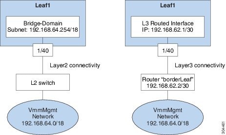
管理接続モード
APIC から vCenter、TACACS、または RADIUS サーバなどの外部エンティティへの接続を、インバンド管理ネットワークを使用して確立する必要があります。 vCenter Server などの外部エンティティへの接続を確立するために、次の 2 種類のモードが使用できます。
-
レイヤ 2 管理接続:外部エンティティがレイヤ 2 でリーフ ノードに接続されている場合、このモードを使用します。
-
レイヤ 3 管理接続:外部エンティティがルータを介しレイヤ 3 でリーフ ノードに接続されている場合、このモードを使用します。 リーフは外部エンティティに到達可能なルータに接続されます。
(注)
-
インバンド IP アドレス範囲はリーフ ノードからファブリックの外へのレイヤ 3 接続で使用される IP アドレス範囲と重複なしに分離しておく必要があります。
-
レイヤ 3 インバンド管理の設計はトポロジのスパイン ファブリック ノードへのインバンド管理アクセスを提供しません。
-
次の図に、接続を確立するために使用可能な 2 種類のモードを示します。
- GUI を使用したレイヤ 2 管理接続の設定
- REST API を使用したレイヤ 2 管理接続の設定
- CLI を使用したレイヤ 2 管理接続の設定
- GUI を使用したレイヤ 3 管理接続の設定
- REST API を使用したレイヤ 3 管理接続の設定
- CLI を使用したレイヤ 3 管理接続の設定
- 管理接続の検証
GUI を使用したレイヤ 2 管理接続の設定
(注) |
|
vCenter のドメイン プロファイルを作成する前に、インバンド管理ネットワークを使用して外部ネットワークを確立するための接続を確立する必要があります。
管理接続ポリシーの一部として設定された IP アドレス範囲が、ACI ファブリックで使用されるインフラストラクチャの IP アドレス範囲と重複しないことを確認してください。
| ステップ 1 | メニュー バーで、 を選択します。 |
| ステップ 2 | [Navigation] ペインで、 を展開し、[Bridge Domains] を右クリックして [Create Bridge Domain] をクリックします。 |
| ステップ 3 | [Create Bridge Domain] ダイアログボックスで、次の操作を実行します。 |
| ステップ 4 | [Navigation] ペインで、[Tenant mgmt] > [Application Profiles] を展開し、[Create Application Profile] をクリックして vCenter との接続を作成します。 |
| ステップ 5 |
[Create Application Profile] ダイアログボックスで、次の操作を実行します。
|
REST API を使用したレイヤ 2 管理接続の設定
(注) |
この作業での文字列の例として名前 vmm を使用します。 |
ポリシーは、Tenant-mgmt 配下に次のオブジェクトを作成します。
ブリッジ ドメイン(vmm)および次の関連オブジェクトを以下のように作成します。
-
そのブリッジ ドメインに IPプレフィックス(192.168.64.254/18)を持つサブネット オブジェクトを作成します。 この IP アドレス(192.168.64.254)は、従来のスイッチ設定でスイッチ仮想インターフェイス(SVI)として通常使用されるブリッジ ドメインに割り当てられます。
-
インバンド ネットワーク(ctx)へのアソシエーションを作成します。
次のように,アプリケーション プロファイル(vmm)と管理 EPG (vmmMgmt)および関連オブジェクトを作成します。
vCenter のドメイン プロファイルを作成する前に、インバンド管理ネットワークを使用して外部ネットワークを確立するための接続を確立する必要があります。
管理接続ポリシーの一部として設定された IP アドレス範囲が、ACI ファブリックで使用されるインフラストラクチャの IP アドレス範囲と重複しないことを確認してください。
|
例: <!-- api/policymgr/mo/.xml -->
<polUni>
<fvTenant name="mgmt">
<fvBD name="vmm">
<fvRsCtx tnFvCtxName="inb"/>
<fvSubnet ip='192.168.64.254/18'/>
</fvBD>
<fvAp name="vmm">
<fvAEPg name="vmmMgmt">
<fvRsBd tnFvBDName="vmm" />
<fvRsPathAtt tDn="topology/pod-1/paths-101/pathep-[eth1/40]" encap="vlan-11"/>
<fvRsCons tnVzBrCPName="default"/>
<fvRsDomAtt tDn="uni/phys-inband"/>
</fvAEPg>
</fvAp>
</fvTenant>
</polUni>
|
CLI を使用したレイヤ 2 管理接続の設定
(注) |
|
vCenter のドメイン プロファイルを作成する前に、インバンド管理ネットワークを使用して外部ネットワークを確立するための接続を確立する必要があります。
管理接続ポリシーの一部として設定された IP アドレス範囲が、ACI ファブリックで使用されるインフラストラクチャの IP アドレス範囲と重複しないことを確認してください。
| ステップ 1 |
CLI で、ディレクトリを /aci に変更します。 例: admin@apic1:~> cd /aci |
| ステップ 2 |
レイヤ 2 管理接続を確立するために、管理テナント用ブリッジ ドメインを作成し、ブリッジ ドメイン用のサブネットを作成し、管理テナントおよび管理アプリケーション EPG のアプリケーション プロファイルを作成し、ブリッジ ドメインが EPG に使用されるように接続し、スタティック ルートが EPG によって使用されるように設定します。 例: admin@apic1:~> cd /aci/tenants/mgmt/networking/bridge-domains admin@apic1:bridge-domains> mocreate vmm admin@apic1:bridge-domains> moconfig commit Committing mo 'tenants/mgmt/networking/bridge-domains/vmm' All mos committed successfully. admin@apic1:bridge-domains> cd vmm/ admin@apic1:vmm> moset network inb admin@apic1:vmm> cd subnets admin@apic1:subnets> mocreate 192.168.64.254/18 admin@apic1:subnets> moconfig commit Committing mo 'tenants/mgmt/networking/bridge-domains/vmm' Committing mo 'tenants/mgmt/networking/bridge-domains/vmm/subnets/192.168.64.254:18' All mos committed successfully. admin@apic1:subnets> admin@apic1:subnets> cd ../../../../application-profiles/ admin@apic1:application-profiles> mocreate vmm admin@apic1:application-profiles> moconfig commit Committing mo 'tenants/mgmt/application-profiles/vmm' All mos committed successfully. admin@apic1:application-profiles> admin@apic1:application-profiles> cd vmm/application-epgs admin@apic1:application-epgs> mocreate vmmMgmt admin@apic1:application-epgs> moconfig commit Committing mo 'tenants/mgmt/application-profiles/vmm/application-epgs/vmmMgmt' All mos committed successfully. admin@apic1:application-epgs> admin@apic1:application-epgs> cd vmmMgmt/static-bindings-paths admin@apic1:static-bindings-paths> mocreate topology/pod-1/paths-101/pathep-[eth1/40] encap vlan-11 admin@apic1:static-bindings-paths> moconfig commit Committing mo 'tenants/mgmt/application-profiles/vmm/application-epgs/vmmMgmt/static-bindings-paths/[topology/pod-1/paths-101/pathep-[eth1/40]]' All mos committed successfully. admin@apic1:static-bindings-paths> admin@apic1:static-bindings-paths> cd ../contracts/consumed-contracts admin@apic1:consumed-contracts> mocreate default admin@apic1:consumed-contracts> moconfig commit Committing mo 'tenants/mgmt/application-profiles/vmm/application-epgs/vmmMgmt/contracts/consumed-contracts/default' All mos committed successfully. admin@apic1:consumed-contracts> admin@apic1:consumed-contracts> admin@apic1:consumed-contracts> cd ../../domains-vms-and-bare-metals admin@apic1:domains-vms-and-bare-metals> mocreate fabric/access-policies/physical-and-external-domains/physical-domains/inband admin@apic1:domains-vms-and-bare-metals> moconfig commit Committing mo 'tenants/mgmt/application-profiles/vmm/application-epgs/vmmMgmt/domains-vms-and-bare-metals/[fabric /access-policies/physical-and-external-domains/physical-domains/inband]' All mos committed successfully. admin@apic1:domains-vms-and-bare-metals> |
GUI を使用したレイヤ 3 管理接続の設定
(注) |
この作業での文字列の例として名前 vmm を使用します。 このタスク例のビデオを視聴するには、Videos Webpage を参照してください。 |
VMM ドメイン プロファイルを作成する前に、インバンド管理ネットワークを使用して外部ネットワークに接続を確立します。
管理接続ポリシーの一部として設定された IP アドレス範囲が、ACI ファブリックで使用されるインフラストラクチャの IP アドレス範囲と重複しないことを確認してください。
| ステップ 1 | メニュー バーで、 を選択します。 |
| ステップ 2 | [Navigation] ペインで、次の操作を実行します。 |
| ステップ 3 |
[Create Routed Outside] ダイアログボックスで、次の操作を実行します。
|
| ステップ 4 |
[Nodes and Interfaces Protocol Profiles] を展開します。 [Create Node Profile] ダイアログボックスで、次の操作を実行します。
|
| ステップ 5 |
[Interface Profiles] を展開します。 [Create Interface Profile] ダイアログボックスで、次の操作を実行します。
|
| ステップ 6 | [Create Routed Outside] ダイアログボックスで、[Next] をクリックし、[External EPG Networks] を展開します。 |
| ステップ 7 |
[Create External Network] ダイアログボックスで、次の操作を実行します。
|
| ステップ 8 | [Navigation] ペインで、[External Routed Networks] と以前に作成した L3 ルーテッド外部ポリシー(vmm)を展開します。 [Networks] を選択し、以前に作成した外部ネットワーク(vmmMgmt)をクリックします。 |
| ステップ 9 |
[Work] ペインで、[Consumed Contracts] 領域を拡大します。 [Name] フィールドで、ドロップダウン リストから、デフォルトのコントラクトを選択します。 [Update] を選択します。 このコントラクトは、APIC およびスイッチが存在するインバンド EPG と VMM サーバが存在する EPG の間にあります。 |
| ステップ 10 | レイヤ 3 管理接続の構成を完了するには、[Submit] をクリックします。 |
REST API を使用したレイヤ 3 管理接続の設定
この作業での文字列の例として名前 vmm を使用します。
ポリシーは、Tenant-mgmt 配下に次のオブジェクトを作成します。
管理接続ポリシーの一部として設定された IP アドレス範囲が、ACI ファブリックで使用されるインフラストラクチャの IP アドレス範囲と重複しないことを確認してください。
|
例: <!-- api/policymgr/mo/.xml -->
<polUni>
<fvTenant name="mgmt">
<l3extOut name="vmm">
<l3extInstP name="vmmMgmt">
<l3extSubnet ip="192.168.0.0/16" />
<fvRsCons tnVzBrCPName="default" />
</l3extInstP>
<l3extLNodeP name="borderLeaf">
<l3extRsNodeL3OutAtt tDn="topology/pod-1/node-101" rtrId="1.2.3.4">
<ipRouteP ip="192.168.64.0/18">
<ipNexthopP nhAddr="192.168.62.2" />
</ipRouteP>
</l3extRsNodeL3OutAtt>
<l3extLIfP name="portProfile">
<l3extRsPathL3OutAtt tDn="topology/pod-1/paths-101/pathep-[eth1/40]" ifInstT="l3-port" addr="192.168.62.1/30" />
</l3extLIfP>
</l3extLNodeP>
<l3extRsEctx tnFvCtxName="inb" />
</l3extOut>
</fvTenant>
</polUni>
|
CLI を使用したレイヤ 3 管理接続の設定
この作業での文字列の例として名前 vmm を使用します。
VMM ドメイン プロファイルを作成する前に、インバンド管理ネットワークを使用して外部ネットワークに接続を確立する必要があります。
管理接続ポリシーの一部として設定された IP アドレス範囲が、ACI ファブリックで使用されるインフラストラクチャの IP アドレス範囲と重複しないことを確認してください。
| ステップ 1 |
CLI で、ディレクトリを /aci に変更します。 例: admin@apic1:~> cd /aci |
| ステップ 2 |
リーフ ポートに接続されたルータを使用して、 APIC から外部ルートに接続を確立します。 例: admin@apic1:~> cd /.aci/viewfs/tenants/mgmt/networking/external-routed-networks/
admin@apic1:external-routed-networks> mocreate l3-outside vmm
admin@apic1:external-routed-networks> moconfig commit
Committing mo 'tenants/mgmt/networking/external-routed-networks/l3-outside-vmm'
All mos committed successfully.
admin@apic1:external-routed-networks> cd l3-outside-vmm/networks/
admin@apic1:networks> mocreate vmmMgmt
admin@apic1:networks> moconfig commit
Committing mo 'tenants/mgmt/networking/external-routed-networks/l3-outside-vmm/networks/vmmMgmt'
All mos committed successfully.
admin@apic1:networks> cd vmmMgmt/consumed-contracts/
admin@apic1:consumed-contracts> mocreate default
admin@apic1:consumed-contracts> moconfig commit
Committing mo 'tenants/mgmt/networking/external-routed-networks/l3-outside-vmm/networks/vmmMgmt/consumed-contracts/default'
All mos committed successfully.
admin@apic1:consumed-contracts> cd ../subnets/
admin@apic1:subnets> mocreate 192.168.0.0/16
admin@apic1:subnets> moconfig commit
Committing mo 'tenants/mgmt/networking/external-routed-networks/l3-outside-vmm/networks/vmmMgmt/subnets/192.168.0.0:16'
All mos committed successfully.
admin@apic1:subnets> cd ../../../logical-node-profiles
admin@apic1:logical-node-profiles> mocreate borderLeaf
admin@apic1:logical-node-profiles> moconfig commit
Committing mo 'tenants/mgmt/networking/external-routed-networks/l3-outside-vmm/logical-node-profiles/borderLeaf'
All mos committed successfully.
admin@apic1:logical-node-profiles> cd borderLeaf/nodes/
admin@apic1:nodes> mocreate fabric/inventory/pod-1/node-101 router-id 1.2.3.4
admin@apic1:nodes> moconfig commit
Committing mo 'tenants/mgmt/networking/external-routed-networks/l3-outside-vmm/logical-node-profiles/borderLeaf/nodes
/[fabric/inventory/pod-1/node-101]'
All mos committed successfully.
admin@apic1:nodes> cd [fabric--inventory--pod-1--node-101]
admin@apic1:[fabric--inventory--pod-1--node-101]> mocreate 192.168.64.0/18
admin@apic1:[fabric--inventory--pod-1--node-101]> moconfig commit
Committing mo 'tenants/mgmt/networking/external-routed-networks/l3-outside-vmm/logical-node-profiles/borderLeaf/nodes
/[fabric/inventory/pod-1/node-101]/192.168.64.0:18'
All mos committed successfully.
admin@apic1:[fabric--inventory--pod-1--node-101]> cd 192.168.64.0:18/
admin@apic1:192.168.64.0:18> mocreate 192.168.62.2
admin@apic1:192.168.64.0:18> moconfig commit
Committing mo 'tenants/mgmt/networking/external-routed-networks/l3-outside-vmm/logical-node-profiles/borderLeaf/nodes
/[fabric/inventory/pod-1/node-101]/192.168.64.0:18/192.168.62.2'
All mos committed successfully.
admin@apic1:192.168.64.0:18> cd ../../../logical-interface-profiles/
admin@apic1:logical-interface-profiles> mocreate portProfile1
admin@apic1:logical-interface-profiles> moconfig commit
Committing mo 'tenants/mgmt/networking/external-routed-networks/l3-outside-vmm/logical-node-profiles/borderLeaf
/logical-interface-profiles/portProfile1'
All mos committed successfully.
admin@apic1:logical-interface-profiles> cd portProfile1/routed-interfaces/
admin@apic1:routed-interfaces> mocreate topology/pod-1/paths-101/pathep-[eth1/40] ip-address 192.168.62.1/30
admin@apic1:routed-interfaces> moconfig commit
Committing mo 'tenants/mgmt/networking/external-routed-networks/l3-outside-vmm/logical-node-profiles/borderLeaf
/logical-interface-profiles/portProfile1/routed-interfaces/[topology/pod-1/paths-101/pathep-[eth1/40]]'
All mos committed successfully.
admin@apic1:routed-interfaces> cd ../../../../../
admin@apic1:l3-outside-vmm> moset private-network inb
admin@apic1:l3-outside-vmm> moconfig commit
Committing mo 'tenants/mgmt/networking/external-routed-networks/l3-outside-vmm'
All mos committed successfully.
admin@apic1:l3-outside-vmm>
|
管理接続の検証
この検証プロセスは、レイヤ 2 とレイヤ 3 の両方のモードに適用でき、APIC GUI、REST API、または CLI を使用して確立された接続の確認に使用できます。
管理接続の確立手順を完了した後、コンソールにログインします。 到達可能な vCenter の IP アドレス(例、192.168.81.2)に対し、ping を実行して成功することを確認します。 この操作で、ポリシーが正常に適用されたことが示されます。
仮想マシンのネットワーキング ポリシーの設定
APIC は、サードパーティ VM 管理システム(VMware vCenterなど)と統合化することによって、ACI のメリットを仮想化インフラストラクチャに拡張します。 APIC は、VM 管理システム内の ACI ポリシーを管理者が使用できるようにします。
VM 管理システムについて
(注) |
このマニュアルは、vCenter との統合に必要な APIC の設定について説明します。 VMware コンポーネントの設定手順については、VMware のマニュアルを参照してください。 |
以下は、VM 管理システムの用語の説明です。
-
VM コントローラは、VMware vCenter、VMware vShield、Microsoft Systems Center Virtual Machine Manager(SCVMM)などの外部仮想マシンの管理エンティティです。 APIC は、コントローラと通信し、仮想ワークロードに適用されるネットワーク ポリシーを公開します。 VM コントローラの管理者は、APIC 管理者に VM コントローラの認証クレデンシャルを提供します。同じタイプの複数のコントローラが同じクレデンシャルを使用できます。
-
クレデンシャルは、VM コントローラと通信するための認証クレデンシャルを表します。 複数のコントローラが同じクレデンシャルを使用できます。
-
仮想マシンのモビリティ ドメイン(vCenter のモビリティ ドメイン)は、同様のネットワーキング ポリシー要件を持つ VM コントローラのグループです。 この必須コンテナは、VLAN プールなどのためのポリシー、サーバ/ネットワーク MTU ポリシー、またはサーバ/ネットワーク アクセス LACP ポリシーを持つ 1 つ以上の VM コントローラを保持します。 エンドポイント グループが vCenter ドメインに関連付けられると、ネットワーク ポリシーが vCenter ドメイン内のすべての VM コントローラにプッシュされます。
-
プールは、トラフィックのカプセル化 ID の範囲を表します(たとえば、VLAN ID、VNID、マルチキャスト アドレスなど)。 プールは共有リソースで、VMM などの複数のドメインおよびレイヤ 4 ~ レイヤ 7 のサービスで消費できます。 リーフ スイッチは、重複した VLAN プールをサポートしていません。 異なる重複した VLAN プールを同一の接続可能エンティティ プロファイル(AEP)と関連付けることはできません。 VLAN ベースのプールには、次の 2 種類があります。
接続可能エンティティ プロファイルについて
接続エンティティ プロファイル
ACI ファブリックにより、リーフ ポートを通して baremetal サーバ、ハイパーバイザ、レイヤ 2 スイッチ(たとえば、Cisco UCS ファブリック インターコネクト)、レイヤ 3 ルータ(たとえば、Cisco Nexus 7000 シリーズ スイッチ)などのさまざまな外部エンティティに接続する複数の接続ポイントが提供されます。 これらの接続ポイントは、リーフ スイッチ上の物理ポート、ポート チャネル、または仮想ポート チャネル(vPC)にすることができます。
接続可能エンティティ プロファイル(AEP)は、同様のインフラストラクチャ ポリシー要件を持つ外部エンティティのグループを表します。 インフラストラクチャ ポリシーは、物理インターフェイス ポリシーで構成され、たとえば Cisco Discovery Protocol(CDP)、Link Layer Discovery Protocol(LLDP)、最大伝送単位(MTU)、Link Aggregation Control Protocol(LACP)などがあります。
VM 管理(VMM)ドメインは、AEP に関連付けられたインターフェイス ポリシー グループから物理インターフェイス ポリシーを自動的に取得します。
-
AEP でオーバーライド ポリシーを VMM ドメイン用の別の物理インターフェイス ポリシーを指定するために使用できます。 このポリシーは、ハイパーバイザが中間レイヤ 2 ノードを介してリーフ スイッチに接続され、異なるポリシーがリーフ スイッチおよびハイパーバイザの物理ポートで要求される場合に役立ちます。 たとえば、リーフ スイッチとレイヤ 2 ノード間で LACP を設定できます。 同時に、AEP オーバーライド ポリシーで LACP をディセーブルにすることで、ハイパーバイザとレイヤ 2 スイッチ間の LACP をディセーブルにできます。
AEP は、リーフ スイッチで VLAN プールを展開するのに必要です。 異なるリーフ スイッチ間でカプセル化プール(たとえば VLAN)を再利用することができます。 AEP は、(VMM ドメインに関連付けられた)VLAN プールの範囲を物理インフラストラクチャに暗黙的に提供します。
(注) |
|
VMM ドメイン プロファイルの作成
作業例を次に示します。
VMM ドメイン プロファイルを作成するための前提条件
GUI を使用した vCenter ドメイン プロファイルの作成
(注) |
このタスク例のビデオを視聴するには、Videos Webpage を参照してください。 |
VMM ドメイン プロファイルを作成する前に、APIC のインバンド管理ネットワークを使用して外部ネットワークへの接続を確立する必要があります。
| ステップ 1 | メニュー バーで、 を選択します。 | ||
| ステップ 2 | [Navigation] ペインで、[VM Provider VMware] を右クリックし、[Create vCenter Domain] をクリックします。 | ||
| ステップ 3 | [Create vCenter Domain] ダイアログボックスで、[Name](productionDC)を入力します。 | ||
| ステップ 4 |
[Virtual Switch] フィールドで、該当するオプション ボタンをクリックします。
|
||
| ステップ 5 |
]Associated Attachable EntityProfile] フィールドで、ドロップダウン リストから、[Create Attachable Entity Profile] を選択し、VMM ドメインの範囲全体にわたるスイッチ インターフェイスのリストを設定するために、次の手順を実行します。
|
||
| ステップ 6 |
|
||
| ステップ 7 |
[vCenter Credentials] クレデンシャルを展開します。 [Create vCenter Credential] ダイアログボックスで、ユーザ アカウントを作成するために、次の操作を実行します。
|
||
| ステップ 8 |
次の手順に従って、新しいドメインとプロファイルを確認してください。
[Navigation] ペインで、VMM ドメイン名を参照して、コントローラがオンラインであることを確認します。 [Work] ペインに、vcenter1 のプロパティが動作状態を含めて表示されます。 この表示情報で、APIC から vCenter サーバへの接続が確立されたことと、インベントリが使用可能であることを確認します。 |
REST API を使用した vCenter ドメイン プロファイルの作成
| ステップ 1 |
VMM ドメイン名、コントローラ、およびユーザ クレデンシャルを設定します。 例: https://<api-ip>/api/node/mo/.xml <polUni> <vmmProvP vendor="VMware"> <!-- VMM Domain --> <vmmDomP name="productionDC"> <!-- Association to VLAN Namespace --> <infraRsVlanNs tDn="uni/infra/vlanns-VlanRange-dynamic"/> <!-- Credentials for vCenter --> <vmmUsrAccP name="admin" usr="administrator" pwd="admin" /> <!-- vCenter IP address --> <vmmCtrlrP name="vcenter1" hostOrIp="<vcenter ip address>" rootContName="<Datacenter Name in vCenter>"> <vmmRsAcc tDn="uni/vmmp-VMware/dom-productionDC/usracc-admin"/> </vmmCtrlrP> </vmmDomP> </vmmProvP> |
| ステップ 2 |
VLAN の名前空間配置のための接続可能エンティティ プロファイルを作成します。 例: https://<apic-ip>/api/policymgr/mo/uni.xml <infraInfra> <infraAttEntityP name="profile1"> <infraRsDomP tDn="uni/vmmp-VMware/dom-productionDC"/> </infraAttEntityP> </infraInfra> |
| ステップ 3 |
インターフェイス ポリシー グループおよびセレクタを作成します。 例: https://<apic-ip>/api/policymgr/mo/uni.xml
<infraInfra>
<infraAccPortP name="swprofile1ifselector">
<infraHPortS name="selector1" type="range">
<infraPortBlk name="blk"
fromCard="1" toCard="1" fromPort="1" toPort="3">
</infraPortBlk>
<infraRsAccBaseGrp tDn="uni/infra/funcprof/accportgrp-group1" />
</infraHPortS>
</infraAccPortP>
<infraFuncP>
<infraAccPortGrp name="group1">
<infraRsAttEntP tDn="uni/infra/attentp-profile1" />
</infraAccPortGrp>
</infraFuncP>
</infraInfra>
|
| ステップ 4 |
スイッチ プロファイルを作成します。 例: https://<apic-ip>/api/policymgr/mo/uni.xml
<infraInfra>
<infraNodeP name="swprofile1">
<infraLeafS name="selectorswprofile11718" type="range">
<infraNodeBlk name="single0" from_="101" to_="101"/>
<infraNodeBlk name="single1" from_="102" to_="102"/>
</infraLeafS>
<infraRsAccPortP tDn="uni/infra/accportprof-swprofile1ifselector"/>
</infraNodeP>
</infraInfra>
|
| ステップ 5 |
VLAN プールを設定します。 例: https://<apic-ip>/api/node/mo/.xml <polUni> <infraInfra> <fvnsVlanInstP name="VlanRange" allocMode="dynamic"> <fvnsEncapBlk name="encap" from="vlan-100" to="vlan-400"/> </fvnsVlanInstP> </infraInfra> </polUni> |
| ステップ 6 |
設定されたすべてのコントローラとそれらの動作状態を確認します。 例: GET: https://<apic-ip>/api/node/class/compCtrlr.xml? <imdata> <compCtrlr apiVer="5.1" ctrlrPKey="uni/vmmp-VMware/dom-productionDC/ctrlr-vcenter1" deployIssues="" descr="" dn="comp/prov-VMware/ctrlr-productionDC-vcenter1" domName=" productionDC" hostOrIp="esx1" mode="default" model="VMware vCenter Server 5.1.0 build-756313" name="vcenter1" operSt="online" port="0" pwd="" remoteOperIssues="" scope="vm" usr="administrator" vendor="VMware, Inc." ... /> </imdata> |
| ステップ 7 |
VMM ドメイン「ProductionDC」下の「vcenter1」という名前の vCenter 用ハイパーバイザと VM を確認します。 例: GET: https://<apic-ip>/api/node/mo/comp/prov-VMware/ctrlr-productionDC-vcenter1.xml?query-target=children <imdata> <compHv descr="" dn="comp/prov-VMware/ctrlr-productionDC-vcenter1/hv-host-4832" name="esx1" state="poweredOn" type="hv" ... /> <compVm descr="" dn="comp/prov-VMware/ctrlr-productionDC-vcenter1/vm-vm-5531" name="AppVM1" state="poweredOff" type="virt" .../> <hvsLNode dn="comp/prov-VMware/ctrlr-productionDC-vcenter1/sw-dvs-5646" lacpEnable="yes" lacpMode="passive" ldpConfigOperation="both" ldpConfigProtocol="lldp" maxMtu="1500" mode="default" name="apicVswitch" .../> </imdata> |
CLI を使用した vCenter ドメイン プロファイルの作成
| ステップ 1 |
CLI で、ディレクトリを /aci に変更します。 例: admin@apic1:~> cd /aci |
| ステップ 2 |
VMM ドメイン名、コントローラ、およびユーザ クレデンシャルを設定します。 例: admin@apic1:~> cd /aci/vm-networking/policies/vmware/vmm-domains/ admin@apic1:vmm-domains> mocreate productionDC admin@apic1:vmm-domains> moconfig commit Committing mo 'vm-networking/policies/vmware/vmm-domains/productionDC' All mos committed successfully. admin@apic1:vmm-domains> cd productionDC/ admin@apic1:productionDC> moset vlan-pool fabric/access-policies/pools/vlan/vlanRange-dynamic-allocation admin@apic1:productionDC> moconfig commit Committing mo 'vm-networking/policies/vmware/vmm-domains/productionDC' All mos committed successfully. admin@apic1:productionDC> admin@apic1:productionDC> cd /aci/vm-networking/policies/vmware/vmm-domains/productionDC/controllers/ admin@apic1:controllers> mocreate vcenter1 admin@apic1:controllers> cd vcenter1 admin@apic1:vcenter1> moset host-name-or-ip-address 192.168.81.2 admin@apic1:vcenter1> moset datacenter Datacenter1 admin@apic1:vcenter1> moset management-epg tenants/mgmt/networking/external-routed-networks/l3-outside-extMgmt/networks/extNetwork admin@apic1:vcenter1> moset associated-credential uni/vmmp-VMware/dom-productionDC/usracc-admin admin@apic1:vcenter1> moconfig commit Committing mo 'vm-networking/policies/vmware/vmm-domains/productionDC/controllers/vcenter1' All mos committed successfully. admin@apic1:vcenter1> admin@apic1:vcenter1> cd /aci/vm-networking/policies/vmware/vmm-domains/productionDC/credentials admin@apic1:credentials> mocreate admin admin@apic1:credentials> moconfig commit Committing mo 'vm-networking/policies/vmware/vmm-domains/productionDC/credentials/admin' All mos committed successfully. admin@apic1:credentials> cd admin/ admin@apic1:admin> moset username administrator admin@apic1:admin> moset password Password: <admin> Verify: <admin> admin@apic1:admin> moconfig commit Committing mo 'vm-networking/policies/vmware/vmm-domains/productionDC/credentials/admin' All mos committed successfully. |
| ステップ 3 |
VLAN の名前空間配置のための接続可能エンティティ プロファイルを作成します。 例: admin@apic1:~> cd /aci/fabric/access-policies/global-policies/attachable-entity-profile/ admin@apic1:attachable-entity-profile> mocreate profile1 admin@apic1:attachable-entity-profile> moconfig commit Committing mo 'fabric/access-policies/global-policies/attachable-entity-profile/profile1' All mos committed successfully. admin@apic1:attachable-entity-profile> cd profile1/ admin@apic1:profile1> cd domains-associated-to-interfaces/ admin@apic1:domains-associated-to-interfaces> mocreate uni/vmmp-VMware/dom-productionDC admin@apic1:domains-associated-to-interfaces> moconfig commit Committing mo 'fabric/access-policies/global-policies/attachable-entity-profile/profile1/domains-associated-to-interfaces/[vm-networking /policies/vmware/vmm-domains/productionDC]' All mos committed successfully. admin@apic1:domains-associated-to-interfaces> |
| ステップ 4 |
インターフェイス ポリシー グループおよびセレクタを作成します。 例: admin@apic1:~> cd /aci/fabric/access-policies/interface-policies/policy-groups/interface admin@apic1:interface> mocreate group1 admin@apic1:interface> moconfig commit Committing mo 'fabric/access-policies/interface-policies/policy-groups/interface/group1' All mos committed successfully. admin@apic1:interface> cd group1 admin@apic1:group1> moset attached-entity-profile fabric/access-policies/global-policies/attachable-entity-profile/profile1 admin@apic1:group1> moconfig commit Committing mo 'fabric/access-policies/interface-policies/policy-groups/interface/group1' All mos committed successfully. admin@apic1:group1> admin@apic1:group1> cd ../../../ admin@apic1:interface-policies> cd profiles/interfaces/ admin@apic1:interfaces> mocreate swprofile1ifselector admin@apic1:interfaces> cd swprofile1ifselector admin@apic1:swprofile1ifselector> moset description 'GUI Interface Selector Generated PortP Profile swprofile1' admin@apic1:swprofile1ifselector> moconfig commit Committing mo 'fabric/access-policies/interface-policies/profiles/interfaces/swprofile1ifselector' All mos committed successfully. admin@apic1:swprofile1ifselector> mocreate selector1 range admin@apic1:swprofile1ifselector> cd selector1-range admin@apic1:selector1-range> moset policy-group fabric/access-policies/interface-policies/policy-groups/interface/group1 admin@apic1:selector1-range> mocreate block1 admin@apic1:selector1-range> cd block1 admin@apic1:block1> moset from-port 1 admin@apic1:block1> moset to-port 3 admin@apic1:block1> moconfig commit Committing mo 'fabric/access-policies/interface-policies/profiles/interfaces/swprofile1ifselector/selector1-range' Committing mo 'fabric/access-policies/interface-policies/profiles/interfaces/swprofile1ifselector/selector1-range/block1' All mos committed successfully. admin@apic1:block1> |
| ステップ 5 |
スイッチ プロファイルを作成します。 例: admin@apic1:~> cd /aci/fabric/access-policies/switch-policies/profiles/ admin@apic1:profiles> mocreate swprofile1 admin@apic1:profiles> cd swprofile1/ admin@apic1:swprofile1> moset description 'GUI Interface Selector Generated Profile: swprofile1' admin@apic1:swprofile1> cd switch-selectors/ admin@apic1:switch-selectors> mocreate selectorswprofile11718 range admin@apic1:switch-selectors> cd selectorswprofile11718-range/ admin@apic1:selectorswprofile11718-range> mocreate single0 admin@apic1:selectorswprofile11718-range> cd single0/ admin@apic1:single0> moset from 101 admin@apic1:single0> moset to 101 admin@apic1:single0> cd ../ admin@apic1:selectorswprofile11718-range> mocreate single1 admin@apic1:selectorswprofile11718-range> cd single1/ admin@apic1:single1> moset from 102 admin@apic1:single1> moset to 102 admin@apic1:single1> moconfig commit Committing mo 'fabric/access-policies/switch-policies/profiles/swprofile1' Committing mo 'fabric/access-policies/switch-policies/profiles/swprofile1/switch-selectors/selectorswprofile11718-range' Committing mo 'fabric/access-policies/switch-policies/profiles/swprofile1/switch-selectors/selectorswprofile11718-range/single1' Committing mo 'fabric/access-policies/switch-policies/profiles/swprofile1/switch-selectors/selectorswprofile11718-range/single0' All mos committed successfully. admin@apic1:single1> cd ../../../ admin@apic1:swprofile1> cd associated-interface-selector-profiles/ admin@apic1:associated-interface-selector-profiles> mocreate fabric/access-policies/interface-policies/profiles/interfaces/swprofile1ifselector admin@apic1:associated-interface-selector-profiles> moconfig commit Committing mo 'fabric/access-policies/switch-policies/profiles/swprofile1/associated-interface-selector-profiles /[fabric/access-policies/interface-policies/profiles/interfaces/swprofile1ifselector]' All mos committed successfully. admin@apic1:associated-interface-selector-profiles> |
| ステップ 6 |
VLAN プールを設定します。 例: admin@apic1:~> cd /aci/fabric/access-policies/pools/vlan/ admin@apic1:vlan> mocreate VlanRange dynamic-allocation admin@apic1:vlan> moconfig commit Committing mo 'fabric/access-policies/pools/vlan/VlanRange-dynamic-allocation' All mos committed successfully. admin@apic1:vlan> cd VlanRange-dynamic-allocation/encap-blocks/ admin@apic1:encap-blocks> mocreate vlan100 vlan400 admin@apic1:encap-blocks> moconfig commit Committing mo 'fabric/access-policies/pools/vlan/VlanRange-dynamic-allocation/encap-blocks/vlan100-vlan400' All mos committed successfully. admin@apic1:encap-blocks> |
GUI を使用した vCenter および vShield ドメイン プロファイルの作成
(注) |
このタスク例のビデオを視聴するには、Videos Webpage を参照してください。 |
| ステップ 1 | メニュー バーで、 を選択します。 | ||
| ステップ 2 | [Navigation] ペインで、[VM Provider VMware] を右クリックし、[Create vCenter Domain] をクリックします。 | ||
| ステップ 3 | [Create vCenter Domain] ダイアログボックスで、[Name](productionDC)を入力します。 | ||
| ステップ 4 |
[Virtual Switch] フィールドで、該当するオプション ボタンをクリックします。
|
||
| ステップ 5 |
[Associated Attachable Entity Profile] ドロップダウン リストで、[Create Attachable Access Entity Profile] を選択し、次の操作を実行します。
|
||
| ステップ 6 |
|
||
| ステップ 7 |
[vCenter Credential] を展開して、ユーザ アカウントを作成するために [Create vCenter Credential] ダイアログボックスで、次の操作を実行します。
|
||
| ステップ 8 |
[vCenter Credentials] をもう一度展開します。 [Create vCenter Credential] ダイアログボックスで、ユーザ アカウントを作成するために、次の操作を実行します。
|
||
| ステップ 9 |
[vCenter/vShield] を展開し、次の作業を実行します。
|
||
| ステップ 10 |
次の手順に従って、新しいドメインとプロファイルを確認します。
|
REST API を使用した vCenter および vShield のドメイン プロファイルの作成
| ステップ 1 |
VLAN プールを作成します。 例: https://<apic-ip>/api/policymgr/mo/uni.xml
<polUni>
<infraInfra>
<fvnsVlanInstP name="vlan1" allocMode="dynamic">
<fvnsEncapBlk name="encap" from="vlan-100" to="vlan-400"/>
</fvnsVlanInstP>
</infraInfra>
</polUni>
|
| ステップ 2 |
vCenter のドメインを作成し、VLAN プールを割り当てます。 例: https://<apic-ip>/api/policymgr/mo/uni.xml <vmmProvP dn="uni/vmmp-VMware"> <vmmDomP name="productionDC"> <infraRsVlanNs tDn="uni/infra/vlanns-[vlan1]-dynamic"/> </vmmDomP> </vmmProvP> |
| ステップ 3 |
インフラストラクチャ VLAN 導入用の接続可能エンティティ プロファイルを作成します。 例: https://<apic-ip>/api/policymgr/mo/uni.xml
<infraInfra>
<infraAttEntityP name="profile1">
<infraRsDomP tDn="uni/vmmp-VMware/dom-productionDC"/>
<infraProvAcc name="provfunc"/>
</infraAttEntityP>
</infraInfra>
|
| ステップ 4 |
インターフェイス ポリシー グループおよびセレクタを作成します。 例: https://<apic-ip>/api/policymgr/mo/uni.xml
<infraInfra>
<infraAccPortP name="swprofile1ifselector">
<infraHPortS name="selector1" type="range">
<infraPortBlk name="blk"
fromCard="1" toCard="1" fromPort="1" toPort="3">
</infraPortBlk>
<infraRsAccBaseGrp tDn="uni/infra/funcprof/accportgrp-group1" />
</infraHPortS>
</infraAccPortP>
<infraFuncP>
<infraAccPortGrp name="group1">
<infraRsAttEntP tDn="uni/infra/attentp-profile1" />
</infraAccPortGrp>
</infraFuncP>
</infraInfra>
|
| ステップ 5 |
スイッチ プロファイルを作成します。 例: https://<apic-ip>/api/policymgr/mo/uni.xml
<infraInfra>
<infraNodeP name="swprofile1">
<infraLeafS name="selectorswprofile11718" type="range">
<infraNodeBlk name="single0" from_="101" to_="101"/>
<infraNodeBlk name="single1" from_="102" to_="102"/>
</infraLeafS>
<infraRsAccPortP tDn="uni/infra/accportprof-swprofile1ifselector"/>
</infraNodeP>
</infraInfra>
|
| ステップ 6 |
コントローラのクレデンシャルを作成します。 例: https://<apic-ip>/api/policymgr/mo/uni.xml
<vmmProvP dn="uni/vmmp-VMware">
<vmmDomP name="productionDC">
<vmmUsrAccP name="vcenter_user" usr="administrator" pwd="default"/>
<vmmUsrAccP name="vshield_user" usr="admin" pwd="default"/>
</vmmDomP>
</vmmProvP> |
| ステップ 7 |
vCenter コントローラを作成します。 例: <vmmProvP dn="uni/vmmp-VMware">
<vmmDomP name="productionDC">
<vmmCtrlrP name="vcenter1" hostOrIp="172.23.50.85">
<vmmRsAcc tDn="uni/vmmp-VMware/dom-productionDC/usracc-vcenter_user"/>
</vmmCtrlrP>
</vmmDomP>
</vmmProvP> |
| ステップ 8 |
VXLAN プールおよびマルチキャスト アドレス範囲を作成します。 例: https://<apic-ip>/api/policymgr/mo/uni.xml
<infraInfra>
<fvnsVxlanInstP name="vxlan1">
<fvnsEncapBlk name="encap" from="vxlan-6000" to="vxlan-6200"/>
</fvnsVxlanInstP>
<fvnsMcastAddrInstP name="multicast1">
<fvnsMcastAddrBlk name="mcast" from="224.0.0.1" to="224.0.0.20"/>
</fvnsMcastAddrInstP>
</infraInfra> |
| ステップ 9 |
vShield コントローラを作成します。 例: https://<apic-ip>/api/policymgr/mo/uni.xml
<vmmProvP dn="uni/vmmp-VMware">
<vmmDomP name="productionDC">
<vmmCtrlrP name="vshield1" hostOrIp="172.23.54.62" scope="iaas">
<vmmRsAcc tDn="uni/vmmp-VMware/dom-productionDC/usracc-vshield_user"/>
<vmmRsVmmCtrlrP tDn="uni/vmmp-VMware/dom-productionDC/ctrlr-vcenter1"/>
<vmmRsVxlanNs tDn="uni/infra/vxlanns-vxlan1"/>
<vmmRsMcastAddrNs tDn="uni/infra/maddrns-multicast1"/>
</vmmCtrlrP>
</vmmDomP>
</vmmProvP> |
CLI を使用した vCenter および vShield ドメイン プロファイルの作成
| ステップ 1 |
CLI で、ディレクトリを /aci に変更します。 例: admin@apic1:~> cd /aci |
| ステップ 2 |
VLAN プールを作成します。 例: admin@apic1:~> cd fabric/access-policies/pools/vlan admin@apic1:vlan> mocreate vlan1 dynamic-allocation admin@apic1:vlan> moconfig commit Committing mo 'fabric/access-policies/pools/vlan/vlan1-dynamic-allocation' All mos committed successfully. admin@apic1:vlan> cd vlan1-dynamic-allocation admin@apic1:vlan1-dynamic-allocation> cd encap-blocks admin@apic1:encap-blocks> mocreate vlan-100 vlan-400 admin@apic1:encap-blocks> moconfig commit Committing mo 'fabric/access-policies/pools/vlan/vlan1-dynamic-allocation/encap-blocks/vlan100-vlan400' All mos committed successfully. admin@apic1:encap-blocks> |
| ステップ 3 |
vCenter のドメインを作成し、ドメインに VLAN プールを割り当てます。 例: admin@apic1:~> cd /aci admin@apic1:~> cd vm-networking/policies/vmware/vmm-domains admin@apic1:vmm-domains> mocreate productionDC admin@apic1:vmm-domains> cd productionDC admin@apic1:productionDC> moset vlan-pool fabric/access-policies/pools/vlan/vlan1-dynamic-allocation admin@apic1:productionDC> moconfig commit Committing mo 'vm-networking/policies/vmware/vmm-domains/productionDC' All mos committed successfully. admin@apic1:productionDC> |
| ステップ 4 |
インフラストラクチャ VLAN 導入用の接続可能エンティティ プロファイルを作成します。 例: admin@apic1:~> cd /aci admin@apic1:~> cd fabric/access-policies/global-policies/attachable-entity-profile admin@apic1:attachable-entity-profile> mocreate profile1 admin@apic1:attachable-entity-profile> cd profile1 admin@apic1:profile1> cd domains-associated-to-interfaces admin@apic1:domains-associated-to-interfaces> mocreate uni/vmmp-VMware/dom-productionDC admin@apic1:domains-associated-to-interfaces> moconfig commit Committing mo 'fabric/access-policies/global-policies/attachable-entity-profile/profile1' Committing mo 'fabric/access-policies/global-policies/attachable-entity-profile/profile1/ domains-associated-to-interfaces/[uni/vmmp-VMware/dom-productionDC]' All mos committed successfully. admin@apic1:domains-associated-to-interfaces> cd .. admin@apic1:profile1> cd vlan-encapsulation-for-vxlan-traffic admin@apic1:vlan-encapsulation-for-vxlan-traffic> mocreate provfunc admin@apic1:vlan-encapsulation-for-vxlan-traffic> moconfig commit Committing mo 'fabric/access-policies/global-policies/attachable-entity-profile/profile1/ vlan-encapsulation-for-vxlan-traffic/provfunc' All mos committed successfully. admin@apic1:vlan-encapsulation-for-vxlan-traffic> |
| ステップ 5 |
インターフェイス ポリシー グループおよびセレクタを作成します。 例: admin@apic1:~> cd /aci admin@apic1:~> cd fabric/access-policies/interface-policies admin@apic1:interface-policies> cd policy-groups/interface admin@apic1:interface> mocreate group1 admin@apic1:interface> cd group1 admin@apic1:group1> moset attached-entity-profile fabric/access-policies/global-policies/ attachable-entity-profile/profile1 admin@apic1:group1> cd ../../.. admin@apic1:interface-policies> cd profiles/interfaces admin@apic1:interfaces> mocreate swprofile1ifselector admin@apic1:interfaces> cd swprofile1ifselector admin@apic1:swprofile1ifselector> moset description 'GUI Interface Selector Generated PortP Profile: swprofile1' admin@apic1:swprofile1ifselector> mocreate selector1 range admin@apic1:swprofile1ifselector> cd selector1-range admin@apic1:selector1-range> moset policy-group fabric/access-policies/interface-policies/policy-groups/ interface/group1 admin@apic1:selector1-range> mocreate block1 admin@apic1:selector1-range> cd block1 admin@apic1:block1> moset to-port 3 admin@apic1:block1> moconfig commit Committing mo 'fabric/access-policies/interface-policies/policy-groups/interface/group1' Committing mo 'fabric/access-policies/interface-policies/profiles/interfaces/swprofile1ifselector' Committing mo 'fabric/access-policies/interface-policies/profiles/interfaces/swprofile1ifselector/selector1-range' Committing mo 'fabric/access-policies/interface-policies/profiles/interfaces/swprofile1ifselector/selector1-range/block1' All mos committed successfully. admin@apic1:block1> |
| ステップ 6 |
スイッチ プロファイルを作成します。 例: admin@apic1:~> cd /aci admin@apic1:~> cd fabric/access-policies/switch-policies/profiles admin@apic1:profiles> mocreate swprofile1 admin@apic1:profiles> cd swprofile1 admin@apic1:swprofile1> cd switch-selectors admin@apic1::switch-selectors> moset description 'GUI Interface Selector Generated Profile: swprofile1' admin@apic1:swprofile1> mocreate leaf-selector selectorswprofile11718 range admin@apic1:swprofile1> cd leaf-selector-selectorswprofile11718-range admin@apic1:leaf-selector-selectorswprofile11718-range> mocreate single0 admin@apic1:leaf-selector-selectorswprofile11718-range> cd single0 admin@apic1:single0> moset from 17 admin@apic1:single0> moset to 17 admin@apic1:single0> cd .. admin@apic1:leaf-selector-selectorswprofile11718-range> mocreate single1 admin@apic1:leaf-selector-selectorswprofile11718-range> cd single1 admin@apic1:single1> moset from 18 admin@apic1:single1> moset to 18 admin@apic1:single1> moconfig commit Committing mo 'fabric/access-policies/switch-policies/profiles/swprofile1' Committing mo 'fabric/access-policies/switch-policies/profiles/swprofile1/leaf-selector-selectorswprofile11718-range' Committing mo 'fabric/access-policies/switch-policies/profiles/swprofile1/leaf-selector-selectorswprofile11718-range/single1' Committing mo 'fabric/access-policies/switch-policies/profiles/swprofile1/leaf-selector-selectorswprofile11718-range/single0' All mos committed successfully. admin@apic1:single1> cd ../../.. admin@apic1:swprofile1> cd associated-interface-selector-profiles admin@apic1:associated-interface-selector-profiles> mocreate fabric/access-policies/interface-policies/ profiles/interfaces/swprofile1ifselector admin@apic1:associated-interface-selector-profiles> moconfig commit Committing mo 'fabric/access-policies/switch-policies/profiles/swprofile1/associated-interface-selector-profiles/ [fabric/access-policies/interface-policies/profiles/interfaces/swprofile1ifselector]' All mos committed successfully. admin@apic1:associated-interface-selector-profiles> |
| ステップ 7 |
vCenter コントローラおよび vShield コントローラのクレデンシャルを作成します。 例: admin@apic1:~> cd /aci admin@apic1:~> cd vm-networking/policies/vmware/vmm-domains/productionDC admin@apic1:productionDC> cd credentials admin@apic1:controller-credentials> mocreate vcenter_user admin@apic1:controller-credentials> cd vcenter_user admin@apic1:vcenter_user> moset username administrator admin@apic1:vcenter_user> moset password default admin@apic1:vcenter_user> cd .. admin@apic1:controller-credentials> mocreate vshield_user admin@apic1:controller-credentials> cd vshield_user admin@apic1:vshield_user> moset username admin admin@apic1:vshield_user> moset password default admin@apic1:vshield_user> moconfig commit Committing mo 'vm-networking/policies/vmware/vmm-domains/productionDC/credentials/vcenter_user' Committing mo 'vm-networking/policies/vmware/vmm-domains/productionDC/credentials/vshield_user' All mos committed successfully. admin@apic1:vshield_user> |
| ステップ 8 |
vCenter コントローラを作成します。 例: admin@apic1:~> cd /aci admin@apic1:~> cd vm-networking/policies/vmware/vmm-domains/productionDC admin@apic1:productionDC> cd controllers admin@apic1:controllers> mocreate vcenter1 admin@apic1:controllers> cd vcenter1 admin@apic1:vcenter1> moset host-name-or-ip-address 172.23.50.85 admin@apic1:vcenter1> moset datacenter productionDC admin@apic1:vcenter1> moset management-epg uni/tn-mgmt/out-extMgmt/instP-extNetwork admin@apic1:vcenter1> moset associated-credential vm-networking/policies/vmware/vmm-domains/ productionDC/credentials/vcenter_user admin@apic1:vcenter1> moconfig commit Committing mo 'vm-networking/policies/vmware/vmm-domains/productionDC/controllers/vcenter1' All mos committed successfully. admin@apic1:vcenter1> |
| ステップ 9 |
VXLAN プールおよびマルチキャスト アドレスの範囲を作成します。 例: admin@apic1:~> cd /aci admin@apic1:~> cd fabric/access-policies/pools admin@apic1:pools> cd vxlan admin@apic1:vxlan> mocreate vxlan1 admin@apic1:vxlan> cd vxlan1 admin@apic1:vxlan1> cd encap-blocks admin@apic1:encap-blocks> mocreate vxlan-6000 vxlan-6200 admin@apic1:encap-blocks> moconfig commit Committing mo 'fabric/access-policies/pools/vxlan/vxlan1' Committing mo 'fabric/access-policies/pools/vxlan/vxlan1/encap-blocks/vxlan6000-vxlan6200' All mos committed successfully. admin@apic1:encap-blocks> cd ../../.. admin@apic1:pools> cd multicast-address admin@apic1:multicast-address> mocreate multicast1 admin@apic1:multicast-address> cd multicast1 admin@apic1:multicast1> cd address-blocks admin@apic1:address-blocks> mocreate 224.0.0.1 224.0.0.20 admin@apic1:address-blocks> moconfig commit Committing mo 'fabric/access-policies/pools/multicast-address/multicast1' Committing mo 'fabric/access-policies/pools/multicast-address/multicast1/address-blocks/224.0.0.1-224.0.0.20' All mos committed successfully. admin@apic1:address-blocks> |
| ステップ 10 |
vShield コントローラを作成します。 例: admin@apic1:~> cd /aci admin@apic1:~> cd vm-networking/policies/vmware/vmm-domains/productionDC admin@apic1:productionDC> cd controllers admin@apic1:controllers> mocreate vshield1 admin@apic1:controllers> cd vshield1 admin@apic1:vshield1> moset type vshield admin@apic1:vshield1> moset host-name-or-ip-address 172.23.54.62 admin@apic1:vshield1> moset datacenter productionDC admin@apic1:vshield1> moset management-epg uni/tn-mgmt/out-extMgmt/instP-extNetwork admin@apic1:vshield1> moset associated-credential vm-networking/policies/vmware/vmm-domains/ productionDC/credentials/vshield_user admin@apic1:vshield1> moset associated-vcenter-controller vm-networking/policies/vmware/ vmm-domains/productionDC/controllers/vcenter1 admin@apic1:vshield1> moset vxlan-pool fabric/access-policies/pools/vxlan/vxlan1 admin@apic1:vshield1> moset multicast-address-pool fabric/access-policies/pools/multicast-address/multicast1 admin@apic1:vshield1> moconfig commit Committing mo 'vm-networking/policies/vmware/vmm-domains/productionDC/controllers/vshield1' All mos committed successfully. admin@apic1:vshield1> |
テナントの概要
-
テナントには、承認されたユーザのドメインベースのアクセス コントロールをイネーブルにするポリシーが含まれます。 承認されたユーザは、テナント管理やネットワーキング管理などの権限にアクセスできます。
-
ユーザは、ドメイン内のポリシーにアクセスしたりポリシーを設定するには読み取り/書き込み権限が必要です。 テナント ユーザは、1 つ以上のドメインに特定の権限を持つことができます。
-
マルチテナント環境では、リソースがそれぞれ分離されるように、テナントによりグループ ユーザのアクセス権限が提供されます(エンドポイント グループやネットワーキングなどのため)。 これらの権限では、異なるユーザが異なるテナントを管理することもできます。
テナントの作成
テナントには、最初にテナントを作成した後に作成できる、フィルタ、コントラクト、ブリッジ ドメイン、およびアプリケーション プロファイルなどの主要な要素が含まれます。
ネットワークおよびブリッジ ドメイン
テナント用のネットワークおよびブリッジ ドメインを作成および指定できます。 定義されたブリッジ ドメインの要素のサブネットは、レイヤ 3 コンテキストを参照します。
GUI を使用した、テナント、プライベート ネットワーク、およびブリッジ ドメインの作成
(注) |
このタスク例のビデオを視聴するには、Videos Webpage を参照してください。 |
| ステップ 1 |
メニュー バーで、[TENANTS] を選択し、次の処理を実行します。
|
||
| ステップ 2 |
|
||
| ステップ 3 |
[Network] ウィンドウで、次の操作を実行します。
|
||
| ステップ 4 | [Name] フィールドでブリッジ ドメイン(bd1)を指定し、[OK] をクリックします。 [Next] をクリックし、次の処理を実行します。 | ||
| ステップ 5 | テナントがプライベート ネットワークとブリッジ ドメインを持っていることを検証するため、[Tenants] タブの下のサブメニュー バーにある、作成した新しいテナント名をクリックします。 [Navigation] ペインで、テナント名を展開します。 [Bridge Domains] の下に、新しいブリッジ ドメインが表示されます。 [Private Networks] の下に、新しいネットワークが表示されます。 |
REST API を使用した、テナント、プライベート ネットワーク、およびブリッジ ドメインの作成
| ステップ 1 |
テナントを作成します。 例: POST <IP>/api/mo/uni.xml <fvTenant name="ExampleCorp"/>POST が成功すると、作成したオブジェクトが出力に表示されます。 |
| ステップ 2 |
ネットワークおよびブリッジ ドメインを作成します。 例: URL for POST: https://<apic-ip>/api/mo/uni/tn-ExampleCorp.xml
<fvTenant name="ExampleCorp">
<fvCtx name="pvn1"/>
<fvBD name="bd1">
<fvRsCtx tnFvCtxName="pvn1"/>
<fvSubnet ip="10.10.100.1/24"/>
</fvBD>
</fvTenant>
|
CLI を使用した、テナント、プライベート ネットワーク、およびブリッジ ドメインの作成
| ステップ 1 |
CLI で、ディレクトリを /aci に変更します。 例: admin@apic1:~> cd /aci |
| ステップ 2 |
テナント、ネットワーク、ブリッジ ドメインを作成します。 例: admin@apic1:aci> cd tenants/ admin@apic1:tenants> mocreate ExampleCorp admin@apic1:tenants> moconfig commit Committed mo 'tenants/ExampleCorp' All mos committed successfully. admin@apic1:tenants> admin@apic1:tenants> cd ExampleCorp/networking/private-networks/ admin@apic1:private-networks> mocreate pvn1 admin@apic1:private-networks> moconfig commit Committing mo 'tenants/ExampleCorp/networking/private-networks/pvn1' All mos committed successfully. admin@apic1:private-networks> admin@apic1:private-networks> cd ../bridge-domains/ admin@apic1:bridge-domains> mocreate bd1 admin@apic1:bridge-domains> moconfig commit Committing mo 'tenants/ExampleCorp/networking/bridge-domains/bd1' All mos committed successfully. admin@apic1:bridge-domains> admin@apic1:bridge-domains> cd bd1/subnets/ admin@apic1:subnets> mocreate 10.10.100.1/24 admin@apic1:subnets> moconfig commit Committing mo 'tenants/ExampleCorp/networking/bridge-domains/bd1/subnets/10.10.100.1:24' All mos committed successfully. |
DHCP リレー ポリシーの設定
DHCP リレーのポリシーは、vShield ドメイン プロファイルを設定するための前提条件として必要です。 vShield コントローラが Virtual Extensible Local Area Network(VXLAN)を導入すると、ハイパーバイザ ホストはカーネル(vmkN、仮想トンネルのエンドポイント [VTEP])インターフェイスを作成します。 これらのインターフェイスは DHCP を使用するインフラストラクチャ テナントで IP アドレスを必要とします。 したがって、APIC が DHCP サーバとして動作し、それらの IP アドレスを提供できるように DHCP リレー ポリシーを設定する必要があります。
- GUI を使用した、APIC インフラストラクチャ用 DHCP サーバ ポリシーの設定
- REST API を使用した APIC インフラストラクチャの DHCP サーバ ポリシーの設定
- CLI を使用した APIC インフラストラクチャの DHCP サーバ ポリシーの設定
GUI を使用した、APIC インフラストラクチャ用 DHCP サーバ ポリシーの設定
(注) |
このタスク例のビデオを視聴するには、Videos Webpage を参照してください。 |
レイヤ 2 またはレイヤ 3 管理接続が設定されていることを確認します。
| ステップ 1 | メニュー バーで、 を選択します。 [Navigation] ペインで、[Tenant infra] の下、 を展開します。 |
| ステップ 2 | [Relay Policies] を右クリックし、[Create DHCP Relay Policy] をクリックします。 |
| ステップ 3 |
[Create DHCP Relay Policy] ダイアログボックスで、次の操作を実行します。
|
| ステップ 4 | [Navigation] ペインで、 を展開します。 |
| ステップ 5 | [DHCP Relay Labels] を右クリックし、[Create DHCP Relay Label] をクリックします。 |
| ステップ 6 |
[Create DHCP Relay Label] ダイアログボックスで、次の操作を実行します。
|
| ステップ 7 | [Navigation] ペインで、作成された DHCP サーバを表示するには、 を展開します。 |
REST API を使用した APIC インフラストラクチャの DHCP サーバ ポリシーの設定
(注) |
この作業は、vShield のドメイン プロファイルを作成するユーザの前提条件です。 |
レイヤ 2 またはレイヤ 3 管理接続が設定されていることを確認します。
例: <!-- api/policymgr/mo/.xml -->
<polUni>
<fvTenant name="infra">
<dhcpRelayP name="DhcpRelayP" owner="tenant">
<dhcpRsProv tDn="uni/tn-infra/ap-access/epg-default" addr="10.0.0.1" />
</dhcpRelayP>
<fvBD name="default">
<dhcpLbl name="DhcpRelayP" owner="tenant"/>
</fvBD>
</fvTenant>
</polUni>
|
CLI を使用した APIC インフラストラクチャの DHCP サーバ ポリシーの設定
レイヤ 2 またはレイヤ 3 管理接続が設定されていることを確認します。
|
例: admin@apic1:~> cd /aci/tenants/infra/networking/protocol-policies/dhcp/relay-policies/ admin@apic1:relay-policies> mocreate DhcpRelayP admin@apic1:relay-policies> cd DhcpRelayP/ admin@apic1:DhcpRelayP> moset owner tenant admin@apic1:DhcpRelayP> cd providers/ admin@apic1:providers> mocreate tenants/infra/application-profiles/access/application-epgs/default admin@apic1:providers> cd \[tenants--infra--application-profiles--access--application-epgs--default\]/ admin@apic1:[tenants--infra--application-profiles--access--application-epgs--default]> moset dhcp-server-address 10.0.0.1 admin@apic1:[tenants--infra--application-profiles--access--application-epgs--default]> cd /aci/tenants/infra/networking/bridge-domains/default/ admin@apic1:default> cd dhcp-relay-labels/ admin@apic1:dhcp-relay-labels> mocreate DhcpRelayP admin@apic1:dhcp-relay-labels> cd DhcpRelayP/ admin@apic1:DhcpRelayP> moset scope tenant admin@apic1:DhcpRelayP> moconfig commit |
DNS サービス ポリシーの設定
DNS ポリシーは、ホスト名で外部のサーバ(AAA、RADIUS、vCenter)およびサービスに接続するために必要です。 DNS サービス ポリシーは共有ポリシーであり、このサービスを使用するすべてのテナントおよびプライベート ネットワークには、特定の DNS プロファイル ラベルを設定する必要があります。 ACI ファブリックに DNS ポリシーを設定するには、次の作業を実行する必要があります。
-
DNS プロバイダー と DNS ドメインに関する情報を含んだ DNS プロファイル(デフォルト)を作成します。
-
DNS プロファイル(デフォルトまたは別の DNS プロファイル)の名前を必要なテナントの配下の DNS ラベルに関連付けます。
テナントごと、プライベート ネットワークごとの DNS プロファイルを設定することができます。 追加の DNS プロファイルを作成し、適切な DNS ラベルを使用して、特定のテナントの特定のプライベート ネットワークに適用することができます。 DNS プロファイルを acme という名前で作成する場合、acme という DNS ラベルをテナントの設定で の該当のポリシー設定に追加することができます。
- インバンド DNS サービス ポリシーによる外部接続先の設定
- GUI を使用した、DNS プロバイダーと接続するための DNS サービス ポリシーの設定
- REST API を使用した、DNS プロバイダーと接続するための DNS サービス ポリシーの設定
- CLI を使用した、DNS プロバイダーと接続するためのDNS サービス ポリシーの設定
- CLI を使用した、DNS プロファイルがファブリック コントローラ スイッチに設定および適用されていることの確認
インバンド DNS サービス ポリシーによる外部接続先の設定
次のようにサービスの外部接続先を設定します。
| ソース | インバンド管理 | アウトオブバンド管理 | 外部サーバの場所 | ||
|---|---|---|---|---|---|
| APIC |
IP アドレスまたは完全修飾ドメイン名(FQDN) |
IP アドレスまたは FQDN |
Anywhere |
||
| リーフ スイッチ |
IP アドレス |
IP アドレスまたは FQDN
|
Anywhere |
||
| スパイン スイッチ |
IP アドレス |
IP アドレスまたは FQDN
|
リーフ スイッチに直接接続 |
外部サーバのリストは次のとおりです。
-
Call Home SMTP サーバ
-
Syslog サーバ
-
SNMP トラップの宛先
-
統計情報エクスポートの宛先
-
設定情報エクスポートの宛先
-
Techsupport エクスポートの宛先
-
コア エクスポートの宛先
推奨されるガイドラインは次のとおりです。
GUI を使用した、DNS プロバイダーと接続するための DNS サービス ポリシーの設定
(注) |
このタスク例のビデオを視聴するには、Videos Webpage を参照してください。 |
レイヤ 2 またはレイヤ 3 管理接続が設定されていることを確認します。
| ステップ 1 | メニュー バーで、 を選択します。 [Navigation] ペインで、 を展開し、デフォルトの DNS プロファイルをクリックします。 |
| ステップ 2 | [Work] ペインで、[Management EPG] フィールドに、ドロップダウン リストから、適切な管理 EPG (デフォルト(Out-of-Band))を選択します。 |
| ステップ 3 |
[DNS Providers] を展開し、次の操作を実行します。
|
| ステップ 4 |
[DNS Domains] を展開し、次の操作を実行します。
|
| ステップ 5 | [Submit] をクリックします。 [Status] ダイアログボックスに [Changes Saved Successfully] が表示されます。 |
| ステップ 6 | [OK] をクリックします。 DNS サーバが設定されます。 |
| ステップ 7 | メニュー バーで、 をクリックします。 |
| ステップ 8 | [Navigation] ペインで、 を展開します。 |
| ステップ 9 | [Work] ペインで、[Properties] の下の [DNS labels] フィールドに、適切な DNS ラベル(default)を入力します。 [Submit] をクリックします。 これで、DNS プロファイル ラベルが、テナントおよびプライベート ネットワークで設定されます。 |
REST API を使用した、DNS プロバイダーと接続するための DNS サービス ポリシーの設定
レイヤ 2 またはレイヤ 3 管理接続が設定されていることを確認します。
| ステップ 1 |
DNS サービス ポリシーを設定します。 例: Post URL :
https://192.168.10.1/api/node/mo/uni/fabric.xml
<dnsProfile name="default">
<dnsProv addr="172.21.157.5" preferred="yes"/>
<dnsProv addr="172.21.157.6"/>
<dnsDomain name="cisco.com" isDefault="yes"/>
<dnsRsProfileToEpg tDn="uni/tn-mgmt/mgmtp-default/oob-default"/>
</dnsProfile>
|
| ステップ 2 |
アウトオブバンド管理テナント下に DNS ラベルを設定します。 例: https://192.168.10.1/api/node/mo/uni/tn-mgmt/ctx-oob.xml <dnsLbl name="default" tag="yellow-green"/> |
CLI を使用した、DNS プロバイダーと接続するためのDNS サービス ポリシーの設定
| ステップ 1 |
CLI で、ディレクトリを /aci に変更します。 例: admin@apic1:~> cd /aci |
| ステップ 2 |
DNS サーバ ポリシーを設定します。 例: admin@apic1:~> cd /aci/fabric/fabric-policies/global-policies/dns-profiles admin@apic1:~> mocreate default admin@apic1:~> cd default/ admin@apic1:default> cd dns-providers/ admin@apic1:dns-providers> mocreate 172.21.157.5 preferred yes admin@apic1:dns-providers> mocreate 172.21.157.6 admin@apic1:dns-providers> cd ../dns-domains/ admin@apic1:dns-domains> mocreate company.local default yes admin@apic1:dns-domains> cd ../ admin@apic1:default> moset management-epg uni/tn-mgmt/mgmtp-default/oob-default admin@apic1:default> moconfig commit |
| ステップ 3 |
DNS プロファイルを使用する任意のプライベート ネットワーク上に DNS プロファイル ラベルを設定します。 例: admin@apic1:default> cd /aci/tenants/mgmt/networking/private-networks/oob/dns-profile-labels/ admin@apic1:dns-profile-labels> ls admin@apic1:dns-profile-labels> mocreate default admin@apic1:dns-profile-labels> cd default admin@apic1:default> moset tag yellow-green admin@apic1:default> moconfig commit |
CLI を使用した、DNS プロファイルがファブリック コントローラ スイッチに設定および適用されていることの確認
| ステップ 1 |
デフォルトの DNS プロファイルの設定を確認します。 例: admin@apic1:~> cd /aci/fabric/fabric-policies/global-policies/dns-profiles/default admin@apic1:default> cat summary # dns-profile name : default description : added via CLI by tdeleon@cisco.com ownerkey : ownertag : dns-providers: address preferred -------------- --------- 10.44.124.122 no 10.70.168.183 no 10.37.87.157 no 10.102.6.247 yes dns-domains: name default description --------- ------- ----------- cisco.com yes management-epg : tenants/mgmt/node-management-epgs/default/out-of-band/default |
| ステップ 2 |
DNS ラベルの設定を確認します。 例: admin@apic1:default> cd /aci/tenants/mgmt/networking/private-networks/oob/dns-profile-labels/default admin@apic1:default> cat summary # dns-lbl name : default description : ownerkey : ownertag : tag : yellow-green |
| ステップ 3 |
適用された設定がファブリック コントローラで動作していることを確認します。 例: admin@apic1:~> cat /etc/resolv.conf # Generated by IFC search cisco.com nameserver 10.102.6.247 nameserver 10.44.124.122 nameserver 10.37.87.157 nameserver 10.70.168.183 admin@apic1:~> ping www.cisco.com PING origin-www.cisco.com (72.163.4.161) 56(84) bytes of data. 64 bytes from www1.cisco.com (72.163.4.161): icmp_seq=1 ttl=238 time=35.4 ms 64 bytes from www1.cisco.com (72.163.4.161): icmp_seq=2 ttl=238 time=29.0 ms 64 bytes from www1.cisco.com (72.163.4.161): icmp_seq=3 ttl=238 time=29.2 ms |
| ステップ 4 |
適用された設定がリーフおよびスパインのスイッチ上で動作していることを確認します。 例: leaf1# cat /etc/resolv.conf search cisco.com nameserver 10.102.6.247 nameserver 10.70.168.183 nameserver 10.44.124.122 nameserver 10.37.87.157 leaf1# cat /etc/dcos_resolv.conf # DNS enabled leaf1# ping www.cisco.com PING origin-www.cisco.com (72.163.4.161): 56 data bytes 64 bytes from 72.163.4.161: icmp_seq=0 ttl=238 time=29.255 ms 64 bytes from 72.163.4.161: icmp_seq=1 ttl=238 time=29.212 ms 64 bytes from 72.163.4.161: icmp_seq=2 ttl=238 time=29.343 ms |
テナント用外部接続の設定
アプリケーション セントリック インフラストラクチャ(ACI)ファブリック上の他のリーフ スイッチにスタティック ルートを配布する前に、Multiprotocol BGP (MP-BGP)プロセスを最初に実行し、スパイン スイッチは BGP ルート リフレクタとして設定する必要があります。
外部ルーテッド ネットワークに ACI ファブリックを統合するには、管理テナントのレイヤ 3 接続の Open Shortest Path First (OSPF) を設定できます。
- GUI を使用した MP-BGP ルート リフレクタの設定
- REST API を使用した MP-BGP ルート リフレクタの設定
- CLI を使用した MP-BGP ルート リフレクタの設定
- MP-BGP ルート リフレクタの設定の確認
- GUI を使用した、管理テナント用 OSPF 外部ルーテッド ネットワークの作成
- REST API を使用した、管理テナント用 OSPF 外部ルーテッド ネットワークの作成
- CLI を使用した、管理テナント用 OSPF 外部ルーテッド ネットワークの作成
GUI を使用した MP-BGP ルート リフレクタの設定
(注) |
このタスク例のビデオを視聴するには、Videos Webpage を参照してください。 |
| ステップ 1 | メニュー バーで、 を選択します。 | ||
| ステップ 2 | [Navigation] ペインで、 を展開し、[BGP Route Reflector default] を右クリックして、[Create Route Reflector Node Policy EP] をクリックします。 | ||
| ステップ 3 |
[Create Route Reflector Node Policy EP] ダイアログボックスで、[Spine Node] ドロップダウン リストから、適切なスパイン ノードを選択します。 [Submit] をクリックします。
|
||
| ステップ 4 |
[BGP Route Reflector default] というプロパティ領域内の [Autonomous System Number] で、適切な番号を選択します。 [Submit] をクリックし、変更が正常に保存されたことが [Status] ダイアログボックスに表示されたら [OK] をクリックします。
|
||
| ステップ 5 | [Navigation] ペインで、[Policy Groups] を展開および右クリックし、[Create POD Policy Group] をクリックします。 | ||
| ステップ 6 | [Create POD Policy Group] ダイアログボックスで、[Name] フィールドに、ポッド ポリシー グループの名前を入力します。 | ||
| ステップ 7 | [BGP Route Reflector Policy] ドロップダウン リストで、適切なポリシー(default)を選択します。 [Submit] をクリックします。 BGP ルート リフレクタのポリシーはルート リフレクタのポッド ポリシー グループに関連付けられ、BGP プロセスはリーフ スイッチでイネーブルです。 | ||
| ステップ 8 | [Navigation] ペインで、 を選択します。 [Work] ペインで、[Fabric Policy Group] ドロップダウン リストから、以前に作成されたポッド ポリシーを選択します。 [Submit] をクリックします。 ポッド ポリシー グループが、ファブリックのポリシー グループに対して適用されます。 |
REST API を使用した MP-BGP ルート リフレクタの設定
| ステップ 1 |
ルート リフレクタとしてスパイン スイッチをマークします。 例: https://apic-ip/api/policymgr/mo/uni/fabric.xml
<bgpInstPol name="default">
<bgpAsP asn="1" />
<bgpRRP>
<bgpRRNodePEp id=“spine id 103”/>
<bgpRRNodePEp id=“spine id 104”/>
</bgpRRP>
</bgpInstPol>
|
| ステップ 2 |
次の POST 送信を使用してポッド セレクタをセットアップします。 例: FuncP セットアップ用: <fabricFuncP>
<fabricPodPGrp name="bgpRRPodGrp”>
<fabricRsPodPGrpBGPRRP tnBgpInstPolName="default" />
</fabricPodPGrp>
</fabricFuncP>
例: PodP セットアップ用: <fabricPodP name="default">
<fabricPodS name="default" type="ALL">
<fabricRsPodPGrp tDn="uni/fabric/funcprof/podpgrp-bgpRRPodGrp"/>
</fabricPodS>
</fabricPodP>
|
CLI を使用した MP-BGP ルート リフレクタの設定
| ステップ 1 |
CLI で、ディレクトリを /aci に変更します。 例: admin@apic1:~> cd /aci |
| ステップ 2 |
MP-BGP ルート リフレクタを設定します。 例: admin@apic1:~> cd fabric/fabric-policies/pod-policies/policies/bgp-route-reflector-policy-default admin@apic1:bgp-route-reflector-policy-default> moset autonomous-system-number 1 admin@apic1:bgp-route-reflector-policy-default> cd route-reflector-nodes/ admin@apic1:route-reflector-nodes> mocreate 104 admin@apic1:route-reflector-nodes> mocreate 105 admin@apic1:route-reflector-nodes> moconfig commit admin@apic1:~> cd fabric/fabric-policies/pod-policies/policy-groups/ admin@apic1:policy-groups> mocreate bgpRRPodGrp admin@apic1:policy-groups> cd bgpRRPodGrp/ admin@apic1:bgpRRPodGrp> moset bgp-route-reflector-policy default admin@apic1:bgpRRPodGrp> moconfig commit admin@apic1:~> cd fabric/fabric-policies/pod-policies/pod-selector-default-all/ admin@apic1:pod-selector-default-all> moset fabric-policy-group fabric/fabric-policies/pod-policies/policy-groups/bgpRRPodGrp admin@apic1:pod-selector-default-all> moconfig commit |
MP-BGP ルート リフレクタの設定の確認
| ステップ 1 |
次の手順に従って設定を確認します。
|
| ステップ 2 |
次の手順を実行して、自律システム番号がスパイン スイッチに設定されていることを確認します。
|
GUI を使用した、管理テナント用 OSPF 外部ルーテッド ネットワークの作成
次の GUI 操作手順は、管理テナント用 OSPF 外部ルーテッド ネットワークを作成するためのものです。 テナント用 OSPF 外部ルーテッド ネットワークを作成するには、テナントを選択し、テナントにプライベート ネットワークを作成する必要があります。
(注) |
このタスク例のビデオを視聴するには、Videos Webpage を参照してください。 |
| ステップ 1 | メニュー バーで、 を選択します。 |
| ステップ 2 | [Navigation] ペインで、 を展開します。 |
| ステップ 3 | [External Routed Networks] を右クリックし、[Create Routed Outside] をクリックします。 |
| ステップ 4 |
[Create Routed Outside] ダイアログボックスで、次の操作を実行します。
|
| ステップ 5 |
[Create Node Profile] ダイアログボックスで、次の操作を実行します。
|
| ステップ 6 | [Create Node Profile] ダイアログボックスの [OSPF Interface Profiles] 領域で、[+] アイコンをクリックします。 |
| ステップ 7 |
[Create Interface Profile] ダイアログボックスで、次の作業を実行します。
|
| ステップ 8 | [Create Node Profile] ダイアログボックスで、[OK] をクリックします。 |
| ステップ 9 | [Create Routed Outside] ダイアログボックスで、[Next] をクリックします。 [Step 2 External EPG Networks] 領域が表示されます。 |
| ステップ 10 | [External EPG Networks] 領域で、[+] アイコンをクリックします。 |
| ステップ 11 |
[Create External Network] ダイアログボックスで、次の操作を実行します。
|
REST API を使用した、管理テナント用 OSPF 外部ルーテッド ネットワークの作成
|
例: POST: https://192.0.20.123/api/mo/uni/tn-mgmt.xml
<fvTenant name="mgmt">
<fvBD name="bd1">
<fvRsBDToOut tnL3extOutName="RtdOut" />
<fvSubnet ip="1.1.1.1/16" />
<fvSubnet ip="1.2.1.1/16" />
<fvSubnet ip="40.1.1.1/24" scope="public" />
<fvRsCtx tnFvCtxName="inb" />
</fvBD>
<fvCtx name="inb" />
<l3extOut name="RtdOut">
<l3extInstP name="extMgmt">
</l3extInstP>
<l3extLNodeP name="borderLeaf">
<l3extRsNodeL3OutAtt tDn="topology/pod-1/node-101" rtrId="10.10.10.10"/>
<l3extRsNodeL3OutAtt tDn="topology/pod-1/node-102" rtrId="10.10.10.11"/>
<l3extLIfP name='portProfile'>
<l3extRsPathL3OutAtt tDn="topology/pod-1/paths-101/pathep-[eth1/40]" ifInstT='l3-port' addr="192.168.62.1/24"/>
<l3extRsPathL3OutAtt tDn="topology/pod-1/paths-102/pathep-[eth1/40]" ifInstT='l3-port' addr="192.168.62.5/24"/>
<ospfIfP/>
</l3extLIfP>
</l3extLNodeP>
<l3extRsEctx tnFvCtxName="inb"/>
<ospfExtP areaId="57" />
</l3extOut>
</fvTenant>
|
CLI を使用した、管理テナント用 OSPF 外部ルーテッド ネットワークの作成
|
例: admin@apic1:~> cd /aci/tenants/mgmt/ admin@apic1:mgmt> cd networking/bridge-domains/ admin@apic1:bridge-domains> mocreate bd1 admin@apic1:bridge-domains> cd bd1 admin@apic1:bd1> moset l3-out RtdOut admin@apic1:bd1> cd subnets/ admin@apic1:subnets> mocreate 1.1.1.1/16 admin@apic1:subnets> mocreate 1.2.1.1/16 admin@apic1:subnets> mocreate 40.1.1.1/24 scopes public-subnet admin@apic1:subnets> cd ../ admin@apic1:bd1> moset network inb admin@apic1:bd1> moconfig commit admin@apic1:~> cd /aci/tenants/mgmt/networking/external-routed-networks/ admin@apic1:external-routed-networks> mocreate l3-outside RtdOut admin@apic1:external-routed-networks> cd l3-outside-RtdOut/ admin@apic1:l3-outside-RtdOut> cd networks/ admin@apic1:networks> mocreate extMgmt admin@apic1:networks> cd ../logical-node-profiles/ admin@apic1:logical-node-profiles> mocreate borderLeaf admin@apic1:logical-node-profiles> cd borderLeaf/nodes/ dmin@apic1:nodes> mocreate fabric/inventory/pod-1/node-101 router-id 10.10.10.10 admin@apic1:nodes> mocreate fabric/inventory/pod-1/node-102 router-id 10.10.10.11 admin@apic1:nodes> cd ../logical-interface-profiles/ admin@apic1:logical-interface-profiles> mocreate portProfile admin@apic1:logical-interface-profiles> cd portProfile/ admin@apic1:portProfile> mocreate ospf-interface-profile admin@apic1:portProfile> cd routed-interfaces/ admin@apic1:routed-interfaces> mocreate topology/pod-1/paths-101/pathep-[eth1/40] ifinstt routed-interface ip-address 192.168.62.1/24 admin@apic1:routed-interfaces> mocreate topology/pod-1/paths-102/pathep-[eth1/40] ifinstt routed-interface ip-address 192.168.62.5/24 admin@apic1:routed-interfaces> cd /aci/tenants/mgmt/networking/external-routed-networks/ admin@apic1:l3-outside-RtdOut> moset private-network inb admin@apic1:l3-outside-RtdOut> moset area-id 57 admin@apic1:l3-outside-RtdOut> moconfig commit |
Three-Tier アプリケーションの展開
フィルタは、フィルタを含むコントラクトにより許可または拒否されるデータ プロトコルを指定します。 コントラクトには、複数のサブジェクトを含めることができます。 サブジェクトは、単方向または双方向のフィルタを実現するために使用できます。 単方向フィルタは、コンシューマからプロバイダー(IN)のフィルタまたはプロバイダーからコンシューマ(OUT)のフィルタのどちらか一方向に使用されるフィルタです。 双方向フィルタは、両方の方向で使用される同一フィルタです。 これは、再帰的ではありません。
コントラクトは、エンドポイント グループ間(EPG 間)の通信をイネーブルにするポリシーです。 これらのポリシーは、アプリケーション層間の通信を指定するルールです。 コントラクトが EPG に付属されていない場合、EPG 間の通信はデフォルトでディセーブルになります。 EPG 内の通信は常に許可されているので、EPG 内の通信にはコントラクトは必要ありません。
アプリケーション プロファイルでは、APIC がその後ネットワークおよびデータセンターのインフラストラクチャで自動的にレンダリングするアプリケーション要件をモデル化することができます。 アプリケーション プロファイルでは、管理者がインフラストラクチャの構成要素よりもアプリケーションの観点から、リソース プールにアプローチすることができます。 アプリケーション プロファイルは、互いに論理的に関連する EPG を保持するコンテナです。 EPG は同じアプリケーション プロファイル内の他の EPG および他のアプリケーション プロファイル内の EPG と通信できます。
アプリケーション ポリシーを導入するには、必須のアプリケーション プロファイル、フィルタ、およびコントラクトを作成します。 通常、APIC ファブリックはテナントのネットワーク内に Three-Tier アプリケーションをホストします。 この例では、アプリケーションは、3 台のサーバ(Web サーバ、アプリケーション サーバ、データベース サーバ)を使用して実装されます。 Three-Tier アプリケーションの例については、次の図を参照してください。
Web サーバに HTTP フィルタがあり、アプリケーション サーバに Remote Method Invocation(RMI)フィルタがあり、データベース サーバには、構造化照会言語(SQL)のフィルタがあります。 アプリケーション サーバはデータベース サーバと通信するために SQL コントラクトを使用します。 Web サーバは、アプリケーション サーバと通信するために RMI コントラクトを使用します。 トラフィックは Web サーバから入り、アプリケーション サーバと通信します。 次にアプリケーション サーバはデータベース サーバと通信します。トラフィックは外部と通信することもできます。
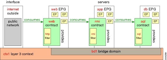
http のフィルタを作成するためのパラメータ
この例で http のフィルタを作成するためのパラメータは次のとおりです。
| パラメータ名 | http のフィルタ |
|---|---|
| Name |
http |
| Number of Entries |
2 |
| Entry Name |
Dport-80 Dport-443 |
| Ethertype |
IP |
| Protocol |
tcp tcp |
| Destination Port |
http https |
rmi および sql のフィルタを作成するためのパラメータ
この例で、rmi および sql のフィルタを作成するためのパラメータは次のとおりです。
| パラメータ名 | rmi のフィルタ | sql のフィルタ |
|---|---|---|
| Name |
rmi |
sql |
| Number of Entries |
1 |
1 |
| Entry Name |
Dport-1099 |
Dport-1521 |
| Ethertype |
IP |
IP |
| Protocol |
tcp |
tcp |
| Destination Port |
1099 |
1521 |
アプリケーション プロファイル データベースの例
この例のアプリケーション プロファイル データベースは次のとおりです。
| EPG | 提供するコントラクト | 使用するコントラクト |
|---|---|---|
| Web |
Web |
rmi |
| app |
rmi |
sql |
| db |
sql |
-- |
GUI を使用したフィルタの作成
3 種類のフィルタを作成します。 この例では、HTTP、RMI、SQL です。 この作業では、HTTP フィルタを作成する方法を示します。 他のフィルタを作成する作業も同じです。
テナント、ネットワーク、およびブリッジ ドメインが作成されていることを確認します。
| ステップ 1 |
メニュー バーで [TENANTS] を選択します。 [Navigation] ペインで、 を展開し、[Filters] を右クリックして、[Create Filter] をクリックします。
|
||
| ステップ 2 |
[Create Filter] ダイアログボックスで、次の操作を実行します。
|
||
| ステップ 3 | [Name] フィールドの [Entries] を展開します。 HTTPS を [Destination] ポートとして持つ別のエントリを追加するために、同じ手順を実行して [Update] をクリックします。 新しいフィルタ ルールが追加されます。 | ||
| ステップ 4 | 上と同じ手順で、「rmi および sql のフィルタを作成するためのパラメータ」に示されているパラメータを使用して、さらに 2 つのフィルタ(rmi と sql)を作成します。 |
GUI を使用したコントラクトの作成
| ステップ 1 | メニュー バーで、[TENANTS] と、操作するテナントの名前を選択します。 [Navigation] ペインで、 を展開します。 | ||
| ステップ 2 | を右クリックします。 | ||
| ステップ 3 |
[Create Contract] ダイアログボックスで、次の作業を実行します。
|
||
| ステップ 4 | [Create Contract Subject] ダイアログボックスで、[OK] をクリックします。 | ||
| ステップ 5 | この手順の各ステップに同様に従って、rmi 用と sql 用にさらに 2 つのコントラクトを作成します。 rmi コントラクトの場合には、rmi サブジェクトを、sql コントラクトの場合には、sql サブジェクトを選択します。 |
GUI を使用したアプリケーション プロファイルの作成
| ステップ 1 | メニュー バーで [TENANTS] を選択します。 [Navigation] ペインで、テナントを展開して、[Application Profiles] を右クリックし、[Create Application Profile] をクリックします。 |
| ステップ 2 | [Create Application Profile] ダイアログボックスで、[Name] フィールドに、アプリケーション プロファイル名(OnlineStore)を追加します。 |
GUI を使用した EPG の作成
| ステップ 1 |
[EPGs] を展開します。 [Create Application EPG] ダイアログボックスで、次の操作を実行します。
|
| ステップ 2 | [Create Application Profile] ダイアログボックスで、さらに 2 つの EPG 作成します。 3 つの EPG は、同じブリッジ ドメインおよびデータセンターの db、app、web とする必要があります。 |
GUI を使用したコントラクトの使用と提供
以前に作成したコントラクトを関連付けて、EPG 間のポリシー関係を作成することができます。
| ステップ 1 |
[Add Consumed Contract] ダイアログボックスが表示されます。 |
||
| ステップ 2 | [Name] フィールドで、ドロップダウン リストから、[sql] コントラクトを選択します。 [OK] をクリックします。 このステップによって、db EPG による sql コントラクトの提供と app EPG による sql コントラクトの使用が可能になります。 | ||
| ステップ 3 |
APIC GUI 画面上で app EPG をクリックして web EPG へドラッグします。 [Add Consumed Contract] ダイアログボックスが表示されます。 |
||
| ステップ 4 | [Name] フィールドで、ドロップダウン リストから、[rmi] コントラクトを選択します。 [OK] をクリックします。 このステップにより、app EPG が rmi コントラクトを提供し、web EPG が rmi コントラクトを使用できるようになります。 | ||
| ステップ 5 | web EPG のアイコンをクリックし、[Provided Contracts] 領域の [+] 記号をクリックします。 [Add Provided Contract] ダイアログボックスが表示されます。 | ||
| ステップ 6 | [Name] フィールドで、ドロップダウン リストから、[web] コントラクトを選択します。 [OK] をクリックします。 [Submit] をクリックします。 OnlineStore という名前の Three-Tier アプリケーション プロファイルを作成しました。 | ||
| ステップ 7 | 確認するには、[Navigation] ペインで、[Application Profiles] の下にある [OnlineStore] に移動してクリックします。 [Work] ペインに、app、db、web という 3 つの EPG が表示されていることを確認できます。 | ||
| ステップ 8 | [Work] ペインで、 を選択します。 EPG とコントラクトが使用および提供される順番で表示されます。 |
REST API を使用したアプリケーション ポリシーの導入
| ステップ 1 |
XML API を使用してアプリケーションを展開するため、この HTTP POST メッセージを送信します。 例: POST https://192.0.20.123/api/mo/uni/tn-ExampleCorp.xml |
| ステップ 2 |
POST メッセージの本文にこの XML 構造を含めます。 例: <fvTenant name="ExampleCorp"> <fvAp name="OnlineStore"> <fvAEPg name="web"> <fvRsBd tnFvBDName="bd1"/> <fvRsCons tnVzBrCPName="rmi"/> <fvRsProv tnVzBrCPName="web"/> <fvRsDomAtt tDn="uni/vmmp-VMware/dom-datacenter"/> </fvAEPg> <fvAEPg name="db"> <fvRsBd tnFvBDName="bd1"/> <fvRsProv tnVzBrCPName="sql"/> <fvRsDomAtt tDn="uni/vmmp-VMware/dom-datacenter"/> </fvAEPg> <fvAEPg name="app"> <fvRsBd tnFvBDName="bd1"/> <fvRsProv tnVzBrCPName="rmi"/> <fvRsCons tnVzBrCPName="sql"/> <fvRsDomAtt tDn="uni/vmmp-VMware/dom-datacenter"/> </fvAEPg> </fvAp> <vzFilter name="http" > <vzEntry dFromPort="80" name="DPort-80" prot="tcp" etherT="ip"/> <vzEntry dFromPort="443" name="DPort-443" prot="tcp" etherT="ip"/> </vzFilter> <vzFilter name="rmi" > <vzEntry dFromPort="1099" name="DPort-1099" prot="tcp" etherT="ip"/> </vzFilter> <vzFilter name="sql"> <vzEntry dFromPort="1521" name="DPort-1521" prot="tcp" etherT="ip"/> </vzFilter> <vzBrCP name="web"> <vzSubj name="web"> <vzRsSubjFiltAtt tnVzFilterName="http"/> </vzSubj> </vzBrCP> <vzBrCP name="rmi"> <vzSubj name="rmi"> <vzRsSubjFiltAtt tnVzFilterName="rmi"/> </vzSubj> </vzBrCP> <vzBrCP name="sql"> <vzSubj name="sql"> <vzRsSubjFiltAtt tnVzFilterName="sql"/> </vzSubj> </vzBrCP> </fvTenant> |
XML 構造内の最初の行は、ExampleCorp という名前のテナントを変更するか、必要に応じて作成します。
<fvTenant name="ExampleCorp">
この行は OnlineStore という名前のアプリケーション ネットワーク プロファイルを作成します。
<fvAp name="OnlineStore">
アプリケーション ネットワーク プロファイル内の要素は、3 台のサーバのそれぞれに 1 つずつで、3 つのエンドポイント グループを作成します。 以降の行は、web という名前のエンドポイント グループを作成し、既存の bd1 という名前のブリッジ ドメインに関連付けます。 このエンドポイント グループは、rmi という名前のバイナリ コントラクトによって許可されたトラフィックのコンシューマ、つまり宛先で、かつ、web というコントラクトによって許可されたトラフィックのプロバイダー、つまり発信元です。 エンドポイント グループは、datacenter という名前の VMM ドメインに関連付けられます。
<fvAEPg name="web">
<fvRsBd tnFvBDName="bd1"/>
<fvRsCons tnVzBrCPName="rmi"/>
<fvRsProv tnVzBrCPName="web"/>
<fvRsDomAtt tDn="uni/vmmp-VMware/dom-datacenter"/>
</fvAEPg>
残りの 2 つ、アプリケーション サーバとデータベース サーバのためのエンドポイント グループも同様の方法で作成されます。
以降の行は、HTTP(ポート 80)および HTTPS(ポート 443)という種類の TCP トラフィックを指定する、http という名前のトラフィック フィルタを定義します。
<vzFilter name="http" > <vzEntry dFromPort="80" name="DPort-80" prot="tcp" etherT="ip"/> <vzEntry dFromPort="443" name="DPort-443" prot="tcp" etherT="ip"/> </vzFilter>
残りの 2 つ、アプリケーション データおよびデータベース(sql)データのためのフィルタも同様の方法で作成されます。
以降の行は、http という名前のフィルタを取り込む web という名前のバイナリ コントラクトを作成します。
<vzBrCP name="web">
<vzSubj name="web">
<vzRsSubjFiltAtt tnVzFilterName="http"/>
</vzSubj>
</vzBrCP>
残り 2 つ、rmi および sql のデータ プロトコルのためのコントラクトも同様の方法で作成されます。
最後の行で構造を閉じます。
</fvTenant>
CLI を使用したアプリケーション ポリシーの導入
| ステップ 1 |
CLI で、ディレクトリを /aci に変更します。 例: admin@apic1:~> cd /aci |
| ステップ 2 |
テナントのアプリケーション ネットワーク プロファイルを作成します。 この例のアプリケーション ネットワーク プロファイルは OnlineStore です。 例: admin@apic1:aci> cd /aci/tenants/ExampleCorp/application-profiles/ admin@apic1:application-profiles> mocreate OnlineStore admin@apic1:application-profiles> moconfig commit Committing mo 'tenants/ExampleCorp/application-profiles/OnlineStore' All mos committed successfully. admin@apic1:application-profiles> |
| ステップ 3 |
テナントのアプリケーション ネットワーク プロファイルに関するアプリケーション Web、データベースとアプリケーション EPG を作成します。 例: admin@apic1:application-profiles> cd OnlineStore/ admin@apic1:OnlineStore> mocreate application-epg web admin@apic1:OnlineStore> mocreate application-epg db admin@apic1:OnlineStore> mocreate application-epg app admin@apic1:OnlineStore> moconfig commit Committing mo 'tenants/ExampleCorp/application-profiles/OnlineStore/application-epg-app' Committing mo 'tenants/ExampleCorp/application-profiles/OnlineStore/application-epg-db' Committing mo 'tenants/ExampleCorp/application-profiles/OnlineStore/application-epg-web' All mos committed successfully. admin@apic1:OnlineStore>
|
| ステップ 4 |
これらの EPG 間の各トラフィック タイプのフィルタを作成します。 例: admin@apic1:OnlineStore> cd /aci/tenants/ExampleCorp/security-policies/filters/ |
| ステップ 5 |
http および https のトラフィックのフィルタを作成します。 例: admin@apic1:filters> mocreate http admin@apic1:filters> moconfig commit Committing mo 'tenants/ExampleCorp/security-policies/filters/http' All mos committed successfully. admin@apic1:filters> admin@apic1:filters> cd http/entries/ admin@apic1:entries> mocreate DPort-80 ethertype ip admin@apic1:entries> cd DPort-80 admin@apic1:DPort-80> moset ip-protocol tcp admin@apic1:DPort-80> moset destination-port-dfromport 80 admin@apic1:DPort-80> moconfig commit Committing mo 'tenants/ExampleCorp/security-policies/filters/http/entries/DPort-80' All mos committed successfully. admin@apic1:DPort-80> cd ../ admin@apic1:entries> mocreate DPort-443 ethertype ip admin@apic1:entries> cd DPort-443 admin@apic1:DPort-443> moset ip-protocol tcp admin@apic1:DPort-443> moset destination-port-dfromport 443 admin@apic1:DPort-443> moconfig commit Committing mo 'tenants/ExampleCorp/security-policies/filters/http/entries/DPort-443' All mos committed successfully. admin@apic1:DPort-443> |
| ステップ 6 |
Remote Method Invocation (RMI)トラフィックのフィルタを作成します。 例: admin@apic1:~> cd /aci/tenants/ExampleCorp/security-policies/filters/ admin@apic1:filters> mocreate rmi admin@apic1:filters> moconfig commit Committing mo 'tenants/ExampleCorp/security-policies/filters/rmi' All mos committed successfully. admin@apic1:filters> cd rmi/entries/ admin@apic1:entries> mocreate DPort-1099 ethertype ip admin@apic1:entries> cd DPort-1099 admin@apic1:DPort-1099> moset ip-protocol tcp admin@apic1:DPort-1099> moset destination-port-dfromport 1099 admin@apic1:DPort-1099> moconfig commit Committing mo 'tenants/ExampleCorp/security-policies/filters/rmi/entries/DPort-1099' All mos committed successfully. admin@apic1:DPort-1099> |
| ステップ 7 |
SQL/database トラフィックのフィルタを作成します。 例: admin@apic1:DPort-1099> cd /aci/tenants/ExampleCorp/security-policies/filters/ admin@apic1:filters> mocreate sql admin@apic1:filters> moconfig commit Committing mo 'tenants/ExampleCorp/security-policies/filters/sql' All mos committed successfully. admin@apic1:filters> cd sql/entries/ admin@apic1:entries> mocreate DPort-1521 ethertype ip admin@apic1:entries> cd DPort-1521 admin@apic1:DPort-1521> moset ip-protocol tcp admin@apic1:DPort-1521> moset destination-port-dfromport 1521 admin@apic1:DPort-1521> moconfig commit Committing mo 'tenants/ExampleCorp/security-policies/filters/sql/entries/DPort-1521' All mos committed successfully. admin@apic1:DPort-1521> |
| ステップ 8 |
コントラクトを作成し、EPG 間の RMI トラフィックのフィルタを割り当てます。 例: admin@apic1:DPort-1521> admin@apic1:DPort-1521> cd /aci/tenants/ExampleCorp/security-policies/contracts/ admin@apic1:contracts> mocreate rmi admin@apic1:contracts> moconfig commit Committing mo 'tenants/ExampleCorp/security-policies/contracts/rmi' All mos committed successfully. admin@apic1:contracts> cd rmi/subjects/ admin@apic1:subjects> mocreate rmi admin@apic1:subjects> moconfig commit Committing mo 'tenants/ExampleCorp/security-policies/contracts/rmi/subjects/rmi' All mos committed successfully. admin@apic1:subjects> cd rmi/filters/ admin@apic1:filters> mocreate rmi admin@apic1:filters> moconfig commit Committing mo 'tenants/ExampleCorp/security-policies/contracts/rmi/subjects/rmi/filters/rmi' All mos committed successfully. admin@apic1:filters> |
| ステップ 9 |
コントラクトを作成し、EPG 間の web トラフィックのフィルタを割り当てます。 例: admin@apic1:filters> cd /aci/tenants/ExampleCorp/security-policies/contracts/ admin@apic1:contracts> mocreate web admin@apic1:contracts> moconfig commit Committing mo 'tenants/ExampleCorp/security-policies/contracts/web' All mos committed successfully. admin@apic1:contracts> cd web/subjects/ admin@apic1:subjects> mocreate web admin@apic1:subjects> moconfig commit Committing mo 'tenants/ExampleCorp/security-policies/contracts/web/subjects/web' All mos committed successfully. admin@apic1:subjects> cd web/filters/ admin@apic1:filters> mocreate http admin@apic1:filters> moconfig commit Committing mo 'tenants/ExampleCorp/security-policies/contracts/web/subjects/web/filters/http' All mos committed successfully. admin@apic1:filters> |
| ステップ 10 |
コントラクトを作成し、EPG 間の SQL トラフィックのフィルタを割り当てます。 例: admin@apic1:filters> cd /aci/tenants/ExampleCorp/security-policies/contracts/ admin@apic1:contracts> mocreate sql admin@apic1:contracts> moconfig commit Committing mo 'tenants/ExampleCorp/security-policies/contracts/sql' All mos committed successfully. admin@apic1:contracts> cd sql/subjects/ admin@apic1:subjects> mocreate sql admin@apic1:subjects> moconfig commit Committing mo 'tenants/ExampleCorp/security-policies/contracts/sql/subjects/sql' All mos committed successfully. admin@apic1:subjects> cd sql/filters/ admin@apic1:filters> mocreate sql admin@apic1:filters> moconfig commit Committing mo 'tenants/ExampleCorp/security-policies/contracts/sql/subjects/sql/filters/sql' All mos committed successfully. admin@apic1:filters> |
| ステップ 11 |
web EPG にブリッジ ドメイン、コントラクト、VMM ドメインをアタッチします。 例: admin@apic1:filters> cd /aci/tenants/ExampleCorp/application-profiles/OnlineStore/application-epg-web/ admin@apic1:application-epg-web> moset bridge-domain bd1 admin@apic1:application-epg-web> moconfig commit Committing mo 'tenants/ExampleCorp/application-profiles/OnlineStore/application-epg-web' All mos committed successfully. admin@apic1:application-epg-web> cd contracts/consumed-contracts/ admin@apic1:consumed-contracts> mocreate rmi admin@apic1:consumed-contracts> moconfig commit Committing mo 'tenants/ExampleCorp/application-profiles/OnlineStore/application-epg-web/contracts/consumed-contracts/rmi' All mos committed successfully. admin@apic1:consumed-contracts> cd ../provided-contracts/ admin@apic1:provided-contracts> mocreate web admin@apic1:provided-contracts> moconfig commit Committing mo 'tenants/ExampleCorp/application-profiles/OnlineStore/application-epg-web/contracts/provided-contracts/web' All mos committed successfully. admin@apic1:provided-contracts> cd ../../domains-vms-and-bare-metals/ admin@apic1:domains-vms-and-bare-metals> mocreate vm-networking/policies/VMware/vmm-domains/productionDC admin@apic1:domains-vms-and-bare-metals> moconfig commit Committing mo 'tenants/ExampleCorp/application-profiles/OnlineStore/application-epg-web/ domains-vms-and-bare-metals/[vm-networking/policies/vmware/vmm-domains/productionDC]' All mos committed successfully. admin@apic1:domains-vms-and-bare-metals> |
| ステップ 12 |
db EPG にブリッジ ドメイン、コントラクト、VMM ドメインをアタッチします。 例: admin@apic1:domains-vms-and-bare-metals> cd /aci/tenants/ ExampleCorp/application-profiles/application-profile-OnlineStore/application-epg-db/ admin@apic1:domains-vms-and-bare-metals> moset bridge-domain bd1 admin@apic1:domains-vms-and-bare-metals> moconfig commit Committed mo 'tenants/ExampleCorp/application-profiles/application-profile-OnlineStore/application-epg-sql' All mos committed successfully. admin@apic1:domains-vms-and-bare-metals> admin@apic1:domains-vms-and-bare-metals> cd /aci/tenants/ExampleCorp/application-profiles/ OnlineStore/application-epg-db/ admin@apic1:application-epg-db> moset bridge-domain bd1 admin@apic1:application-epg-db> moconfig commit Committing mo 'tenants/ExampleCorp/application-profiles/OnlineStore/application-epg-db' All mos committed successfully. admin@apic1:application-epg-db> cd contracts/provided-contracts/ admin@apic1:provided-contracts> mocreate sql admin@apic1:provided-contracts> moconfig commit Committing mo 'tenants/ExampleCorp/application-profiles/OnlineStore/application-epg-db/contracts/provided-contracts/sql' All mos committed successfully. admin@apic1:provided-contracts> cd ../../domains-vms-and-bare-metals/ admin@apic1:domains-vms-and-bare-metals> mocreate vm-networking/policies/VMware/vmm-domains/productionDC admin@apic1:domains-vms-and-bare-metals> moconfig commit Committing mo 'tenants/ExampleCorp/application-profiles/OnlineStore/application-epg-db/ domains-vms-and-bare-metals/[vm-networking/policies/vmware/vmm-domains/productionDC]' All mos committed successfully. admin@apic1:domains-vms-and-bare-metals> |
| ステップ 13 |
app EPG にブリッジ ドメイン、コントラクト、VMM ドメインをアタッチします。 例: admin@apic1:domains-vms-and-bare-metals> cd /aci/tenants/ ExampleCorp/application-profiles/OnlineStore/application-epg-app/ admin@apic1:application-epg-app> moset bridge-domain bd1 admin@apic1:application-epg-app> moconfig commit Committing mo 'tenants/ExampleCorp/application-profiles/OnlineStore/application-epg-app' All mos committed successfully. |
| ステップ 14 |
app EPG アプリケーションにプロバイダー コントラクトを関連付けます。 例: admin@apic1:application-epg-app> cd contracts/provided-contracts/ admin@apic1:provided-contracts> mocreate rmi admin@apic1:provided-contracts> moconfig commit Committing mo 'tenants/ExampleCorp/application-profiles/OnlineStore/application-epg-app/contracts/provided-contracts/rmi' All mos committed successfully. admin@apic1:provided-contracts> cd ../consumed-contracts/ admin@apic1:consumed-contracts> mocreate sql admin@apic1:consumed-contracts> moconfig commit Committing mo 'tenants/ExampleCorp/application-profiles/OnlineStore/application-epg-app/contracts/consumed-contracts/sql' All mos committed successfully. admin@apic1:consumed-contracts> cd ../../domains-vms-and-bare-metals/ admin@apic1:domains-vms-and-bare-metals> mocreate vm-networking/policies/VMware/vmm-domains/productionDC admin@apic1:domains-vms-and-bare-metals> moconfig commit Committing mo 'tenants/ExampleCorp/application-profiles/OnlineStore/application-epg-app/domains-vms-and-bare-metals/ [vm-networking/policies/vmware/vmm-domains/productionDC]' All mos committed successfully. admin@apic1:domains-vms-and-bare-metals> |
| ステップ 15 |
app、db、web という EPG にポートと VLAN を関連付けます。 例: admin@apic1:domains-vms-and-bare-metals> cd /aci/tenants/ExampleCorp/ application-profiles/OnlineStore/application-epg-app/static-bindings-paths/ admin@apic1:static-bindings-paths> mocreate topology/pod-1/paths-17/ pathep-[eth1/2] encap vlan-100 deployment-immediacy immediate admin@apic1:static-bindings-paths> moconfig commit Committing mo 'tenants/ExampleCorp/application-profiles/OnlineStore/application-epg-app/static-bindings-paths/ [topology/pod-1/paths-17/pathep-[eth1/2]]' All mos committed successfully. admin@apic1:static-bindings-paths> admin@apic1:static-bindings-paths> cd /aci/tenants/ExampleCorp/application-profiles/OnlineStore/application-epg-db/ static-bindings-paths/ admin@apic1:static-bindings-paths> mocreate topology/pod-1/paths-17/ pathep-[eth1/3] encap vlan-101 deployment-immediacy immediate admin@apic1:static-bindings-paths> moconfig commit Committing mo 'tenants/ExampleCorp/application-profiles/OnlineStore/application-epg-db/static-bindings-paths/ [topology/pod-1/paths-17/pathep-[eth1/3]]' All mos committed successfully. admin@apic1:static-bindings-paths> admin@apic1:static-bindings-paths> cd /aci/tenants/ExampleCorp/application-profiles/OnlineStore/ application-epg-web/static-bindings-paths/ admin@apic1:static-bindings-paths> mocreate topology/pod-1/paths-17/ pathep-[eth1/4] encap vlan-102 deployment-immediacy immediate admin@apic1:static-bindings-paths> moconfig commit Committing mo 'tenants/ExampleCorp/application-profiles/OnlineStore/application-epg-web/static-bindings-paths/ [topology/pod-1/paths-17/pathep-[eth1/4]]' All mos committed successfully. admin@apic1:static-bindings-paths> |
目次
- 使用する前に
- 初回アクセス
- Cisco Application Centric Infrastructure ファブリック ハードウェアのインストール
- APIC コントローラの BIOS デフォルト パスワードの変更
- APIC について
- APIC のセットアップ
- GUI へのアクセス
- REST API へのアクセス
- CLI へのアクセス
- GUI の概要
- GUI の概要
- メニュー バーおよびサブメニュー バー
- [SYSTEM] タブ
- [TENANTS] タブ
- [FABRIC] タブ
- [VM NETWORKING] タブ
- [L4-L7 SERVICES] タブ
- [ADMIN] タブ
- [Search] アイコン
- [Navigation] ペイン
- [Work] ペイン
- GUI アイコン
- エラー、統計情報およびヘルス レベルのアイコン
- APIC の例について
- ファブリックの初期設定
- ファブリックの初期設定について
- トポロジの例
- トポロジの接続の例
- APIC によるスイッチの検出
- APIC クラスタへのスイッチの登録
- APIC によるスイッチ検出の検証およびスイッチ管理
- ファブリック トポロジの検証
- VM 管理のアンマネージド スイッチの接続
- スイッチの登録
- GUI を使用した未接続スイッチの登録
- REST API を使用した未接続スイッチの登録
- CLI を使用した未接続スイッチの登録
- スイッチの検証
- GUI を使用した接続済みスイッチの登録
- REST API を使用した接続済みスイッチの登録
- CLI を使用した接続済みスイッチの登録
- ファブリック トポロジの検証
- GUI を使用したファブリック トポロジの検証
- REST API を使用したファブリック トポロジの検証
- ユーザ アカウントの作成
- ローカル ユーザの設定
- リモート ユーザの設定
- GUI を使用したローカル ユーザの設定
- REST API を使用したローカル ユーザの設定
- CLI を使用したローカル ユーザの設定
- 外部認証サーバの AV ペア
- 外部認証サーバの AV ペアの設定
- GUI を使用したリモート ユーザの設定
- REST API を使用したリモート ユーザの設定
- CLI を使用したリモート ユーザの設定
- 管理アクセスの追加
- インバンドおよびアウトオブバンド管理アクセスの設定
- GUI を使用したインバンド管理アクセスの設定
- REST API を使用したインバンド管理アクセスの設定
- CLI を使用したインバンド管理アクセスの設定
- GUI を使用したアウトオブバンド管理アクセスの設定
- REST API を使用したアウトオブバンド管理アクセスの設定
- CLI を使用したアウトオブバンド管理アクセスの設定
- GUI を使用した APIC コントローラの IP アドレスの変更
- REST API を使用した APIC コントローラの IP アドレスの変更
- CLI を使用した APIC コントローラの IP アドレスの変更
- 管理接続モード
- GUI を使用したレイヤ 2 管理接続の設定
- REST API を使用したレイヤ 2 管理接続の設定
- CLI を使用したレイヤ 2 管理接続の設定
- GUI を使用したレイヤ 3 管理接続の設定
- REST API を使用したレイヤ 3 管理接続の設定
- CLI を使用したレイヤ 3 管理接続の設定
- 管理接続の検証
- VM 管理システムの接続
- 仮想マシンのネットワーキング ポリシーの設定
- VM 管理システムについて
- 接続可能エンティティ プロファイルについて
- VMM ドメイン プロファイルの作成
- VMM ドメイン プロファイルを作成するための前提条件
- GUI を使用した vCenter ドメイン プロファイルの作成
- REST API を使用した vCenter ドメイン プロファイルの作成
- CLI を使用した vCenter ドメイン プロファイルの作成
- GUI を使用した vCenter および vShield ドメイン プロファイルの作成
- REST API を使用した vCenter および vShield のドメイン プロファイルの作成
- CLI を使用した vCenter および vShield ドメイン プロファイルの作成
- テナント、プライベート ネットワーク、およびブリッジ ドメインの作成
- テナントの概要
- テナントの作成
- ネットワークおよびブリッジ ドメイン
- GUI を使用した、テナント、プライベート ネットワーク、およびブリッジ ドメインの作成
- REST API を使用した、テナント、プライベート ネットワーク、およびブリッジ ドメインの作成
- CLI を使用した、テナント、プライベート ネットワーク、およびブリッジ ドメインの作成
- サーバ ポリシーまたはサービス ポリシーの設定
- DHCP リレー ポリシーの設定
- GUI を使用した、APIC インフラストラクチャ用 DHCP サーバ ポリシーの設定
- REST API を使用した APIC インフラストラクチャの DHCP サーバ ポリシーの設定
- CLI を使用した APIC インフラストラクチャの DHCP サーバ ポリシーの設定
- DNS サービス ポリシーの設定
- インバンド DNS サービス ポリシーによる外部接続先の設定
- GUI を使用した、DNS プロバイダーと接続するための DNS サービス ポリシーの設定
- REST API を使用した、DNS プロバイダーと接続するための DNS サービス ポリシーの設定
- CLI を使用した、DNS プロバイダーと接続するためのDNS サービス ポリシーの設定
- CLI を使用した、DNS プロファイルがファブリック コントローラ スイッチに設定および適用されていることの確認
- テナント用外部接続の設定
- GUI を使用した MP-BGP ルート リフレクタの設定
- REST API を使用した MP-BGP ルート リフレクタの設定
- CLI を使用した MP-BGP ルート リフレクタの設定
- MP-BGP ルート リフレクタの設定の確認
- GUI を使用した、管理テナント用 OSPF 外部ルーテッド ネットワークの作成
- REST API を使用した、管理テナント用 OSPF 外部ルーテッド ネットワークの作成
- CLI を使用した、管理テナント用 OSPF 外部ルーテッド ネットワークの作成
- アプリケーション ポリシーの導入
- Three-Tier アプリケーションの展開
- http のフィルタを作成するためのパラメータ
- rmi および sql のフィルタを作成するためのパラメータ
- アプリケーション プロファイル データベースの例
- GUI を使用したアプリケーション ポリシーの導入
- GUI を使用したフィルタの作成
- GUI を使用したコントラクトの作成
- GUI を使用したアプリケーション プロファイルの作成
- GUI を使用した EPG の作成
- GUI を使用したコントラクトの使用と提供
- REST API を使用したアプリケーション ポリシーの導入
- CLI を使用したアプリケーション ポリシーの導入
この章の内容は、次のとおりです。
- 初回アクセス
- GUI の概要
- APIC の例について
- ファブリックの初期設定
- ユーザ アカウントの作成
- 管理アクセスの追加
- VM 管理システムの接続
- テナント、プライベート ネットワーク、およびブリッジ ドメインの作成
- サーバ ポリシーまたはサービス ポリシーの設定
- テナント用外部接続の設定
- アプリケーション ポリシーの導入
Cisco Application Centric Infrastructure ファブリック ハードウェアのインストール
ACI ファブリック ハードウェアのインストールの詳細については、『Application Centric Infrastructure Fabric Hardware Installation Guide』を参照してください。
APIC コントローラの BIOS デフォルト パスワードの変更
手順APIC コントローラには、デフォルト BIOS パスワードが付属しています。 デフォルトのパスワードは "password" です。 APIC コントローラがブート プロセスを開始すると、ブート画面にコンソール サーバの BIOS 情報が表示されます。
デフォルト BIOS パスワードを変更するには、次の作業を実行します。
ステップ 1 BIOS のブート プロセス中、画面に「Press <F2> Setup」と表示されたときに、F2 キーを押します。 「Entering Setup」というメッセージが表示されて、メニューにアクセスします。 ステップ 2 [Enter Password] ダイアログボックスに、現在のパスワードを入力します。
(注) デフォルトは "password" です。
ステップ 3 [Setup Utility] で、[Security] タブを選択し、[Set Administrator Password] を選択します。 ステップ 4 [Enter Current Password] ダイアログボックスに、現在のパスワードを入力します。 ステップ 5 [Create New Password] ダイアログボックスに、新しいパスワードを入力します。 ステップ 6 [Confirm New Password] ダイアログボックスに、新しいパスワードをもう一度入力します。 ステップ 7 [Save & Exit] タブを選択します。 ステップ 8 [Save & Exit Setup] ダイアログボックスで、[Yes] を選択します。 ステップ 9 APIC コントローラが再起動プロセスを完了するのを待ちます。 更新された BIOS パスワードが有効になります。
APIC について
Cisco Application Centric Infrastructure(ACI)は、外部エンドポイントの接続性がアプリケーション セントリック ポリシーを通じて制御されグループ化された分散型のスケーラブルなマルチテナント インフラストラクチャです。 Application Policy Infrastructure Controller(APIC)は、ACI の自動化、管理、モニタリングおよびプログラマビリティの統合ポイントです。 APICは、インフラストラクチャの物理/仮想コンポーネント用の統合操作モデルを使用して、アプリケーションの展開、管理、およびモニタリングをあらゆる場所でサポートします。 APICは、アプリケーションの要件とポリシーに基づき、ネットワークのプロビジョニングおよび制御をプログラムで自動化します。 また、これは幅広いクラウド ネットワークに対する中央制御エンジンなので、管理が容易になり、アプリケーション ネットワークの定義および自動化の方法に柔軟性が得られます。 また、ノースバウンド Representational State Transfer(REST)API が提供されます。 APICは、多くのコントローラ インスタンスのクラスタとして実装される分散システムです。
APIC のセットアップ
APIC の初回起動時には、APIC コンソールに一連の初期設定オプションが表示されます。 多くのオプションでは、Enter を押して大カッコ内に表示されたデフォルト設定を選択することができます。 初期設定ダイアログの任意の時点で、Ctrl+C キーを押してダイアログを最初から再開できます。
名前 説明 デフォルト値 ファブリック名
ファブリックのドメイン名
ACI Fabric 1
コントローラ数
クラスタ サイズ
3
コントローラの ID
APIC インスタンスの一意の ID 番号
1、2、または 3
トンネル エンドポイント アドレス用の IP アドレス プール
トンネル エンドポイント アドレス プール
10.0.0.0/16
この値はインフラストラクチャの 仮想ルーティングおよび転送(VRF)専用です
ブリッジ ドメインのマルチキャスト アドレス(GIPO)の IP アドレス プール
ファブリック マルチキャストに使用する IP アドレス
225.0.0.0/15
有効な範囲:225.0.0.0/15 ~ 231.254.0.0/15、prefixlenは 15 である必要があります(128k IPs)
管理インターフェイスの速度およびデュプレックス モード
アウトオブバンド管理インターフェイスのインターフェイス速度とデュプレックス モード
auto
インフラストラクチャ ネットワークの VLAN ID
仮想スイッチを含む APIC スイッチ間の通信用インフラストラクチャ VLAN
(注) この VLAN を APIC 専用に予約します。 4093
アウトオブバンド管理用の IP アドレス
GUI、CLI、または API を通じて APIC にアクセスするのに使用する IP アドレス
このアドレスは、お客様のプライベート ネットワークからの予約アドレスである必要があります。
—
デフォルト ゲートウェイの IP アドレス。
外部ネットワークへのアウトオブバンド管理を使用した通信のゲートウェイ アドレス
—
パスワードの強度の確認
強力なパスワードであることを確認してください。
Y
パスワード
システム管理者のパスワード
このパスワードは 1 つの特殊文字を含む 8 文字以上にする必要があります。
—
以下は、コンソールに表示される初期設定ダイアログの例です。Cluster configuration ... Enter the fabric name [ACI Fabric1 #1]: Enter the number of controllers in the fabric (1-16) [3]: Enter the controller ID (1-3) [2]: Enter the controller name [apic2]: Enter address pool for TEP addresses [10.0.0.0/16]: Enter the VLAN ID for infra network (1-4094)[4093]: <<< This is for the physical APIC Enter the VLAN ID for infra network (1-4094) [4]: <<< This is for the Simulator Enter address pool for BD multicast addresses (GIPO) [225.0.0.0/15]: Out-of-band management configuration ... Enter the IP address for out-of-band management: 192.168.10.2/24 Enter the IP address of the default gateway [None]: 192.168.10.254 Enter the interface speed/duplex mode [auto]: Administrator user configuration... Enable strong passwords? [Y] Enter the password for admin:
GUI へのアクセス
手順
ステップ 1 サポートされているブラウザの 1 つを開きます。
Chrome 29(またはそれ以降のバージョン)
(注) https サイトにアクセスするときには、有効な証明書をインストールすることが推奨されます。 証明書が無署名の場合は [Safari can't verify the identify of the website "local host"] ダイアログボックスが表示されます。 [Continue] はクリックしないでください。 [Show Certificate] を選択します。 [Trust] セクションを拡張し、[Always Trust] を選択します。 パスワードを入力し、[Continue] をクリックします。
Firefox 24(またはそれ以降のバージョン)
Internet Explorer 10(それ以降のバージョン)
ステップ 2 URL を入力します。https://mgmt_ip-address 初期設定時に設定したアウトオブバンド管理の IP アドレスを使用します。 たとえば、https://192.168.10.1 と入力します。
(注) https だけがデフォルトでイネーブルになっています。 デフォルトでは、http および http から https へのリダイレクトはディセーブルになります。
ステップ 3 ログイン画面が表示されたときは、初期設定時に設定した管理者名とパスワードでログインします。
次の作業
アプリケーション セントリック インフラストラクチャ ファブリック および Application Policy Infrastructure Controller の機能と運用については、提供されているホワイト ペーパーおよび 『Cisco Application Centric Infrastructure Fundamentals Guide』を参照してください。
REST API へのアクセス
CLI へのアクセス
手順
ステップ 1 セキュア シェル(SSH)クライアントから、admin@ip-address への SSH 接続を開きます。 初期設定時に設定したアウトオブバンド管理 IP アドレスと管理者のログイン名を使用します。 たとえば、admin@192.168.10.1 と指定します。
ステップ 2 プロンプトが表示されたら、初期設定時に設定した管理者のパスワードを入力します。
次の作業
すべてのユーザは /home と呼ばれる共有ディレクトリを使用する必要があります。 このディレクトリでは、ディレクトリとファイルを作成できる権限がユーザに与えられます。/home 内で作成されるファイルはデフォルトの umask 権限を継承し、そのユーザと root がアクセスできます。 初めてログインしたときに、ファイル保管用にディレクトリを /home/userid という形式(/home/jsmith など)で作成することを推奨します。
ACI CLI を BASH または VSH などの動作モードで使用した場合のスイッチへのアクセスに関する詳細情報については、『Cisco APIC Command Line Interface User Guide』および『Cisco ACI Switch Command Reference』を参照してください。
APIC CLI の設定の詳細については、『Cisco APIC Command Line Interface User Guide』 を参照してください。
GUI の概要
APIC GUI は REST API メッセージの交換によって内部的に APICエンジンと通信するブラウザ ベースの APIC 用グラフィカル インターフェイスです。 GUI には複数のエリアおよびペインが含まれます。
メニュー バーおよびサブメニュー バー
- [SYSTEM] タブ
- [TENANTS] タブ
- [FABRIC] タブ
- [VM NETWORKING] タブ
- [L4-L7 SERVICES] タブ
- [ADMIN] タブ
- [Search] アイコン
- [Navigation] ペイン
- [Work] ペイン
[TENANTS] タブ
テナント管理の実行にメニュー バーの [TENANTS] タブを使用します。 サブメニュー バーに、[Add Tenant] リンクと、すべてのテナントを含むドロップダウン リストが表示されます。 最大 5 つまでの最近使用されたテナントもサブメニュー バーに表示されます。
テナントには、承認されたユーザのドメインベースのアクセス コントロールをイネーブルにするポリシーが含まれます。 承認されたユーザは、テナント管理やネットワーキング管理などの権限にアクセスできます。
ユーザは、ドメイン内のポリシーにアクセスしたりポリシーを設定するには読み取り/書き込み権限が必要です。 テナント ユーザは、1 つ以上のドメインに特定の権限を持つことができます。
マルチテナント環境では、リソースがそれぞれ分離されるように、テナントによりグループ ユーザのアクセス権限が提供されます(エンドポイント グループやネットワーキングなどのため)。 これらの権限では、異なるユーザが異なるテナントを管理することもできます。
[Navigation] ペイン
サブメニュー カテゴリのすべての要素に移動するには、APIC GUI の左側、サブメニュー バーのすぐ下の [Navigation] ペインを使用します。 [Navigation] ペインでコンポーネントを選択すると、そのオブジェクトが [Work] ペインに表示されます。
[Work] ペイン
APIC GUI の右側にある [Work] ペインに、[Navigation] ペインで選択したコンポーネントに関する詳細が表示されます。 [Work] ペインの表示例については、次の図を参照してください。
[Work] ペインは、次の要素で構成されます。
GUI アイコン
表 1 APIC GUIによく表示されるアイコン アイコン 説明

[Navigation] ペインの表示のコントロール矢印

[Work] ペインの最下部のコンテキスト ヘルプを表示または非表示にします

テーブルを XML ファイルとしてダウンロードします

[Navigation] ペインで選択したコンポーネントのグラフィック ビューが表示されます

[Navigation] ペインで選択したコンポーネントのグラフィック ビューが表示されます

パネルの状況を更新します。 リポジトリが変わるたびにデータが更新されるため、接続の問題がある場合にのみ、このアイコンをクリックします

オンライン ヘルプ情報を表示します

設定

次のビュー

前のビュー

パスを表示します

パスをクリアします
ファブリックの初期設定について
APIC によって管理するスイッチを追加し、GUI、CLI、または API を使用して手順を検証することによってファブリックを構築できます。
(注)
ファブリックを構築するには、事前にアウトオブバンド ネットワーク経由で APIC クラスタを作成しておく必要があります。
トポロジの例
トポロジ例は次のとおりです。
次の図は、ファブリック トポロジの例を示します。
トポロジの接続の例
トポロジの接続の例の詳細は次のとおりです。
名前 Connection Details leaf1
eth1/1 = apic1(eth2/1)
eth1/2 = apic2(eth2/1)
eth1/3 = apic3(eth2/1)
eth1/49 = spine1(eth5/1)
eth1/50 = spine2(eth5/2)
leaf2
eth1/1 = apic1(eth2/2)
eth1/2 = apic2(eth2/2)
eth1/3 = apic3(eth2/2)
eth1/49 = spine1(eth5/1)
eth1/50 = spine2(eth5/2)
spine1
eth5/1 = leaf1(eth1/49)
eth5/2 = leaf2(eth1/50)
spine2
eth5/1 = leaf2(eth1/49)
eth5/2 = leaf1(eth1/50)
APIC によるスイッチの検出
APIC は、ACI ファブリックに含まれるすべてのスイッチに対する自動プロビジョニングおよび管理の中心となるポイントです。 単一のデータセンターには複数のファブリック ACI がある場合があります。各データセンターには、独自の APIC クラスタとファブリックを構成する Cisco Nexus 9000 スイッチ シリーズがある場合があります。 スイッチが単一の APIC クラスタだけで管理されることを保証するには、各スイッチをファブリックを管理するその特定の APIC クラスタに登録する必要があります。
APIC は現在管理している任意のスイッチに直接接続された新規スイッチを検出します。 クラスタの各 APIC インスタンスは、最初に直接接続されたリーフ スイッチだけを検出します。 リーフ スイッチが APIC に登録されると、APIC はリーフ スイッチに直接接続されているすべてのスパイン スイッチを検出します。 各スパイン スイッチが登録されるごとに、APIC はそのスパイン スイッチに接続されているすべてのリーフ スイッチを検出します。 この段階的な検出方法により、APIC は簡単な手順でファブリック全体のトポロジを検出できます。
APIC クラスタへのスイッチの登録
(注)
スイッチの登録を開始する前に、ファブリック内のすべてのスイッチが物理的に接続され、必要な設定で起動されていることを確認します。 APIC を使用してスイッチを登録する際には「GUI を使用した未接続スイッチの登録」を参照してください。 シャーシの設置については、http://www.cisco.com/en/US/products/ps13386/prod_installation_guides_list.htmlを参照してください。
スイッチが APIC に登録されると、そのスイッチは、APIC 管理対象のファブリック インベントリの一部になります。 アプリケーション セントリック インフラストラクチャ ファブリック(ACI ファブリック)の場合、APIC はインフラストラクチャのスイッチのプロビジョニング、管理、および監視を一元化します。
(注)
インフラストラクチャの IP アドレス範囲は、インバンドおよびアウトオブバンドのネットワーク用の ACI ファブリックで使用する他の IP アドレスと重複してはなりません。
APIC によるスイッチ検出の検証およびスイッチ管理
スイッチが APIC に登録された後、APIC は自動的にファブリック トポロジを認識し、ネットワーク全体を把握してファブリック トポロジ内のすべてのスイッチを管理します。
個々のスイッチにアクセスすることなく、APIC から各スイッチの設定、監視、およびアップグレードができます。
VM 管理のアンマネージド スイッチの接続
VM コントローラ(vCenter など)で管理されているホストはレイヤ 2 スイッチを介してリーフ ポートに接続できます。 必要な唯一の前提条件は、レイヤ 2 スイッチに管理アドレスを設定すること、および、この管理アドレスがスイッチに接続されたポートに Link Layer Discovery Protocol(LLDP)または Cisco Discovery Protocol(CDP)によってアドバタイズされる必要があるということです。 レイヤ 2 スイッチは、 APIC によって自動的に検出され、管理アドレスで識別されます。 次の図は、 のビューでアンマネージド スイッチを表示している APIC GUI の一例です。GUI を使用した未接続スイッチの登録
手順
(注)
インフラストラクチャの IP アドレス範囲は、インバンドおよびアウトオブバンドのネットワーク用の ACI ファブリックで使用する他の IP アドレスと重複してはなりません。
(注)
このタスク例のビデオを視聴するには、Videos Webpage を参照してください。
ステップ 1 メニュー バーで、 を選択します。 ステップ 2 [Navigation] ペインで、適切なポッドを選択してポッドを展開し、[Fabric Membership] をクリックします。 [Work] ペインで、[Fabric Membership] テーブルに、単一の リーフ スイッチ が ID 0 とともに表示されます。 apic1 に接続されている リーフ スイッチ です。 ステップ 3 リーフ スイッチ の行をダブルクリックし、次の操作を実行して ID を設定します。 [Success] ダイアログボックスが表示されます。 IP アドレスがスイッチに割り当てられ、[Navigation] ペインのポッドの下にスイッチが表示されます。
ステップ 4 1 つ以上の スパイン スイッチ が表示されるまで [Work] ペインを監視します。 ステップ 5 スパイン スイッチ の行をダブルクリックして ID を設定し、次の操作を実行します。 [Success] ダイアログボックスが表示されます。 IP アドレスがスイッチに割り当てられ、[Navigation] ペインにスイッチがポッドの下に表示されます。 次の手順に進む前に、残りのすべてのスイッチが [Node Configurations] テーブルに表示されるまで待ちます。
ステップ 6 [Fabric Membership] テーブルに表示されているスイッチごとに次の手順を実行します。
REST API を使用した未接続スイッチの登録
手順
例:POST: https://apic_ip_address/api/node/mo/uni/controller.xml <fabricNodeIdentPol> <fabricNodeIdentP serial="FGE173900ZD" name="leaf1" nodeId="101"/> <fabricNodeIdentP serial="FGE1740010A" name="leaf2" nodeId="102"/> <fabricNodeIdentP serial="FGE1740010H" name="spine1" nodeId="103"/> <fabricNodeIdentP serial="FGE1740011B" name="spine2" nodeId="104"/> </fabricNodeIdentPol>CLI を使用した未接続スイッチの登録
手順
ステップ 1 CLI で、ディレクトリを /aci に変更します。
例:admin@apic1:~> cd /aciステップ 2 スイッチを登録します。
例:admin@apic1:fabric-membership> cd /aci/fabric/inventory/fabric-membership/node-policies admin@apic1:node-policies mocreate FGE173900ZD id 101 name leaf1 admin@apic1:node-policies moconfig commitステップ 3 他のスイッチに対して上記の手順を繰り返します(スイッチ 102、103、104 など)。
GUI を使用した接続済みスイッチの登録
手順
(注)
このタスク例のビデオを視聴するには、Videos Webpage を参照してください。
ステップ 1 メニュー バーで、 を選択します。 ステップ 2 [Navigation] ペインで、[Pod 1] の下の [Fabric Membership] を展開します。 ファブリック内のスイッチは、ノード ID とともに表示されます。 [Work] ペインに、登録されているすべてのスイッチが、割り当てられた IP アドレスとともに表示されます。
REST API を使用した接続済みスイッチの登録
手順
例:GET: https://<apic-ip>/api/node/class/topSystem.xml? <?xml version="1.0" encoding="UTF-8"?> <imdata> <topSystem address="10.0.0.1" dn="topology/pod-1/node-1/sys" fabricId="1" id="1" name="apic1" oobMgmtAddr="10.30.13.44" podId="1" role="apic" serial="" state="in-service" systemUpTime="00:00:00:02.199" .../> <topSystem address="10.0.0.2" dn="topology/pod-1/node-2/sys" fabricId="1" id="2" name="apic2" oobMgmtAddr="10.30.13.45" podId="1" role="apic" serial="" state="in-service" systemUpTime="00:00:00:02.199" .../> <topSystem address="10.0.0.3" dn="topology/pod-1/node-3/sys" fabricId="1" id="3" name="apic3" oobMgmtAddr="10.30.13.46" podId="1" role="apic" serial="" state="in-service" systemUpTime="00:00:00:02.199" .../> <topSystem address="10.0.98.127" dn="topology/pod-1/node-101/sys" fabricId="1" id="101" name="leaf1" oobMgmtAddr="0.0.0.0" podId="1" role="leaf" serial="FOX-270308" state="in-service" systemUpTime="00:00:00:02.199" .../> <topSystem address="10.0.98.124" dn="topology/pod-1/node-102/sys" fabricId="1" id="102" name="leaf2" oobMgmtAddr="0.0.0.0" podId="1" role="leaf" serial="FOX-270308" state="in-service" systemUpTime="00:00:00:02.199" .../> <topSystem address="10.0.98.125" dn="topology/pod-1/node-103/sys" fabricId="1" id="103" name="spine2" oobMgmtAddr="0.0.0.0" podId="1" role="spine" serial="FOX-616689" state="in-service" systemUpTime="00:00:00:02.199" .../> <topSystem address="10.0.98.126" dn="topology/pod-1/node-104/sys" fabricId="1" id="104" name="spine1" oobMgmtAddr="0.0.0.0" podId="1" role="spine" serial="FOX-616689" state="in-service" systemUpTime="00:00:00:02.199" .../> </imdata>CLI を使用した接続済みスイッチの登録
手順
ステップ 1 CLI で、ディレクトリを /aci に変更します。
例:admin@apic1:~> cd /aciステップ 2 スイッチの登録を検証します。
例:admin@apic1:pod-1> cat node-101/summary id : 101 name : leaf1 tags : topology/pod-1/node-101 admin-state : on alias : model : N9K-C9396TX vendor : Cisco Systems, Inc revision : 0.1.6 serial : FGE173900ZD up-time : 00:07:50:32.000 infra-ip : 10.0.36.95 in-band-management-ip : 0.0.0.0 out-of-band-management-ip : 0.0.0.0 top-system-name : leaf1 type : leaf health-score : topology/pod-1/node-101/sys firmware : simsw-1.0(0.552)
GUI を使用したファブリック トポロジの検証
手順
(注)
このタスク例のビデオを視聴するには、Videos Webpage を参照してください。
ステップ 1 メニュー バーで、 を選択します。 ステップ 2 [Navigation] ペインで、表示したいポッドを選択します。 ステップ 3 [Work] ペインで、[TOPOLOGY] タブをクリックします。 表示される図には、すべての接続されたスイッチ、APIC インスタンス、およびリンクが示されます。 ステップ 4 (任意) リーフ スイッチ または スパイン スイッチ のポート レベルでの接続を表示するには、トポロジ図の当該アイコンをダブルクリックします。
トポロジ図に戻るには、[Work] ペインの左上隅にある [Previous View] アイコンをクリックします。ステップ 5 (任意) トポロジ図を更新するには、[Work] ペインの左上隅にある [Refresh] アイコンをクリックします。
REST API を使用したファブリック トポロジの検証
手順
例:ユーザ参照用の識別子は次のとおりです。
n1 = 1 番目のノードの識別子
s1 = 1 番目のノードのスロット
p1 = スロット s1 のポート
n2 = 2 番目のノードの識別子
s2 = 2 番目のノードのスロット
p2 = スロット s2 のポート
GET: https://<apic-ip>/api/node/class/fabricLink.xml? <?xml version="1.0" encoding="UTF-8"?> <imdata> <fabricLink dn="topology/lnkcnt-19/lnk-18-1-50-to-19-5-2" n1="18" n2="19" p1="50" p2="2" s1="1" s2="5" status="" .../> <fabricLink dn="topology/lnkcnt-20/lnk-18-1-49-to-20-5-1" n1="18" n2="20" p1="49" p2="1" s1="1" s2="5" status="" .../> <fabricLink dn="topology/lnkcnt-3/lnk-18-1-1-to-3-1-1" n1="18" n2="3" p1="1" p2="1" s1="1" s2="1" status="" .../> <fabricLink dn="topology/lnkcnt-19/lnk-17-1-49-to-19-5-1" n1="17" n2="19" p1="49" p2="1" s1="1" s2="5" status="" .../> <fabricLink dn="topology/lnkcnt-20/lnk-17-1-50-to-20-5-2" n1="17" n2="20" p1="50" p2="2" s1="1" s2="5" status="" .../> <fabricLink dn="topology/lnkcnt-1/lnk-17-1-1-to-1-1-1" n1="17" n2="1" p1="1" p2="1" s1="1" s2="1" status="" .../> <fabricLink dn="topology/lnkcnt-2/lnk-17-1-2-to-2-1-1" n1="17" n2="2" p1="2" p2="1" s1="1" s2="1" status="" .../> </imdata>ローカル ユーザの設定
初期設定スクリプトで、管理者アカウントが設定され、システムの起動時には admin が唯一のユーザです。 APIC は、きめ細かなロール ベースのアクセス制御システムをサポートしており、権限の少ない非管理者ユーザなど、さまざまなロールのユーザ アカウントを作成できます。
GUI を使用したローカル ユーザの設定
手順
(注)
このタスク例のビデオを視聴するには、Videos Webpage を参照してください。
ステップ 1 メニュー バーで、 を選択します。 ステップ 2 [Navigation] ペインで、[AAA Authentication] をクリックします。 ステップ 3 [Work] ペインで、デフォルトの [Authentication] フィールドの [Relam] フィールドに Local と表示されていることを確認します。 ステップ 4 [Navigation] ペインで、 を展開します。 admin ユーザはデフォルトで存在します。
ステップ 5 [Navigation] ペインで、[Create Local User] を右クリックします。 ステップ 6 [Security] ダイアログボックスで、ユーザに必要なセキュリティ ドメインを選択し、[Next] をクリックします。 ステップ 7 [Roles] ダイアログボックスで、オプション ボタンをクリックしてユーザのロールを選択し、[Next] をクリックします。 読み取り専用、または読み取り/書き込み権限を付与できます。
ステップ 8 [User Identity] ダイアログボックスで、次の操作を実行します。 ステップ 9 [Navigation] ペインで、作成したユーザの名前をクリックします。 [Work] ペインで、[Security Domains] エリア内のそのユーザの横の [+] 記号を展開します。 ユーザのアクセス権限が表示されます。
REST API を使用したローカル ユーザの設定
手順
例:URL: https://<apic-ip>/api/policymgr/mo/uni/userext.xml POST CONTENT: <aaaUser name="operations" phone="" pwd="test!123" > <aaaUserDomain childAction="" descr="" name="all" rn="userdomain-all" status=""> <aaaUserRole childAction="" descr="" name="Ops" privType="writePriv"/> </aaaUserDomain> </aaaUser>CLI を使用したローカル ユーザの設定
手順
ステップ 1 CLI で、ディレクトリを /aci に変更します。
例:admin@apic1:~> cd /aciステップ 2 ローカル ユーザを作成します。
例:admin@apic1:aci> cd admin/aaa/security-management/ admin@apic1:security-management> cd local-users/ admin@apic1:local-users> mocreate operations admin@apic1:local-users> moconfig commit Committed mo 'admin/aaa/security-management/local-users/operations' All mos committed successfully. admin@apic1:local-users> cd operations/ admin@apic1:operations> moset password Password: Verify: password is set and committed. admin@apic1:operations> moconfig commit admin@apic1:operations>
外部認証サーバの AV ペア
既存のユーザ レコードに Cisco 属性/値(AV)ペアを追加して、APIC コントローラにユーザ権限を伝播することができます。 Cisco AV ペアは、APIC ユーザに対してロールベース アクセス コントロール(RBAC)のロールと権限を指定するために使用する単一の文字列です。 オープン RADIUS サーバ(/etc/raddb/users)の設定例を次に示します。
aaa-network-admin Cleartext-Password := "<password>" Cisco-avpair = "shell:domains = all/aaa/read-all(16001)"外部認証サーバの AV ペアの設定
手順
例:* shell:domains = domainA/writeRole1|writeRole2|writeRole3/readRole1|readRole2,domainB/writeRole1|writeRole2|writeRole3/readRole1|readRole2 * shell:domains = domainA/writeRole1|writeRole2|writeRole3/readRole1|readRole2,domainB/writeRole1|writeRole2|writeRole3/readRole1|readRole2(8101) These are the boost regexes supported by APIC: uid_regex("shell:domains\\s*[=:]\\s*((\\S+?/\\S*?/\\S*?)(,\\S+?/\\S*?/\\S*?){0,31})(\\(\\d+\\))$"); regex("shell:domains\\s*[=:]\\s*((\\S+?/\\S*?/\\S*?)(,\\S+?/\\S*?/\\S*?){0,31})$");次に、例を示します。
shell:domains = coke/tenant-admin/read-all,pepsi//read-all(16001)GUI を使用したリモート ユーザの設定
手順
(注)
このタスク例のビデオを視聴するには、Videos Webpage を参照してください。
ステップ 1 メニュー バーで、 を選択します。 [Navigation] ペインで、[RADIUS Management] を展開します。 ステップ 2 [RADIUS Providers] を右クリックし、[Create RADIUS Provider] をクリックします。 ステップ 3 [Create RADIUS Provider] ダイアログボックスで、次の操作を実行します。
ステップ 4 [Navigation] ペインで、[RADIUS Providers] プロバイダーの下にある、作成した RADIUS プロバイダーをクリックします。 RADIUS プロバイダーの設定についての詳細は、[Work] ペインに表示されます。
REST API を使用したリモート ユーザの設定
手順
ステップ 1 RADIUS プロバイダーを作成します。
例:URL: https://<apic-ip>/api/policymgr/mo/uni/userext/radiusext.xml POST Content: <aaaRadiusProvider name="radius-auth-server.org.com" key="test123" />ステップ 2 ログイン ドメインを作成します。
例:URL: https://<apic-ip>/api/policymgr/mo/uni/userext.xml POST Content: <aaaLoginDomain name="rad"> <aaaDomainAuth realm="radius"/> </aaaLoginDomain>
CLI を使用したリモート ユーザの設定
手順
ステップ 1 CLI で、ディレクトリを /aci に変更します。
例:admin@apic1:~> cd /aciステップ 2 RADIUS プロバイダーを作成します。
例:admin@apic1:aci> cd admin/aaa/radius-management/ admin@apic1:radius-management> cd radius-providers admin@apic1:radius-providers> mocreate radius-auth-server.org.com admin@apic1:radius-providers> moconfig commit Committed mo 'admin/aaa/radius-management/radius-providers/radius-auth-server.org.comステップ 3 RADIUS プロバイダーを確認します。
例:All mos committed successfully. admin@apic1:radius-providers> cd radius-auth-server.org.com/ admin@apic1:radius-auth-server.org.com> moset key Password: Verify: key is set and committed. admin@apic1:radius-auth-server.org.com> moconfig commit admin@apic1:radius-auth-server.org.com> pwd admin@apic1:radius-auth-server.org.com> cat summary host-name-or-ip-address : radius-auth-server.org.com description : authorization-port : 1812 authorization-protocol : pap key : timeout : 5 retries : 1 management-epg : admin@apic1:radius-auth-server.org.com>ステップ 4 ログイン ドメインを作成します。
例:admin@apic1:aci> cd admin/aaa/authentication/login-domains/ admin@apic1:login-domains> mocreate rad admin@apic1:login-domains> cd rad/ admin@apic1:rad> moset realm radius admin@apic1:rad> moconfig commit Committed mo 'admin/aaa/authentication/login-domains/rad'ステップ 5 ログイン ドメインを確認します。
例:admin@apic1:/aci/admin/aaa/authentication/login-domains/rad> cat summary # aaa.LoginDomain login-domain : ------------ name : rad description : realm : radius provider-group :
管理アクセスの追加
次の方法のうちの 1 つで管理アクセスを設定できます。
インバンド管理アクセス:APIC および ACI ファブリックへのインバンド管理接続を設定できます。 最初に、APIC がリーフ スイッチと通信するときに APIC によって使用される VLAN を設定してから、VMM サーバがリーフ スイッチとの通信に使用する VLAN を設定します。
アウトオブバンド管理アクセス:APIC および ACI ファブリックへのアウトオブバンド管理接続を設定できます。 アウトオブバンド エンドポイント グループ(EPG)に関連付けられたアウトオブバンド コントラクトを設定し、外部ネットワーク プロファイルにそのコントラクトをアタッチします。
(注)
APIC アウトオブバンド管理接続のリンクは、1 Gbps である必要があります。
GUI を使用したインバンド管理アクセスの設定
手順
(注)
このタスク例のビデオを視聴するには、Videos Webpage を参照してください。
ステップ 1 メニュー バーで、 を選択します。 [Work] ペインで、[Configure an Interface, PC, and VPC] をクリックします。 ステップ 2 [Configure Interface, PC, and VPC] ダイアログボックスで、スイッチの図の横にある大きな [+] アイコンをクリックして、新しいプロファイルを作成し、APIC 用に VLAN を設定します。 ステップ 3 [Switches] フィールドで、ドロップダウン リスト内の、APIC が接続されているスイッチのチェックボックスをオンにします。 (leaf1 および leaf2)。 ステップ 4 [Switch Profile Name] フィールドに、プロファイル(apicConnectedLeaves)の名前を入力します。 ステップ 5 ポートを設定するには、[+] アイコンをクリックします。 ステップ 6 [Interface Type] 領域で、[Individual] オプション ボタンが選択されていることを確認します。 ステップ 7 [Interfaces] フィールドに、APIC が接続されているポートを入力します(1/1~3)。 ステップ 8 [Interface Selector Name] フィールドに、ポート プロファイルの名前(apicConnectedPorts)を入力します。 ステップ 9 [Interface Policy Group] フィールドで、ドロップダウン リストから、[Create Interface Policy Group] を選択します。 ステップ 10 [Create Access Port Policy Group] ダイアログボックスで、次の操作を実行します。
ステップ 11 [Create Attachable Access Entity Profile] ダイアログボックスで、次の操作を実行します。
- [Name] フィールドに、名前(inband)を入力します。
- [Domains to be Associated to Interfaces Interfaces] フィールドを展開します。 [Domain Profile] フィールドで、ドロップダウン リストから、[Create Physical Domain] を選択します。
- [Create Physical Domain] ダイアログボックスで、[Name] フィールドに、名前(inband)を入力します。
- [VLAN Pool] フィールドで、ドロップダウン リストから [Create VLAN Pool] を選択します。
- [Create VLAN Pool] ダイアログボックスで、[Name] フィールドに、プール名(inband)を入力します。
- [Allocation Mode] 領域で、[Static Allocation] オプション ボタンをクリックします。
- [Encap Blocks] を展開します。 [Create Range] ダイアログボックスで、[Range] フィールドに、VLAN の範囲(10~11)を追加します。
- [Create VLAN Pool] ダイアログボックスで、[Submit] をクリックします。
- [Create Physical Domain] ダイアログボックスで、[Submit] をクリックします。
- [Create Attachable Access Entity Profile] ダイアログボックスで、[Update] をクリックし、[Submit] をクリックします。
- [Create Access Port Policy Group] ダイアログボックスで、[Submit] をクリックします。
- [Configure Interface, PC, and VPC] ダイアログボックスで、[Save] をクリックします。
ステップ 12 VMM サーバ ポートに VLAN を設定するには、[Configured Switch Interfaces] 領域を展開して、次の操作を実行します。
ステップ 13 を選択します。 [Navigation] ペインで、インバンド接続のブリッジ ドメインを設定するために、 を展開します。 ステップ 14 インバンド ブリッジ ドメイン(inb)を右クリックして、[Create Subnet] をクリックし、次の操作を実行します。
ステップ 15 メニュー バーで、 を選択します。 [Navigation] ペインで、 を展開し、[In-Band EPG - default] をクリックして、インバンド接続の VLAN を設定するために、次の操作を実行します。
- [Work] ペインで、[In-Band EPG default] 領域に、デフォルトが表示されていることを確認します。
- [Encap] フィールドに、VLAN (vlan-10)を入力します。
- [Provided Contracts] を展開します。 [Name] フィールドで、ドロップダウン リストから、デフォルトのコントラクトのオプション ボタンをクリックして VMM サーバが存在する EPG 群で使用されるデフォルトのコントラクトを EPG が提供できるようにします。
- [Update] をクリックして、[Submit] をクリックします。
- [Status] ダイアログボックスに「Changes Saved Successfully」 というメッセージ表示されるので、[OK] をクリックします。
ステップ 16 [Navigation] ペインで、[Node Management Addresses] を右クリックします。 [Create Node Management Addresses] をクリックして、ファブリック内の各種ノードに IP アドレスを設定するために次のアクションを実行します。
ステップ 17 リーフ スイッチおよびスパイン スイッチの IP アドレスを設定します。 これで、リーフ スイッチおよびスパイン スイッチ用の IP アドレスが設定できました。
ステップ 18 [Navigation] ペインで、[Node Management Addresses] の下にある APIC のポリシー名(apicInb)をクリックして設定を確認します。 [Work] ペインに、各種ノードに割り当てられた IP アドレスが表示されます。 ステップ 19 [Navigation] ペインで、[Node Management Addresses] の下にあるスイッチのポリシー名(switchInb)をクリックします。 [Work] ペインに、スイッチに割り当てられた IP アドレス、およびスイッチが使用するゲートウェイ アドレスが表示されます。
REST API を使用したインバンド管理アクセスの設定
手順
ステップ 1 VLAN の名前空間を作成します。
例:<?xml version="1.0" encoding="UTF-8"?> <!-- api/policymgr/mo/uni.xml --> <polUni> <infraInfra> <!-- Static VLAN range --> <fvnsVlanInstP name="inband" allocMode="static"> <fvnsEncapBlk name="encap" from="vlan-10" to="vlan-11"/> </fvnsVlanInstP> </infraInfra> </polUni>ステップ 2 物理的ドメインを作成します。
例:<?xml version="1.0" encoding="UTF-8"?> <!-- api/policymgr/mo/uni.xml --> <polUni> <physDomP name="inband"> <infraRsVlanNs tDn="uni/infra/vlanns-inband-static"/> </physDomP> </polUni>ステップ 3 インバンド管理用のセレクタを作成します。
例:<?xml version="1.0" encoding="UTF-8"?> <!-- api/policymgr/mo/.xml --> <polUni> <infraInfra> <infraNodeP name="vmmNodes"> <infraLeafS name="leafS" type="range"> <infraNodeBlk name="single0" from_="101" to_="101"/> </infraLeafS> <infraRsAccPortP tDn="uni/infra/accportprof-vmmPorts"/> </infraNodeP> <!-- Assumption is that VMM host is reachable via eth1/40. --> <infraAccPortP name="vmmPorts"> <infraHPortS name="portS" type="range"> <infraPortBlk name="block1" fromCard="1" toCard="1" fromPort="40" toPort="40"/> <infraRsAccBaseGrp tDn="uni/infra/funcprof/accportgrp-inband" /> </infraHPortS> </infraAccPortP> <infraNodeP name="apicConnectedNodes"> <infraLeafS name="leafS" type="range"> <infraNodeBlk name="single0" from_="101" to_="102"/> </infraLeafS> <infraRsAccPortP tDn="uni/infra/accportprof-apicConnectedPorts"/> </infraNodeP> <!-- Assumption is that APIC is connected to eth1/1. --> <infraAccPortP name="apicConnectedPorts"> <infraHPortS name="portS" type="range"> <infraPortBlk name="block1" fromCard="1" toCard="1" fromPort="1" toPort="3"/> <infraRsAccBaseGrp tDn="uni/infra/funcprof/accportgrp-inband" /> </infraHPortS> </infraAccPortP> <infraFuncP> <infraAccPortGrp name="inband"> <infraRsAttEntP tDn="uni/infra/attentp-inband"/> </infraAccPortGrp> </infraFuncP> <infraAttEntityP name="inband"> <infraRsDomP tDn="uni/phys-inband"/> </infraAttEntityP> </infraInfra> </polUni>ステップ 4 インバンド ブリッジ ドメインとエンドポイント グループ(EPG)を設定します。
例:<?xml version="1.0" encoding="UTF-8"?> <!-- api/policymgr/mo/.xml --> <polUni> <fvTenant name="mgmt"> <!-- Configure the in-band management gateway address on the in-band BD. --> <fvBD name="inb"> <fvSubnet ip="10.13.1.254/24"/> </fvBD> <mgmtMgmtP name="default"> <!-- Configure the encap on which APICs will communicate on the in-band network. --> <mgmtInB name="default" encap="vlan-10"> <fvRsProv tnVzBrCPName="default"/> </mgmtInB> </mgmtMgmtP> </fvTenant> </polUni>ステップ 5 アドレス プールを作成します。
例:<?xml version="1.0" encoding="UTF-8"?> <!-- api/policymgr/mo/.xml --> <polUni> <fvTenant name="mgmt"> <!-- Adresses for APIC in-band management network --> <fvnsAddrInst name="apicInb" addr="10.13.1.254/24"> <fvnsUcastAddrBlk from="10.13.1.1" to="10.13.1.10"/> </fvnsAddrInst> <!-- Adresses for switch in-band management network --> <fvnsAddrInst name="switchInb" addr="10.13.1.254/24"> <fvnsUcastAddrBlk from="10.13.1.101" to="10.13.1.120"/> </fvnsAddrInst> </fvTenant> </polUni>ステップ 6 管理グループを作成します。
例:<?xml version="1.0" encoding="UTF-8"?> <!-- api/policymgr/mo/.xml --> <polUni> <infraInfra> <!-- Management node group for APICs --> <mgmtNodeGrp name="apic"> <infraNodeBlk name="all" from_="1" to_="3"/> <mgmtRsGrp tDn="uni/infra/funcprof/grp-apic"/> </mgmtNodeGrp> <!-- Management node group for switches--> <mgmtNodeGrp name="switch"> <infraNodeBlk name="all" from_="101" to_="104"/> <mgmtRsGrp tDn="uni/infra/funcprof/grp-switch"/> </mgmtNodeGrp> <!-- Functional profile --> <infraFuncP> <!-- Management group for APICs --> <mgmtGrp name="apic"> <!-- In-band management zone --> <mgmtInBZone name="default"> <mgmtRsInbEpg tDn="uni/tn-mgmt/mgmtp-default/inb-default"/> <mgmtRsAddrInst tDn="uni/tn-mgmt/addrinst-apicInb"/> </mgmtInBZone> </mgmtGrp> <!-- Management group for switches --> <mgmtGrp name="switch"> <!-- In-band management zone --> <mgmtInBZone name="default"> <mgmtRsInbEpg tDn="uni/tn-mgmt/mgmtp-default/inb-default"/> <mgmtRsAddrInst tDn="uni/tn-mgmt/addrinst-switchInb"/> </mgmtInBZone> </mgmtGrp> </infraFuncP> </infraInfra> </polUni>
CLI を使用したインバンド管理アクセスの設定
手順
ステップ 1 管理トラフィック用の VLAN の名前空間を作成します。
例:admin@apic1:~> cd /aci/fabric/access-policies/pools/vlan/ admin@apic1:vlan> mocreate inband static-allocation admin@apic1:vlan> moconfig commit Committing mo 'fabric/access-policies/pools/vlan/inband-static-allocation' All mos committed successfully. admin@apic1:vlan> cd inband-static-allocation/encap-blocks admin@apic1:encap-blocks> mocreate vlan10 vlan11 admin@apic1:encap-blocks> cd vlan10-vlan11 admin@apic1:vlan10-vlan11> moset name encap admin@apic1:vlan10-vlan11> moconfig commit Committing mo 'fabric/access-policies/pools/vlan/inband-static-allocation/encap-blocks/vlan10-vlan11' All mos committed successfully. admin@apic1:vlan10-vlan11>ステップ 2 管理トラフィック用の物理ドメインを作成します。
例:admin@apic1:~> cd /aci/fabric/access-policies/physical-and-external-domains/physical-domains/ admin@apic1:physical-domains> mocreate inband admin@apic1:physical-domains> moconfig commit Committing mo 'fabric/access-policies/physical-and-external-domains/physical-domains/inband' All mos committed successfully. admin@apic1:physical-domains> cd inband admin@apic1:inband> moset vlan-pools fabric/access-policies/pools/vlan/inband-static-allocation admin@apic1:inband> moconfig commit Committing mo 'fabric/access-policies/physical-and-external-domains/physical-domains/inband' All mos committed successfully. admin@apic1:inband>ステップ 3 インバンド トラフィック用のリーフ セレクタを作成します。
例:admin@apic1:~> cd /aci/fabric/access-policies/switch-policies/profiles admin@apic1:profiles> mocreate vmmNodes admin@apic1:profiles> moconfig commit Committing mo 'fabric/access-policies/switch-policies/profiles/vmmNodes' All mos committed successfully. admin@apic1:profiles> cd vmmNodes admin@apic1:vmmNodes> mocreate leaf-selector leafS range admin@apic1:vmmNodes> moconfig commit Committing mo 'fabric/access-policies/switch-policies/profiles/vmmNodes/leaf-selector-leafS-range' All mos committed successfully. admin@apic1:vmmNodes> admin@apic1:vmmNodes> cd leaf-selector-leafS-range admin@apic1:leaf-selector-leafS-range> mocreate single0 admin@apic1:leaf-selector-leafS-range> cd single0 admin@apic1:single0> moset to 101 admin@apic1:single0> moset from 101 admin@apic1:single0> moconfig commit Committing mo 'fabric/access-policies/switch-policies/profiles/vmmNodes/leaf-selector-leafS-range/single0' All mos committed successfully. admin@apic1:single0> admin@apic1:single0> cd ../../associated-interface-selector-profiles admin@apic1:associated-interface-selector-profiles> mocreate fabric/access-policies/interface-policies/profiles/interfaces/vmmPorts admin@apic1:associated-interface-selector-profiles> moconfig commit Committing mo 'fabric/access-policies/switch-policies/profiles/vmmNodes/associated-interface-selector-profiles/[fabric/access-policies /interface-policies/profiles/interfaces/vmmPorts]' All mos committed successfully. admin@apic1:associated-interface-selector-profiles> admin@apic1:associated-interface-selector-profiles> cd /aci/fabric/access-policies/interface-policies/profiles/interfaces admin@apic1:interfaces> mocreate vmmPorts admin@apic1:interfaces> moconfig commit Committing mo 'fabric/access-policies/interface-policies/profiles/interfaces/vmmPorts' All mos committed successfully. admin@apic1:interfaces> cd vmmPorts admin@apic1:vmmPorts> mocreate portS range admin@apic1:vmmPorts> moconfig commit Committing mo 'fabric/access-policies/interface-policies/profiles/interfaces/vmmPorts/portS-range' All mos committed successfully. admin@apic1:vmmPorts> admin@apic1:vmmPorts> cd portS-range admin@apic1:portS-range> mocreate block1 admin@apic1:portS-range> cd block1 admin@apic1:block1> moset from-module 1 admin@apic1:block1> moset to-module 1 admin@apic1:block1> moset from-port 40 admin@apic1:block1> moset to-port 40 admin@apic1:block1> moconfig commit Committing mo 'fabric/access-policies/interface-policies/profiles/interfaces/vmmPorts/portS-range/block1' All mos committed successfully. admin@apic1:block1> admin@apic1:block1> cd ../ admin@apic1:portS-range> moset policy-group fabric/access-policies/interface-policies/policy-groups/interface/inband admin@apic1:portS-range> moconfig commit Committing mo 'fabric/access-policies/interface-policies/profiles/interfaces/vmmPorts/portS-range' All mos committed successfully. admin@apic1:portS-range> admin@apic1:portS-range> cd /aci/fabric/access-policies/switch-policies/profiles admin@apic1:profiles> mocreate apicConnectedNodes admin@apic1:profiles> moconfig commit Committing mo 'fabric/access-policies/switch-policies/profiles/apicConnectedNodes' All mos committed successfully. admin@apic1:profiles> cd apicConnectedNodes admin@apic1:apicConnectedNodes> mocreate leaf-selector leafS range admin@apic1:apicConnectedNodes> moconfig commit Committing mo 'fabric/access-policies/switch-policies/profiles/apicConnectedNodes/leaf-selector-leafS-range' All mos committed successfully. admin@apic1:apicConnectedNodes> admin@apic1:apicConnectedNodes> cd leaf-selector-leafS-range admin@apic1:leaf-selector-leafS-range> mocreate single0 admin@apic1:leaf-selector-leafS-range> cd single0 admin@apic1:single0> moset to 102 admin@apic1:single0> moset from 101 admin@apic1:single0> moconfig commit Committing mo 'fabric/access-policies/switch-policies/profiles/apicConnectedNodes/leaf-selector-leafS-range/single0' All mos committed successfully. admin@apic1:single0> admin@apic1:single0> cd ../../associated-interface-selector-profiles admin@apic1:associated-interface-selector-profiles> mocreate fabric/access-policies/interface-policies/profiles/interfaces /apicConnectedPorts admin@apic1:associated-interface-selector-profiles> moconfig commit Committing mo 'fabric/access-policies/switch-policies/profiles/apicConnectedNodes/associated-interface-selector-profiles/[fabric/access-policies /interface-policies/profiles/interfaces/apicConnectedPorts]' All mos committed successfully. admin@apic1:associated-interface-selector-profiles> admin@apic1:associated-interface-selector-profiles> cd /aci/fabric/access-policies/interface-policies/profiles/interfaces admin@apic1:interfaces> mocreate apicConnectedPorts admin@apic1:interfaces> moconfig commit Committing mo 'fabric/access-policies/interface-policies/profiles/interfaces/apicConnectedPorts' All mos committed successfully. admin@apic1:interfaces> cd apicConnectedPorts admin@apic1:apicConnectedPorts> mocreate portS range admin@apic1:apicConnectedPorts> moconfig commit Committing mo 'fabric/access-policies/interface-policies/profiles/interfaces/apicConnectedPorts/portS-range' All mos committed successfully. admin@apic1:apicConnectedPorts> admin@apic1:apicConnectedPorts> cd portS-range admin@apic1:portS-range> mocreate block1 admin@apic1:portS-range> cd block1 admin@apic1:block1> moset from-module 1 admin@apic1:block1> moset to-module 1 admin@apic1:block1> moset from-port 1 admin@apic1:block1> moset to-port 3 admin@apic1:block1> moconfig commit Committing mo 'fabric/access-policies/interface-policies/profiles/interfaces/apicConnectedPorts/portS-range/block1' All mos committed successfully. admin@apic1:block1> cd ../ admin@apic1:portS-range> moset policy-group fabric/access-policies/interface-policies/policy-groups/interface/inband admin@apic1:portS-range> moconfig commit Committing mo 'fabric/access-policies/interface-policies/profiles/interfaces/apicConnectedPorts/portS-range' All mos committed successfully. admin@apic1:portS-range> admin@apic1:portS-range> cd /aci/fabric/access-policies/interface-policies/policy-groups/interface admin@apic1:interface> mocreate inband admin@apic1:interface> moconfig commit Committing mo 'fabric/access-policies/interface-policies/policy-groups/interface/inband' All mos committed successfully. admin@apic1:interface> cd inband admin@apic1:inband> moset attached-entity-profile fabric/access-policies/global-policies/attachable-entity-profile/inband admin@apic1:inband> moconfig commit Committing mo 'fabric/access-policies/interface-policies/policy-groups/interface/inband' All mos committed successfully. admin@apic1:inband> admin@apic1:inband> cd /aci/fabric/access-policies/global-policies/attachable-entity-profile admin@apic1:attachable-entity-profile> mocreate inband admin@apic1:attachable-entity-profile> moconfig commit Committing mo 'fabric/access-policies/global-policies/attachable-entity-profile/inband' All mos committed successfully. admin@apic1:attachable-entity-profile> cd inband/domains-associated-to-interfaces admin@apic1:domains-associated-to-interfaces> mocreate fabric/access-policies/physical-and-external-domains/physical-domains/inband admin@apic1:domains-associated-to-interfaces> moconfig commit Committing mo 'fabric/access-policies/global-policies/attachable-entity-profile/inband/domains-associated-to-interfaces/[fabric/access-policies /physical-and-external-domains/physical-domains/inband]' All mos committed successfully. admin@apic1:domains-associated-to-interfaces>ステップ 4 インバンド ブリッジ ドメインとエンドポイント グループ(EPG)を設定します。
例:admin@apic1:~> cd /aci/tenants/mgmt/networking/bridge-domains/inb/subnets admin@apic1:subnets> mocreate 10.13.1.254/24 admin@apic1:subnets> moconfig commit Committing mo 'tenants/mgmt/networking/bridge-domains/inb/subnets/10.13.1.254:24' All mos committed successfully. admin@apic1:subnets> admin@apic1:subnets> cd /aci/tenants/mgmt/node-management-epgs/default/in-band/default admin@apic1:default> moset encap vlan-10 admin@apic1:default> moconfig commit Committing mo 'tenants/mgmt/node-management-epgs/default/in-band/default' All mos committed successfully. admin@apic1:default> admin@apic1:default> cd provided-contracts admin@apic1:provided-contracts> mocreate default admin@apic1:provided-contracts> moconfig commit Committing mo 'tenants/mgmt/node-management-epgs/default/in-band/default/provided-contracts/default' All mos committed successfully. admin@apic1:provided-contracts>ステップ 5 管理アドレス プールを作成します。
例:admin@apic1:provided-contracts> cd /aci/tenants/mgmt/node-management-addresses/address-pools admin@apic1:address-pools> mocreate switchInb admin@apic1:address-pools> cd switchInb admin@apic1:switchInb> moset gateway-address 10.13.1.254/24 admin@apic1:switchInb> moconfig commit Committing mo 'tenants/mgmt/node-management-addresses/address-pools/switchInb' All mos committed successfully. admin@apic1:switchInb> cd address-blocks admin@apic1:address-blocks> mocreate 10.13.1.101 10.13.1.120 admin@apic1:address-blocks> moconfig commit Committing mo 'tenants/mgmt/node-management-addresses/address-pools/switchInb/address-blocks/10.13.1.101-10.13.1.120' All mos committed successfully. admin@apic1:address-blocks> admin@apic1:address-blocks> admin@apic1:address-blocks> cd /aci/tenants/mgmt/node-management-addresses/address-pools admin@apic1:address-pools> mocreate apicInb admin@apic1:address-pools> cd apicInb admin@apic1:apicInb> moset gateway-address 10.13.1.254/24 admin@apic1:apicInb> moconfig commit Committing mo 'tenants/mgmt/node-management-addresses/address-pools/apicInb' All mos committed successfully. admin@apic1:apicInb> cd address-blocks admin@apic1:address-blocks> mocreate 10.13.1.1 10.13.1.10 admin@apic1:address-blocks> moconfig commit Committing mo 'tenants/mgmt/node-management-addresses/address-pools/apicInb/address-blocks/10.13.1.1-10.13.1.10' All mos committed successfully. admin@apic1:address-blocks>ステップ 6 ノード管理グループを作成します。
例:admin@apic1:~> cd aci/tenants/mgmt/node-management-addresses/ admin@apic1:node-management-addresses> mocreate node-management-address apic admin@apic1:node-management-addresses> moconfig commit Committing mo 'tenants/mgmt/node-management-addresses/node-management-address-apic' All mos committed successfully. admin@apic1:node-management-addresses> cd node-management-address-apic/node-blocks/ admin@apic1:node-blocks> mocreate all admin@apic1:node-blocks> cd all admin@apic1:all> moset from 1 admin@apic1:all> moset to 3 admin@apic1:all> moconfig commit Committing mo 'tenants/mgmt/node-management-addresses/node-management-address-apic/node-blocks/all' All mos committed successfully. admin@apic1:all> admin@apic1:all> cd ../../ admin@apic1:node-management-address-apic> moset managed-node-connectivity-group tenants/mgmt/node-management-addresses/connectivity-groups/apic admin@apic1:node-management-address-apic> moconfig commit Committing mo 'tenants/mgmt/node-management-addresses/node-management-address-apic' All mos committed successfully. admin@apic1:node-management-address-apic> admin@apic1:node-management-address-apic> admin@apic1:node-management-address-apic> cd ../ admin@apic1:node-management-addresses> mocreate node-management-address switch admin@apic1:node-management-addresses> moconfig commit Committing mo 'tenants/mgmt/node-management-addresses/node-management-addresses/switch' All mos committed successfully. admin@apic1:node-management-addresses> admin@apic1:node-management-addresses> cd node-management-address-switch/node-blocks/ admin@apic1:node-blocks> mocreate all admin@apic1:node-blocks> cd all admin@apic1:all> moset from 101 admin@apic1:all> moset to 104 admin@apic1:all> moconfig commit Committing mo 'tenants/mgmt/node-management-addresses/node-management-address-switch/node-blocks/all' All mos committed successfully. admin@apic1:all> admin@apic1:all> cd ../../ admin@apic1:node-management-address-switch> moset managed-node-connectivity-group tenants/mgmt/node-management-addresses /connectivity-groups/switch admin@apic1:node-management-address-switch> moconfig commit Committing mo 'tenants/mgmt/node-management-addresses/node-management-address-switch' All mos committed successfully. admin@apic1:node-management-address-switch> admin@apic1:node-management-address-switch> admin@apic1:node-management-address-switch> cd /aci/tenants/mgmt/node-management-addresses/connectivity-groups/ admin@apic1:connectivity-groups> mocreate aci admin@apic1:connectivity-groups> moconfig commit Committing mo '/aci/tenants/mgmt/node-management-addresses/connectivity-groups/aci' All mos committed successfully. admin@apic1:connectivity-groups> admin@apic1:connectivity-groups> cd aci/ admin@apic1:aci> mocreate inb-managed-nodes-zone in-band-zone default admin@apic1:aci> moconfig commit Committing mo '/aci/tenants/test/node-management-addresses/connectivity-groups/aci/inb-managed-nodes-zone/default' All mos committed successfully. admin@apic1:aci> admin@apic1:aci> cd inb-managed-nodes-zone/ admin@apic1:inb-managed-nodes-zone> moset in-band-ip-address-pool tenants/mgmt/node-management-addresses/address-pools/apicInb admin@apic1:inb-managed-nodes-zone> moset in-band-management-epg tenants/mgmt/node-management-epgs/default/in-band/default admin@apic1:inb-managed-nodes-zone> moconfig commit Committing mo '/tenants/test/node-management-addresses/connectivity-groups/aci/inb-managed-nodes-zone/in-band-ip-address-pool' Committing mo '/tenants/test/node-management-addresses/connectivity-groups/aci/inb-managed-nodes-zone/in-band-management-epg' All mos committed successfully. admin@apic1:inb-managed-nodes-zone> admin@apic1:inb-managed-nodes-zone> cd ../../ admin@apic1:connectivity-groups> mocreate switch admin@apic1:connectivity-groups> moconfig commit Committing mo '/tenants/test/node-management-addresses/connectivity-groups/switch' All mos committed successfully. admin@apic1:connectivity-groups> admin@apic1:connectivity-groups> cd switch/ admin@apic1:switch> mocreate inb-managed-nodes-zone in-band-zone default admin@apic1:switch> moconfig commit Committing mo '/tenants/test/node-management-addresses/connectivity-groups/switch/inb-managed-nodes-zone/default All mos committed successfully. admin@apic1:switch> cd inb-managed-nodes-zone/ admin@apic1:inb-managed-nodes-zone> moset in-band-ip-address-pool tenants/mgmt/node-management-addresses/address-pools/switchInb admin@apic1:inb-managed-nodes-zone> moset in-band-management-epg tenants/mgmt/node-management-epgs/default/in-band/default admin@apic1:inb-managed-nodes-zone> moconfig commit Committing mo '/tenants/mgmt/node-management-addresses/address-pools/switchInb/in-band-ip-address-pool' Committing mo '/tenants/mgmt/node-management-epgs/default/in-band/default/in-band-management-epg' All mos committed successfully. admin@apic1:inb-managed-nodes-zone>
GUI を使用したアウトオブバンド管理アクセスの設定
手順
(注)
このタスク例のビデオを視聴するには、Videos Webpage を参照してください。
ステップ 1 メニュー バーで、 を選択します。 [Navigation] ペインで、[Tenant mgmt] を展開します。 ステップ 2 [Node Management Addresses] を右クリックし、[Create Node Management Addresses] をクリックします。 ステップ 3 [Create Node Management Addresses] ダイアログボックスで、次の操作を実行します。 ノード管理 IP アドレスが設定されます。
ステップ 4 [Navigation] ペインで、[Node Management Addresses] を展開して、作成したポリシーを選択します。 [Work] ペインでは、アウトオブバンド管理のアドレスがスイッチに対して表示されます。 ステップ 5 [Navigation] ペインで、 を展開します。 ステップ 6 [Out-of-Band Contracts] を右クリックし、[Create Out-of-Band Contract] をクリックします。 ステップ 7 [Create Out-of-Band Contract] ダイアログボックスで、次の作業を実行します。 アウトオブバンド EPG に適用できるアウトオブバンド コントラクトが作成されます。 ステップ 8 [Navigation] ペインで、 を展開します。 ステップ 9 [Work] ペインで、[Provided Out-of-Band Contracts] を展開します。 ステップ 10 [OOB Contracts] 列で、ドロップダウン リストから、作成したアウトオブバンド コントラクト(oob-default)を選択します。 [Update] をクリックして、[Submit] をクリックします。 コントラクトはノード管理 EPG に関連付けられます。 ステップ 11 [Navigation] ペインで、[External Network Instance Profile] を右クリックして、[Create External Management Entity Instance] をクリックします。 ステップ 12 [Create External Management Entity Instance] ダイアログボックスで、次の操作を実行します。 ノード管理 EPG は外部ネットワーク インスタンスのプロファイルにアタッチされます。 アウトオブバンド管理接続が設定されました。
REST API を使用したアウトオブバンド管理アクセスの設定
手順
ステップ 1 アウトオブバンド コントラクトを作成します。
例:<polUni> <fvTenant name="mgmt"> <!-- Contract --> <vzOOBBrCP name="oob-default"> <vzSubj name="oob-default"> <vzRsSubjFiltAtt tnVzFilterName="default" /> </vzSubj> </vzOOBBrCP> </fvTenant> </polUni>ステップ 2 アウトオブバンド EPG とアウトオブバンド コントラクトを関連付けます。
例:<polUni> <fvTenant name="mgmt"> <mgmtMgmtP name="default"> <mgmtOoB name="default"> <mgmtRsOoBProv tnVzOOBBrCPName="oob-default" /> </mgmtOoB> </mgmtMgmtP> </fvTenant> </polUni>ステップ 3 外部管理 EPG とアウトオブバンド コントラクトを関連付けます。
例:<polUni> <fvTenant name="mgmt"> <mgmtExtMgmtEntity name="default"> <mgmtInstP name="oob-mgmt-ext"> <mgmtRsOoBCons tnVzOOBBrCPName="oob-default" /> <!-- SUBNET from where switches are managed --> <mgmtSubnet ip="10.0.0.0/8" /> </mgmtInstP> </mgmtExtMgmtEntity> </fvTenant> </polUni>ステップ 4 管理アドレス プールを作成します。
例:<polUni> <fvTenant name="mgmt"> <fvnsAddrInst name="switchOoboobaddr" addr="172.23.48.1/21"> <fvnsUcastAddrBlk from="172.23.49.240" to="172.23.49.244"/> </fvnsAddrInst> </fvTenant> </polUni>ステップ 5 ノード管理グループを作成します。
例:<polUni> <infraInfra> <infraFuncP> <mgmtGrp name="switchOob"> <mgmtOoBZone name="default"> <mgmtRsAddrInst tDn="uni/tn-mgmt/addrinst-switchOoboobaddr" /> <mgmtRsOobEpg tDn="uni/tn-mgmt/mgmtp-default/oob-default" /> </mgmtOoBZone> </mgmtGrp> </infraFuncP> <mgmtNodeGrp name="switchOob"> <mgmtRsGrp tDn="uni/infra/funcprof/grp-switchOob" /> <infraNodeBlk name="default" from_="101" to_="103" /> </mgmtNodeGrp> </infraInfra> </polUni>
CLI を使用したアウトオブバンド管理アクセスの設定
手順
ステップ 1 アウトオブバンド コントラクトを作成します。
例:admin@apic1:~> cd /aci/tenants/mgmt/security-policies admin@apic1:security-policies> cd out-of-band-contracts admin@apic1:out-of-band-contracts> moconfig commit Committing mo 'tenants/mgmt/security-policies/out-of-band-contracts/oob-default' All mos committed successfully. admin@apic1:out-of-band-contracts> cd oob-default admin@apic1:oob-default> cd subjects admin@apic1:subjects> mocreate oob-default admin@apic1:subjects> moconfig commit Committing mo 'tenants/mgmt/security-policies/out-of-band-contracts/oob-default/subjects/oob-default' All mos committed successfully. admin@apic1:subjects> cd oob-default admin@apic1:oob-default> cd filters admin@apic1:filters> mocreate default admin@apic1:filters> moconfig commit Committing mo 'tenants/mgmt/security-policies/out-of-band-contracts/oob-default/subjects/oob-default/filters/default' All mos committed successfully.ステップ 2 アウトオブバンド EPG とアウトオブバンド コントラクトを関連付けます。
例:admin@apic1:~> cd /aci/tenants/mgmt/node-management-epgs/default admin@apic1:default> cd out-of-band admin@apic1:out-of-band> cd default admin@apic1:default> cd provided-out-of-band-contracts admin@apic1:provided-out-of-band-contracts> mocreate oob-default admin@apic1:provided-out-of-band-contracts> moconfig commit Committing mo 'tenants/mgmt/node-management-epgs/default/out-of-band/default/provided-out-of-band-contracts/oob-default' All mos committed successfully.ステップ 3 外部管理 EPG とアウトオブバンド コントラクトを関連付けます。
例:admin@apic1:~> cd /aci/tenants/mgmt admin@apic1:mgmt> cd external-network-instance-profiles admin@apic1:external-network-instance-profiles> cd external-entities-default admin@apic1:external-entities-default> cd external-management-entity-instances admin@apic1:external-management-entity-instances> mocreate default Committing mo 'tenants/mgmt/external-network-instance-profiles/external-entities-default/external-management-entity-instances/default' All mos committed successfully. admin@apic1:external-management-entity-instances> cd default admin@apic1:default> cd consumed-out-of-band-contracts admin@apic1:consumed-out-of-band-contracts> mocreate oob-default admin@apic1:consumed-out-of-band-contracts> moconfig commit Committing mo 'tenants/mgmt/external-network-instance-profiles/external-entities-default/external-management-entity-instances/default /consumed-out-of-band-contracts/oob-default' All mos committed successfully. admin@apic1:consumed-out-of-band-contracts> cd .. admin@apic1:default> cd subnets admin@apic1:subnets> mocreate 10.0.0.0/8 admin@apic1:subnets> moconfig commit Committing mo 'tenants/mgmt/external-network-instance-profiles/external-entities-default/external-management-entity-instances /default/subnets/10.0.0.0:8' All mos committed successfully.ステップ 4 管理アドレス プールを作成します。
例:admin@apic1:~> cd /aci/tenants/mgmt admin@apic1:mgmt> cd node-management-addresses admin@apic1:node-management-addresses> cd address-pools admin@apic1:address-pools> mocreate switchOoboobaddr admin@apic1:address-pools> cd switchOoboobaddr admin@apic1:switchOoboobaddr> moset gateway-address 172.23.48.1/21 admin@apic1:switchOoboobaddr> moconfig commit Committing mo 'tenants/mgmt/node-management-addresses/address-pools/switchOoboobaddr' All mos committed successfully. admin@apic1:switchOoboobaddr> cd address-blocks admin@apic1:address-blocks> mocreate 172.23.49.240 172.23.49.244 admin@apic1:address-blocks> moconfig commit Committing mo 'tenants/mgmt/node-management-addresses/address-pools/switchOoboobaddr/address-blocks/172.23.49.240-172.23.49.244' All mos committed successfully.ステップ 5 ノード管理グループを作成します。
例:admin@apic1:~> cd /aci/tenants/mgmt admin@apic1:mgmt> cd node-management-addresses admin@apic1:node-management-addresses> cd node-groups admin@apic1:node-groups> mocreate switchOob admin@apic1:node-groups> cd switchOob admin@apic1:switchOob> moset type range admin@apic1:switchOob> moconfig commit Committing mo 'tenants/mgmt/node-management-addresses/node-groups/switchOob' All mos committed successfully. admin@apic1:switchOob> mocreate connectivity-group uni/infra/funcprof/grp-switchOob admin@apic1:switchOob> moconfig commit Committing mo 'tenants/mgmt/node-management-addresses/node-groups/switchOob/connectivity-group-[uni/infra/funcprof/grp-switchOob]' All mos committed successfully. admin@apic1:switchOob> cd node-blocks admin@apic1:node-blocks> mocreate default admin@apic1:node-blocks> cd default admin@apic1:default> moset from 101 admin@apic1:default> moset to 103 admin@apic1:default> moconfig commit Committing mo 'tenants/mgmt/node-management-addresses/node-groups/switchOob/node-blocks/default' All mos committed successfully.
GUI を使用した APIC コントローラの IP アドレスの変更
REST API を使用した APIC コントローラの IP アドレスの変更
手順次の作業
例:<?xml version="1.0" encoding="UTF-8"?> <!-- /api/policymgr/mo/.xml --> <polUni> <infraInfra> <infraFuncP> <mgmtGrp name="mgmtGroupApic"> <mgmtOoBZone name="mgmtOobZoneApic"> <mgmtRsOobEpg tDn="uni/tn-mgmt/mgmtp-default/oob-default"/> <mgmtRsAddrInst tDn="uni/tn-mgmt/addrinst-oobAddrApic"/> </mgmtOoBZone> </mgmtGrp> </infraFuncP> <mgmtNodeGrp name="mgmtNodeGroupApic"> <mgmtRsGrp tDn="uni/infra/funcprof/grp-mgmtGroupApic"/> <infraNodeBlk name="default" from_="1" to_="1"/> </mgmtNodeGrp> </infraInfra> </polUni> <?xml version="1.0" encoding="UTF-8"?> <!-- /api/policymgr/mo/.xml --> <polUni> <fvTenant name="mgmt"> <fvnsAddrInst name="oobAddrApic" addr="172.23.48.1/21"> <fvnsUcastAddrBlk from="172.23.48.16" to="172.23.48.16"/> </fvnsAddrInst> </fvTenant> </polUni>
CLI を使用した APIC コントローラの IP アドレスの変更
手順
ステップ 1 CLI で、ディレクトリを /aci に変更します。
例:admin@apic1:~> cd /aciステップ 2 ノードの管理ポリシーを設定します。
例:# node-management-address cd '/aci/tenants/mgmt/node-management-addresses/node-groups' mocreate 'mgmtNodeGroupApic' cd 'mgmtNodeGroupApic' moset type 'range' mocreate connectivity-group 'uni/infra/funcprof/grp-mgmtGroupApic' cd node-blocks mocreate default moconfig commitステップ 3 アウトオブバンド管理接続グループを設定します。
例:# managed-node-connectivity-group cd '/aci/tenants/mgmt/node-management-addresses/connectivity-groups' mocreate 'mgmtGroupApic' cd 'mgmtGroupApic' mocreate out-of-band-zone cd 'out-of-band-zone' moset name 'mgmtOobZoneApic' moset out-of-band-address-pool 'tenants/mgmt/node-management-addresses/address-pools/oobAddrApic' moset out-of-band-epg 'tenants/mgmt/node-management-epgs/default/out-of-band/default' moconfig commitステップ 4 アウトオブバンド ゲートウェイ アドレスとコントローラの IP アドレスを必要に応じて1 つ以上指定します。
例:# ip-address-pool cd '/aci/tenants/mgmt/node-management-addresses/address-pools' mocreate 'oobAddrApic' cd 'oobAddrApic' moset gateway-address '172.23.48.1/21' cd 'address-blocks' mocreate '172.23.48.16' '172.23.48.16' moconfig commit
次の作業
管理接続モード
APIC から vCenter、TACACS、または RADIUS サーバなどの外部エンティティへの接続を、インバンド管理ネットワークを使用して確立する必要があります。 vCenter Server などの外部エンティティへの接続を確立するために、次の 2 種類のモードが使用できます。
レイヤ 2 管理接続:外部エンティティがレイヤ 2 でリーフ ノードに接続されている場合、このモードを使用します。
レイヤ 3 管理接続:外部エンティティがルータを介しレイヤ 3 でリーフ ノードに接続されている場合、このモードを使用します。 リーフは外部エンティティに到達可能なルータに接続されます。
(注)
インバンド IP アドレス範囲はリーフ ノードからファブリックの外へのレイヤ 3 接続で使用される IP アドレス範囲と重複なしに分離しておく必要があります。
レイヤ 3 インバンド管理の設計はトポロジのスパイン ファブリック ノードへのインバンド管理アクセスを提供しません。
次の図に、接続を確立するために使用可能な 2 種類のモードを示します。
- GUI を使用したレイヤ 2 管理接続の設定
- REST API を使用したレイヤ 2 管理接続の設定
- CLI を使用したレイヤ 2 管理接続の設定
- GUI を使用したレイヤ 3 管理接続の設定
- REST API を使用したレイヤ 3 管理接続の設定
- CLI を使用したレイヤ 3 管理接続の設定
- 管理接続の検証
GUI を使用したレイヤ 2 管理接続の設定
(注)
このタスク例のビデオを視聴するには、Videos Webpage を参照してください。
この作業での文字列の例として名前 vmm を使用します。
はじめる前に手順vCenter のドメイン プロファイルを作成する前に、インバンド管理ネットワークを使用して外部ネットワークを確立するための接続を確立する必要があります。
管理接続ポリシーの一部として設定された IP アドレス範囲が、ACI ファブリックで使用されるインフラストラクチャの IP アドレス範囲と重複しないことを確認してください。
ステップ 1 メニュー バーで、 を選択します。 ステップ 2 [Navigation] ペインで、 を展開し、[Bridge Domains] を右クリックして [Create Bridge Domain] をクリックします。 ステップ 3 [Create Bridge Domain] ダイアログボックスで、次の操作を実行します。 ステップ 4 [Navigation] ペインで、[Tenant mgmt] > [Application Profiles] を展開し、[Create Application Profile] をクリックして vCenter との接続を作成します。 ステップ 5 [Create Application Profile] ダイアログボックスで、次の操作を実行します。
REST API を使用したレイヤ 2 管理接続の設定
(注)
この作業での文字列の例として名前 vmm を使用します。
ポリシーは、Tenant-mgmt 配下に次のオブジェクトを作成します。
ブリッジ ドメイン(vmm)および次の関連オブジェクトを以下のように作成します。
そのブリッジ ドメインに IPプレフィックス(192.168.64.254/18)を持つサブネット オブジェクトを作成します。 この IP アドレス(192.168.64.254)は、従来のスイッチ設定でスイッチ仮想インターフェイス(SVI)として通常使用されるブリッジ ドメインに割り当てられます。
インバンド ネットワーク(ctx)へのアソシエーションを作成します。
次のように,アプリケーション プロファイル(vmm)と管理 EPG (vmmMgmt)および関連オブジェクトを作成します。
はじめる前に手順vCenter のドメイン プロファイルを作成する前に、インバンド管理ネットワークを使用して外部ネットワークを確立するための接続を確立する必要があります。
管理接続ポリシーの一部として設定された IP アドレス範囲が、ACI ファブリックで使用されるインフラストラクチャの IP アドレス範囲と重複しないことを確認してください。
例:<!-- api/policymgr/mo/.xml --> <polUni> <fvTenant name="mgmt"> <fvBD name="vmm"> <fvRsCtx tnFvCtxName="inb"/> <fvSubnet ip='192.168.64.254/18'/> </fvBD> <fvAp name="vmm"> <fvAEPg name="vmmMgmt"> <fvRsBd tnFvBDName="vmm" /> <fvRsPathAtt tDn="topology/pod-1/paths-101/pathep-[eth1/40]" encap="vlan-11"/> <fvRsCons tnVzBrCPName="default"/> <fvRsDomAtt tDn="uni/phys-inband"/> </fvAEPg> </fvAp> </fvTenant> </polUni>CLI を使用したレイヤ 2 管理接続の設定
(注)
このタスク例のビデオを視聴するには、Videos Webpage を参照してください。
この作業での文字列の例として名前 vmm を使用します。
はじめる前に手順vCenter のドメイン プロファイルを作成する前に、インバンド管理ネットワークを使用して外部ネットワークを確立するための接続を確立する必要があります。
管理接続ポリシーの一部として設定された IP アドレス範囲が、ACI ファブリックで使用されるインフラストラクチャの IP アドレス範囲と重複しないことを確認してください。
ステップ 1 CLI で、ディレクトリを /aci に変更します。
例:admin@apic1:~> cd /aciステップ 2 レイヤ 2 管理接続を確立するために、管理テナント用ブリッジ ドメインを作成し、ブリッジ ドメイン用のサブネットを作成し、管理テナントおよび管理アプリケーション EPG のアプリケーション プロファイルを作成し、ブリッジ ドメインが EPG に使用されるように接続し、スタティック ルートが EPG によって使用されるように設定します。
例:admin@apic1:~> cd /aci/tenants/mgmt/networking/bridge-domains admin@apic1:bridge-domains> mocreate vmm admin@apic1:bridge-domains> moconfig commit Committing mo 'tenants/mgmt/networking/bridge-domains/vmm' All mos committed successfully. admin@apic1:bridge-domains> cd vmm/ admin@apic1:vmm> moset network inb admin@apic1:vmm> cd subnets admin@apic1:subnets> mocreate 192.168.64.254/18 admin@apic1:subnets> moconfig commit Committing mo 'tenants/mgmt/networking/bridge-domains/vmm' Committing mo 'tenants/mgmt/networking/bridge-domains/vmm/subnets/192.168.64.254:18' All mos committed successfully. admin@apic1:subnets> admin@apic1:subnets> cd ../../../../application-profiles/ admin@apic1:application-profiles> mocreate vmm admin@apic1:application-profiles> moconfig commit Committing mo 'tenants/mgmt/application-profiles/vmm' All mos committed successfully. admin@apic1:application-profiles> admin@apic1:application-profiles> cd vmm/application-epgs admin@apic1:application-epgs> mocreate vmmMgmt admin@apic1:application-epgs> moconfig commit Committing mo 'tenants/mgmt/application-profiles/vmm/application-epgs/vmmMgmt' All mos committed successfully. admin@apic1:application-epgs> admin@apic1:application-epgs> cd vmmMgmt/static-bindings-paths admin@apic1:static-bindings-paths> mocreate topology/pod-1/paths-101/pathep-[eth1/40] encap vlan-11 admin@apic1:static-bindings-paths> moconfig commit Committing mo 'tenants/mgmt/application-profiles/vmm/application-epgs/vmmMgmt/static-bindings-paths/[topology/pod-1/paths-101/pathep-[eth1/40]]' All mos committed successfully. admin@apic1:static-bindings-paths> admin@apic1:static-bindings-paths> cd ../contracts/consumed-contracts admin@apic1:consumed-contracts> mocreate default admin@apic1:consumed-contracts> moconfig commit Committing mo 'tenants/mgmt/application-profiles/vmm/application-epgs/vmmMgmt/contracts/consumed-contracts/default' All mos committed successfully. admin@apic1:consumed-contracts> admin@apic1:consumed-contracts> admin@apic1:consumed-contracts> cd ../../domains-vms-and-bare-metals admin@apic1:domains-vms-and-bare-metals> mocreate fabric/access-policies/physical-and-external-domains/physical-domains/inband admin@apic1:domains-vms-and-bare-metals> moconfig commit Committing mo 'tenants/mgmt/application-profiles/vmm/application-epgs/vmmMgmt/domains-vms-and-bare-metals/[fabric /access-policies/physical-and-external-domains/physical-domains/inband]' All mos committed successfully. admin@apic1:domains-vms-and-bare-metals>
GUI を使用したレイヤ 3 管理接続の設定
(注)
この作業での文字列の例として名前 vmm を使用します。
このタスク例のビデオを視聴するには、Videos Webpage を参照してください。
はじめる前に手順VMM ドメイン プロファイルを作成する前に、インバンド管理ネットワークを使用して外部ネットワークに接続を確立します。
管理接続ポリシーの一部として設定された IP アドレス範囲が、ACI ファブリックで使用されるインフラストラクチャの IP アドレス範囲と重複しないことを確認してください。
ステップ 1 メニュー バーで、 を選択します。 ステップ 2 [Navigation] ペインで、次の操作を実行します。 ステップ 3 [Create Routed Outside] ダイアログボックスで、次の操作を実行します。
ステップ 4 [Nodes and Interfaces Protocol Profiles] を展開します。 [Create Node Profile] ダイアログボックスで、次の操作を実行します。
- [Name] フィールドに、名前を入力します。 (borderLeaf)
- [Nodes] を展開して[Select Node] ダイアログボックスを表示します。 [Node ID] フィールドで、ドロップダウン リストからリーフ スイッチ(leaf1)を選択します。
- [Router ID] フィールドに、ルータ ID を入力します。
- [Static Routes] を展開します。
- [Create Static Route] ダイアログボックスで、[Prefix] フィールドに、通信をしようとしている相手の外部管理システム(VMware vCenter、syslog サーバ、AAA サーバなど)のスタティック ルートのサブネット プレフィックスを入力します。
- [Next Hop Addresses] フィールドに、リーフ スイッチに接続されたルータの IP アドレスを入力します。 [Update] をクリックします。
- [OK] をクリックします。 [Select Node] ダイアログボックスで、[OK] をクリックします。
ステップ 5 [Interface Profiles] を展開します。 [Create Interface Profile] ダイアログボックスで、次の操作を実行します。
- [Name] フィールドに、名前を入力します。 (portProfile1)
- [Routed Interfaces] を展開します。 [Select Routed Interface] ダイアログボックスで、[Path] フィールドにドロップダウン リストから、leaf1 に関連したパスを選択します。
- [IP Address] フィールドに、リーフのルーテッド インターフェイスの IP アドレスとサブネット マスクを入力します。
- [MTU (bytes)] フィールドにデフォルト値(1500)を入力し、[OK] をクリックします。
- [Create Interface Profile] ダイアログボックスで、[OK] をクリックします。 [Create Node Profile] ダイアログボックスで、[OK] をクリックします。
ステップ 6 [Create Routed Outside] ダイアログボックスで、[Next] をクリックし、[External EPG Networks] を展開します。 ステップ 7 [Create External Network] ダイアログボックスで、次の操作を実行します。
ステップ 8 [Navigation] ペインで、[External Routed Networks] と以前に作成した L3 ルーテッド外部ポリシー(vmm)を展開します。 [Networks] を選択し、以前に作成した外部ネットワーク(vmmMgmt)をクリックします。 ステップ 9 [Work] ペインで、[Consumed Contracts] 領域を拡大します。 [Name] フィールドで、ドロップダウン リストから、デフォルトのコントラクトを選択します。 [Update] を選択します。 このコントラクトは、APIC およびスイッチが存在するインバンド EPG と VMM サーバが存在する EPG の間にあります。
ステップ 10 レイヤ 3 管理接続の構成を完了するには、[Submit] をクリックします。
REST API を使用したレイヤ 3 管理接続の設定
手順
例:<!-- api/policymgr/mo/.xml --> <polUni> <fvTenant name="mgmt"> <l3extOut name="vmm"> <l3extInstP name="vmmMgmt"> <l3extSubnet ip="192.168.0.0/16" /> <fvRsCons tnVzBrCPName="default" /> </l3extInstP> <l3extLNodeP name="borderLeaf"> <l3extRsNodeL3OutAtt tDn="topology/pod-1/node-101" rtrId="1.2.3.4"> <ipRouteP ip="192.168.64.0/18"> <ipNexthopP nhAddr="192.168.62.2" /> </ipRouteP> </l3extRsNodeL3OutAtt> <l3extLIfP name="portProfile"> <l3extRsPathL3OutAtt tDn="topology/pod-1/paths-101/pathep-[eth1/40]" ifInstT="l3-port" addr="192.168.62.1/30" /> </l3extLIfP> </l3extLNodeP> <l3extRsEctx tnFvCtxName="inb" /> </l3extOut> </fvTenant> </polUni>CLI を使用したレイヤ 3 管理接続の設定
はじめる前に手順VMM ドメイン プロファイルを作成する前に、インバンド管理ネットワークを使用して外部ネットワークに接続を確立する必要があります。
管理接続ポリシーの一部として設定された IP アドレス範囲が、ACI ファブリックで使用されるインフラストラクチャの IP アドレス範囲と重複しないことを確認してください。
ステップ 1 CLI で、ディレクトリを /aci に変更します。
例:admin@apic1:~> cd /aciステップ 2 リーフ ポートに接続されたルータを使用して、 APIC から外部ルートに接続を確立します。
例:admin@apic1:~> cd /.aci/viewfs/tenants/mgmt/networking/external-routed-networks/ admin@apic1:external-routed-networks> mocreate l3-outside vmm admin@apic1:external-routed-networks> moconfig commit Committing mo 'tenants/mgmt/networking/external-routed-networks/l3-outside-vmm' All mos committed successfully. admin@apic1:external-routed-networks> cd l3-outside-vmm/networks/ admin@apic1:networks> mocreate vmmMgmt admin@apic1:networks> moconfig commit Committing mo 'tenants/mgmt/networking/external-routed-networks/l3-outside-vmm/networks/vmmMgmt' All mos committed successfully. admin@apic1:networks> cd vmmMgmt/consumed-contracts/ admin@apic1:consumed-contracts> mocreate default admin@apic1:consumed-contracts> moconfig commit Committing mo 'tenants/mgmt/networking/external-routed-networks/l3-outside-vmm/networks/vmmMgmt/consumed-contracts/default' All mos committed successfully. admin@apic1:consumed-contracts> cd ../subnets/ admin@apic1:subnets> mocreate 192.168.0.0/16 admin@apic1:subnets> moconfig commit Committing mo 'tenants/mgmt/networking/external-routed-networks/l3-outside-vmm/networks/vmmMgmt/subnets/192.168.0.0:16' All mos committed successfully. admin@apic1:subnets> cd ../../../logical-node-profiles admin@apic1:logical-node-profiles> mocreate borderLeaf admin@apic1:logical-node-profiles> moconfig commit Committing mo 'tenants/mgmt/networking/external-routed-networks/l3-outside-vmm/logical-node-profiles/borderLeaf' All mos committed successfully. admin@apic1:logical-node-profiles> cd borderLeaf/nodes/ admin@apic1:nodes> mocreate fabric/inventory/pod-1/node-101 router-id 1.2.3.4 admin@apic1:nodes> moconfig commit Committing mo 'tenants/mgmt/networking/external-routed-networks/l3-outside-vmm/logical-node-profiles/borderLeaf/nodes /[fabric/inventory/pod-1/node-101]' All mos committed successfully. admin@apic1:nodes> cd [fabric--inventory--pod-1--node-101] admin@apic1:[fabric--inventory--pod-1--node-101]> mocreate 192.168.64.0/18 admin@apic1:[fabric--inventory--pod-1--node-101]> moconfig commit Committing mo 'tenants/mgmt/networking/external-routed-networks/l3-outside-vmm/logical-node-profiles/borderLeaf/nodes /[fabric/inventory/pod-1/node-101]/192.168.64.0:18' All mos committed successfully. admin@apic1:[fabric--inventory--pod-1--node-101]> cd 192.168.64.0:18/ admin@apic1:192.168.64.0:18> mocreate 192.168.62.2 admin@apic1:192.168.64.0:18> moconfig commit Committing mo 'tenants/mgmt/networking/external-routed-networks/l3-outside-vmm/logical-node-profiles/borderLeaf/nodes /[fabric/inventory/pod-1/node-101]/192.168.64.0:18/192.168.62.2' All mos committed successfully. admin@apic1:192.168.64.0:18> cd ../../../logical-interface-profiles/ admin@apic1:logical-interface-profiles> mocreate portProfile1 admin@apic1:logical-interface-profiles> moconfig commit Committing mo 'tenants/mgmt/networking/external-routed-networks/l3-outside-vmm/logical-node-profiles/borderLeaf /logical-interface-profiles/portProfile1' All mos committed successfully. admin@apic1:logical-interface-profiles> cd portProfile1/routed-interfaces/ admin@apic1:routed-interfaces> mocreate topology/pod-1/paths-101/pathep-[eth1/40] ip-address 192.168.62.1/30 admin@apic1:routed-interfaces> moconfig commit Committing mo 'tenants/mgmt/networking/external-routed-networks/l3-outside-vmm/logical-node-profiles/borderLeaf /logical-interface-profiles/portProfile1/routed-interfaces/[topology/pod-1/paths-101/pathep-[eth1/40]]' All mos committed successfully. admin@apic1:routed-interfaces> cd ../../../../../ admin@apic1:l3-outside-vmm> moset private-network inb admin@apic1:l3-outside-vmm> moconfig commit Committing mo 'tenants/mgmt/networking/external-routed-networks/l3-outside-vmm' All mos committed successfully. admin@apic1:l3-outside-vmm>
仮想マシンのネットワーキング ポリシーの設定
APIC は、サードパーティ VM 管理システム(VMware vCenterなど)と統合化することによって、ACI のメリットを仮想化インフラストラクチャに拡張します。 APIC は、VM 管理システム内の ACI ポリシーを管理者が使用できるようにします。
VM 管理システムについて
(注)
このマニュアルは、vCenter との統合に必要な APIC の設定について説明します。 VMware コンポーネントの設定手順については、VMware のマニュアルを参照してください。
Cisco Application Virtual Switch with the Cisco APIC のインストールおよび設定方法については、次のマニュアルを参照してください。以下は、VM 管理システムの用語の説明です。
VM コントローラは、VMware vCenter、VMware vShield、Microsoft Systems Center Virtual Machine Manager(SCVMM)などの外部仮想マシンの管理エンティティです。 APIC は、コントローラと通信し、仮想ワークロードに適用されるネットワーク ポリシーを公開します。 VM コントローラの管理者は、APIC 管理者に VM コントローラの認証クレデンシャルを提供します。同じタイプの複数のコントローラが同じクレデンシャルを使用できます。
クレデンシャルは、VM コントローラと通信するための認証クレデンシャルを表します。 複数のコントローラが同じクレデンシャルを使用できます。
仮想マシンのモビリティ ドメイン(vCenter のモビリティ ドメイン)は、同様のネットワーキング ポリシー要件を持つ VM コントローラのグループです。 この必須コンテナは、VLAN プールなどのためのポリシー、サーバ/ネットワーク MTU ポリシー、またはサーバ/ネットワーク アクセス LACP ポリシーを持つ 1 つ以上の VM コントローラを保持します。 エンドポイント グループが vCenter ドメインに関連付けられると、ネットワーク ポリシーが vCenter ドメイン内のすべての VM コントローラにプッシュされます。
接続可能エンティティ プロファイルについて
接続エンティティ プロファイル
ACI ファブリックにより、リーフ ポートを通して baremetal サーバ、ハイパーバイザ、レイヤ 2 スイッチ(たとえば、Cisco UCS ファブリック インターコネクト)、レイヤ 3 ルータ(たとえば、Cisco Nexus 7000 シリーズ スイッチ)などのさまざまな外部エンティティに接続する複数の接続ポイントが提供されます。 これらの接続ポイントは、リーフ スイッチ上の物理ポート、ポート チャネル、または仮想ポート チャネル(vPC)にすることができます。
接続可能エンティティ プロファイル(AEP)は、同様のインフラストラクチャ ポリシー要件を持つ外部エンティティのグループを表します。 インフラストラクチャ ポリシーは、物理インターフェイス ポリシーで構成され、たとえば Cisco Discovery Protocol(CDP)、Link Layer Discovery Protocol(LLDP)、最大伝送単位(MTU)、Link Aggregation Control Protocol(LACP)などがあります。
VM 管理(VMM)ドメインは、AEP に関連付けられたインターフェイス ポリシー グループから物理インターフェイス ポリシーを自動的に取得します。
AEP でオーバーライド ポリシーを VMM ドメイン用の別の物理インターフェイス ポリシーを指定するために使用できます。 このポリシーは、ハイパーバイザが中間レイヤ 2 ノードを介してリーフ スイッチに接続され、異なるポリシーがリーフ スイッチおよびハイパーバイザの物理ポートで要求される場合に役立ちます。 たとえば、リーフ スイッチとレイヤ 2 ノード間で LACP を設定できます。 同時に、AEP オーバーライド ポリシーで LACP をディセーブルにすることで、ハイパーバイザとレイヤ 2 スイッチ間の LACP をディセーブルにできます。
AEP は、リーフ スイッチで VLAN プールを展開するのに必要です。 異なるリーフ スイッチ間でカプセル化プール(たとえば VLAN)を再利用することができます。 AEP は、(VMM ドメインに関連付けられた)VLAN プールの範囲を物理インフラストラクチャに暗黙的に提供します。
(注)
AEP は、リーフ上で VLAN プール(および関連 VLAN)をプロビジョニングします。 VLAN はポートでは実際にイネーブルになっていません。 EPG がポートに展開されていない限り、トラフィックは流れません。
AEP を使用して VLAN プールを展開しないと、EPG がプロビジョニングされても VLAN はリーフ ポートでイネーブルになりません。
リーフ スイッチは、重複した VLAN プールをサポートしていません。 異なる重複した VLAN プールを同一の AEP に関連付けることはできません。
GUI を使用した vCenter ドメイン プロファイルの作成
手順
(注)
このタスク例のビデオを視聴するには、Videos Webpage を参照してください。
ステップ 1 メニュー バーで、 を選択します。 ステップ 2 [Navigation] ペインで、[VM Provider VMware] を右クリックし、[Create vCenter Domain] をクリックします。 ステップ 3 [Create vCenter Domain] ダイアログボックスで、[Name](productionDC)を入力します。 ステップ 4 [Virtual Switch] フィールドで、該当するオプション ボタンをクリックします。
(注) このリリースの [VMware vSphere Distributed Switch] を選択します。 ステップ 5 ]Associated Attachable EntityProfile] フィールドで、ドロップダウン リストから、[Create Attachable Entity Profile] を選択し、VMM ドメインの範囲全体にわたるスイッチ インターフェイスのリストを設定するために、次の手順を実行します。
(注) このエンティティ プロファイルは、ファブリックに接続されているエンティティのポリシーを表します。 また、このドメインにインフラストラクチャ ポリシーを提供します。 [Attach Entity Profile] が選択され、[Associated Attachable Entity Profile] フィールドに表示されます。
ステップ 6 [VLAN Pool] ドロップダウン リストで、[Create VLAN Pool] を選択します。 [Create VLAN Pool] ダイアログボックスで、次の操作を実行します。
(注) このステップは、この vCenter サーバのもとに作成される、すべてのポート グループおよび EPGs に VLAN の範囲を提供します。
ステップ 7 [vCenter Credentials] クレデンシャルを展開します。 [Create vCenter Credential] ダイアログボックスで、ユーザ アカウントを作成するために、次の操作を実行します。
ステップ 8 次の手順に従って、新しいドメインとプロファイルを確認してください。 [Navigation] ペインで、VMM ドメイン名を参照して、コントローラがオンラインであることを確認します。
[Work] ペインに、vcenter1 のプロパティが動作状態を含めて表示されます。 この表示情報で、APIC から vCenter サーバへの接続が確立されたことと、インベントリが使用可能であることを確認します。
REST API を使用した vCenter ドメイン プロファイルの作成
手順
ステップ 1 VMM ドメイン名、コントローラ、およびユーザ クレデンシャルを設定します。
例:https://<api-ip>/api/node/mo/.xml <polUni> <vmmProvP vendor="VMware"> <!-- VMM Domain --> <vmmDomP name="productionDC"> <!-- Association to VLAN Namespace --> <infraRsVlanNs tDn="uni/infra/vlanns-VlanRange-dynamic"/> <!-- Credentials for vCenter --> <vmmUsrAccP name="admin" usr="administrator" pwd="admin" /> <!-- vCenter IP address --> <vmmCtrlrP name="vcenter1" hostOrIp="<vcenter ip address>" rootContName="<Datacenter Name in vCenter>"> <vmmRsAcc tDn="uni/vmmp-VMware/dom-productionDC/usracc-admin"/> </vmmCtrlrP> </vmmDomP> </vmmProvP>ステップ 2 VLAN の名前空間配置のための接続可能エンティティ プロファイルを作成します。
例:https://<apic-ip>/api/policymgr/mo/uni.xml <infraInfra> <infraAttEntityP name="profile1"> <infraRsDomP tDn="uni/vmmp-VMware/dom-productionDC"/> </infraAttEntityP> </infraInfra>ステップ 3 インターフェイス ポリシー グループおよびセレクタを作成します。
例:https://<apic-ip>/api/policymgr/mo/uni.xml <infraInfra> <infraAccPortP name="swprofile1ifselector"> <infraHPortS name="selector1" type="range"> <infraPortBlk name="blk" fromCard="1" toCard="1" fromPort="1" toPort="3"> </infraPortBlk> <infraRsAccBaseGrp tDn="uni/infra/funcprof/accportgrp-group1" /> </infraHPortS> </infraAccPortP> <infraFuncP> <infraAccPortGrp name="group1"> <infraRsAttEntP tDn="uni/infra/attentp-profile1" /> </infraAccPortGrp> </infraFuncP> </infraInfra>ステップ 4 スイッチ プロファイルを作成します。
例:https://<apic-ip>/api/policymgr/mo/uni.xml <infraInfra> <infraNodeP name="swprofile1"> <infraLeafS name="selectorswprofile11718" type="range"> <infraNodeBlk name="single0" from_="101" to_="101"/> <infraNodeBlk name="single1" from_="102" to_="102"/> </infraLeafS> <infraRsAccPortP tDn="uni/infra/accportprof-swprofile1ifselector"/> </infraNodeP> </infraInfra>ステップ 5 VLAN プールを設定します。
例:https://<apic-ip>/api/node/mo/.xml <polUni> <infraInfra> <fvnsVlanInstP name="VlanRange" allocMode="dynamic"> <fvnsEncapBlk name="encap" from="vlan-100" to="vlan-400"/> </fvnsVlanInstP> </infraInfra> </polUni>ステップ 6 設定されたすべてのコントローラとそれらの動作状態を確認します。
例:GET: https://<apic-ip>/api/node/class/compCtrlr.xml? <imdata> <compCtrlr apiVer="5.1" ctrlrPKey="uni/vmmp-VMware/dom-productionDC/ctrlr-vcenter1" deployIssues="" descr="" dn="comp/prov-VMware/ctrlr-productionDC-vcenter1" domName=" productionDC" hostOrIp="esx1" mode="default" model="VMware vCenter Server 5.1.0 build-756313" name="vcenter1" operSt="online" port="0" pwd="" remoteOperIssues="" scope="vm" usr="administrator" vendor="VMware, Inc." ... /> </imdata>ステップ 7 VMM ドメイン「ProductionDC」下の「vcenter1」という名前の vCenter 用ハイパーバイザと VM を確認します。
例:GET: https://<apic-ip>/api/node/mo/comp/prov-VMware/ctrlr-productionDC-vcenter1.xml?query-target=children <imdata> <compHv descr="" dn="comp/prov-VMware/ctrlr-productionDC-vcenter1/hv-host-4832" name="esx1" state="poweredOn" type="hv" ... /> <compVm descr="" dn="comp/prov-VMware/ctrlr-productionDC-vcenter1/vm-vm-5531" name="AppVM1" state="poweredOff" type="virt" .../> <hvsLNode dn="comp/prov-VMware/ctrlr-productionDC-vcenter1/sw-dvs-5646" lacpEnable="yes" lacpMode="passive" ldpConfigOperation="both" ldpConfigProtocol="lldp" maxMtu="1500" mode="default" name="apicVswitch" .../> </imdata>
CLI を使用した vCenter ドメイン プロファイルの作成
手順
ステップ 1 CLI で、ディレクトリを /aci に変更します。
例:admin@apic1:~> cd /aciステップ 2 VMM ドメイン名、コントローラ、およびユーザ クレデンシャルを設定します。
例:admin@apic1:~> cd /aci/vm-networking/policies/vmware/vmm-domains/ admin@apic1:vmm-domains> mocreate productionDC admin@apic1:vmm-domains> moconfig commit Committing mo 'vm-networking/policies/vmware/vmm-domains/productionDC' All mos committed successfully. admin@apic1:vmm-domains> cd productionDC/ admin@apic1:productionDC> moset vlan-pool fabric/access-policies/pools/vlan/vlanRange-dynamic-allocation admin@apic1:productionDC> moconfig commit Committing mo 'vm-networking/policies/vmware/vmm-domains/productionDC' All mos committed successfully. admin@apic1:productionDC> admin@apic1:productionDC> cd /aci/vm-networking/policies/vmware/vmm-domains/productionDC/controllers/ admin@apic1:controllers> mocreate vcenter1 admin@apic1:controllers> cd vcenter1 admin@apic1:vcenter1> moset host-name-or-ip-address 192.168.81.2 admin@apic1:vcenter1> moset datacenter Datacenter1 admin@apic1:vcenter1> moset management-epg tenants/mgmt/networking/external-routed-networks/l3-outside-extMgmt/networks/extNetwork admin@apic1:vcenter1> moset associated-credential uni/vmmp-VMware/dom-productionDC/usracc-admin admin@apic1:vcenter1> moconfig commit Committing mo 'vm-networking/policies/vmware/vmm-domains/productionDC/controllers/vcenter1' All mos committed successfully. admin@apic1:vcenter1> admin@apic1:vcenter1> cd /aci/vm-networking/policies/vmware/vmm-domains/productionDC/credentials admin@apic1:credentials> mocreate admin admin@apic1:credentials> moconfig commit Committing mo 'vm-networking/policies/vmware/vmm-domains/productionDC/credentials/admin' All mos committed successfully. admin@apic1:credentials> cd admin/ admin@apic1:admin> moset username administrator admin@apic1:admin> moset password Password: <admin> Verify: <admin> admin@apic1:admin> moconfig commit Committing mo 'vm-networking/policies/vmware/vmm-domains/productionDC/credentials/admin' All mos committed successfully.ステップ 3 VLAN の名前空間配置のための接続可能エンティティ プロファイルを作成します。
例:admin@apic1:~> cd /aci/fabric/access-policies/global-policies/attachable-entity-profile/ admin@apic1:attachable-entity-profile> mocreate profile1 admin@apic1:attachable-entity-profile> moconfig commit Committing mo 'fabric/access-policies/global-policies/attachable-entity-profile/profile1' All mos committed successfully. admin@apic1:attachable-entity-profile> cd profile1/ admin@apic1:profile1> cd domains-associated-to-interfaces/ admin@apic1:domains-associated-to-interfaces> mocreate uni/vmmp-VMware/dom-productionDC admin@apic1:domains-associated-to-interfaces> moconfig commit Committing mo 'fabric/access-policies/global-policies/attachable-entity-profile/profile1/domains-associated-to-interfaces/[vm-networking /policies/vmware/vmm-domains/productionDC]' All mos committed successfully. admin@apic1:domains-associated-to-interfaces>ステップ 4 インターフェイス ポリシー グループおよびセレクタを作成します。
例:admin@apic1:~> cd /aci/fabric/access-policies/interface-policies/policy-groups/interface admin@apic1:interface> mocreate group1 admin@apic1:interface> moconfig commit Committing mo 'fabric/access-policies/interface-policies/policy-groups/interface/group1' All mos committed successfully. admin@apic1:interface> cd group1 admin@apic1:group1> moset attached-entity-profile fabric/access-policies/global-policies/attachable-entity-profile/profile1 admin@apic1:group1> moconfig commit Committing mo 'fabric/access-policies/interface-policies/policy-groups/interface/group1' All mos committed successfully. admin@apic1:group1> admin@apic1:group1> cd ../../../ admin@apic1:interface-policies> cd profiles/interfaces/ admin@apic1:interfaces> mocreate swprofile1ifselector admin@apic1:interfaces> cd swprofile1ifselector admin@apic1:swprofile1ifselector> moset description 'GUI Interface Selector Generated PortP Profile swprofile1' admin@apic1:swprofile1ifselector> moconfig commit Committing mo 'fabric/access-policies/interface-policies/profiles/interfaces/swprofile1ifselector' All mos committed successfully. admin@apic1:swprofile1ifselector> mocreate selector1 range admin@apic1:swprofile1ifselector> cd selector1-range admin@apic1:selector1-range> moset policy-group fabric/access-policies/interface-policies/policy-groups/interface/group1 admin@apic1:selector1-range> mocreate block1 admin@apic1:selector1-range> cd block1 admin@apic1:block1> moset from-port 1 admin@apic1:block1> moset to-port 3 admin@apic1:block1> moconfig commit Committing mo 'fabric/access-policies/interface-policies/profiles/interfaces/swprofile1ifselector/selector1-range' Committing mo 'fabric/access-policies/interface-policies/profiles/interfaces/swprofile1ifselector/selector1-range/block1' All mos committed successfully. admin@apic1:block1>ステップ 5 スイッチ プロファイルを作成します。
例:admin@apic1:~> cd /aci/fabric/access-policies/switch-policies/profiles/ admin@apic1:profiles> mocreate swprofile1 admin@apic1:profiles> cd swprofile1/ admin@apic1:swprofile1> moset description 'GUI Interface Selector Generated Profile: swprofile1' admin@apic1:swprofile1> cd switch-selectors/ admin@apic1:switch-selectors> mocreate selectorswprofile11718 range admin@apic1:switch-selectors> cd selectorswprofile11718-range/ admin@apic1:selectorswprofile11718-range> mocreate single0 admin@apic1:selectorswprofile11718-range> cd single0/ admin@apic1:single0> moset from 101 admin@apic1:single0> moset to 101 admin@apic1:single0> cd ../ admin@apic1:selectorswprofile11718-range> mocreate single1 admin@apic1:selectorswprofile11718-range> cd single1/ admin@apic1:single1> moset from 102 admin@apic1:single1> moset to 102 admin@apic1:single1> moconfig commit Committing mo 'fabric/access-policies/switch-policies/profiles/swprofile1' Committing mo 'fabric/access-policies/switch-policies/profiles/swprofile1/switch-selectors/selectorswprofile11718-range' Committing mo 'fabric/access-policies/switch-policies/profiles/swprofile1/switch-selectors/selectorswprofile11718-range/single1' Committing mo 'fabric/access-policies/switch-policies/profiles/swprofile1/switch-selectors/selectorswprofile11718-range/single0' All mos committed successfully. admin@apic1:single1> cd ../../../ admin@apic1:swprofile1> cd associated-interface-selector-profiles/ admin@apic1:associated-interface-selector-profiles> mocreate fabric/access-policies/interface-policies/profiles/interfaces/swprofile1ifselector admin@apic1:associated-interface-selector-profiles> moconfig commit Committing mo 'fabric/access-policies/switch-policies/profiles/swprofile1/associated-interface-selector-profiles /[fabric/access-policies/interface-policies/profiles/interfaces/swprofile1ifselector]' All mos committed successfully. admin@apic1:associated-interface-selector-profiles>ステップ 6 VLAN プールを設定します。
例:admin@apic1:~> cd /aci/fabric/access-policies/pools/vlan/ admin@apic1:vlan> mocreate VlanRange dynamic-allocation admin@apic1:vlan> moconfig commit Committing mo 'fabric/access-policies/pools/vlan/VlanRange-dynamic-allocation' All mos committed successfully. admin@apic1:vlan> cd VlanRange-dynamic-allocation/encap-blocks/ admin@apic1:encap-blocks> mocreate vlan100 vlan400 admin@apic1:encap-blocks> moconfig commit Committing mo 'fabric/access-policies/pools/vlan/VlanRange-dynamic-allocation/encap-blocks/vlan100-vlan400' All mos committed successfully. admin@apic1:encap-blocks>
GUI を使用した vCenter および vShield ドメイン プロファイルの作成
手順
(注)
このタスク例のビデオを視聴するには、Videos Webpage を参照してください。
ステップ 1 メニュー バーで、 を選択します。 ステップ 2 [Navigation] ペインで、[VM Provider VMware] を右クリックし、[Create vCenter Domain] をクリックします。 ステップ 3 [Create vCenter Domain] ダイアログボックスで、[Name](productionDC)を入力します。 ステップ 4 [Virtual Switch] フィールドで、該当するオプション ボタンをクリックします。
(注) [VMware vSphere Distributed Switch] を選択します。 ステップ 5 [Associated Attachable Entity Profile] ドロップダウン リストで、[Create Attachable Access Entity Profile] を選択し、次の操作を実行します。
ステップ 6 [VLAN Pool] ドロップダウン リストで、[Create VLAN Pool] を選択します。 [Create VLAN Pool] ダイアログボックスで、次の操作を実行します。
(注) このステップは、すべてのポート グループと、このサーバのもとに作成される EPGs に VLAN の範囲を提供します。
ステップ 7 [vCenter Credential] を展開して、ユーザ アカウントを作成するために [Create vCenter Credential] ダイアログボックスで、次の操作を実行します。
ステップ 8 [vCenter Credentials] をもう一度展開します。 [Create vCenter Credential] ダイアログボックスで、ユーザ アカウントを作成するために、次の操作を実行します。
ステップ 9 [vCenter/vShield] を展開し、次の作業を実行します。
- [Create vCenter/vShield Controller] ダイアログボックスで、[Type] フィールドの [vCenter + vShield] オプション ボタンをクリックします。
- vCenter Controller の [Name] フィールドに名前を入力します。 (vcenter1)
- vCenter Controller の [Address] フィールドに、使用する vCenter の IP アドレスを入力します。
- [Stats Collection] フィールドで、適切なオプション ボタンをクリックします。
- [Datacenter] フィールドに、必要に応じて、データセンターを入力します。
- vCenter Controller の [Management EPG] フィールドで、ドロップダウン リストから、VMM コントローラ プロファイルの適切な管理 EPG を選択します。
- [Associated Credential] フィールドで、ドロップダウン リストから、関連するユーザを選択します。 (vcenter_user)
- vShield Controller の [Name] フィールドに名前を入力します。 (vshield1)
- vShield Controller の [Address] フィールドに、使用する vShield の IP アドレスを入力します。
- vShield Controller の [Management EPG] フィールドで、ドロップダウン リストから、VMM コントローラ プロファイルの適切な管理 EPG を選択します。
- [Associated Credential] フィールドで、ドロップダウン リストから、関連するユーザを選択します。 (vshield_user)
- [VXLAN Pool] フィールドで、ドロップダウン リストから、[Create VXLAN Pool] を選択します。
- [Create VXLAN Pool] ダイアログボックスで、[Name] フィールドにプール名を入力します。 (vxlan1)
- [Encap Blocks] を展開します。 [Create Ranges] ダイアログボックスで、ブロックの範囲を指定し、[OK] をクリックし、[Submit] をクリックします。
- [Multicast Address Pool] を展開し、[Create Multicast Address Pool] を選択します。 [Create Multicast Address Pool] ダイアログボックスで、[Name] フィールドに、プール名を入力します。 (multicast1)
- [Address Blocks] を展開します。 [Create Multicast Address Block] ダイアログボックスで、[IP Range] フィールドにアドレス ブロックの範囲を入力します。 [OK] をクリックして、[Submit] をクリックします。
- [Create vCenter/vShield Controller] ダイアログボックスで、[OK] をクリックします。 [Create vCenter Domain] ダイアログボックスで、[Submit] をクリックします。
ステップ 10 次の手順に従って、新しいドメインとプロファイルを確認します。
(注) ポリシーがサブミットされた後、コントローラが動作可能であることを保証するには、vCenter の管理者は、分散スイッチにホストを追加する必要があります。
REST API を使用した vCenter および vShield のドメイン プロファイルの作成
手順
ステップ 1 VLAN プールを作成します。
例:https://<apic-ip>/api/policymgr/mo/uni.xml <polUni> <infraInfra> <fvnsVlanInstP name="vlan1" allocMode="dynamic"> <fvnsEncapBlk name="encap" from="vlan-100" to="vlan-400"/> </fvnsVlanInstP> </infraInfra> </polUni>ステップ 2 vCenter のドメインを作成し、VLAN プールを割り当てます。
例:https://<apic-ip>/api/policymgr/mo/uni.xml <vmmProvP dn="uni/vmmp-VMware"> <vmmDomP name="productionDC"> <infraRsVlanNs tDn="uni/infra/vlanns-[vlan1]-dynamic"/> </vmmDomP> </vmmProvP>ステップ 3 インフラストラクチャ VLAN 導入用の接続可能エンティティ プロファイルを作成します。
例:https://<apic-ip>/api/policymgr/mo/uni.xml <infraInfra> <infraAttEntityP name="profile1"> <infraRsDomP tDn="uni/vmmp-VMware/dom-productionDC"/> <infraProvAcc name="provfunc"/> </infraAttEntityP> </infraInfra>ステップ 4 インターフェイス ポリシー グループおよびセレクタを作成します。
例:https://<apic-ip>/api/policymgr/mo/uni.xml <infraInfra> <infraAccPortP name="swprofile1ifselector"> <infraHPortS name="selector1" type="range"> <infraPortBlk name="blk" fromCard="1" toCard="1" fromPort="1" toPort="3"> </infraPortBlk> <infraRsAccBaseGrp tDn="uni/infra/funcprof/accportgrp-group1" /> </infraHPortS> </infraAccPortP> <infraFuncP> <infraAccPortGrp name="group1"> <infraRsAttEntP tDn="uni/infra/attentp-profile1" /> </infraAccPortGrp> </infraFuncP> </infraInfra>ステップ 5 スイッチ プロファイルを作成します。
例:https://<apic-ip>/api/policymgr/mo/uni.xml <infraInfra> <infraNodeP name="swprofile1"> <infraLeafS name="selectorswprofile11718" type="range"> <infraNodeBlk name="single0" from_="101" to_="101"/> <infraNodeBlk name="single1" from_="102" to_="102"/> </infraLeafS> <infraRsAccPortP tDn="uni/infra/accportprof-swprofile1ifselector"/> </infraNodeP> </infraInfra>ステップ 6 コントローラのクレデンシャルを作成します。
例:https://<apic-ip>/api/policymgr/mo/uni.xml <vmmProvP dn="uni/vmmp-VMware"> <vmmDomP name="productionDC"> <vmmUsrAccP name="vcenter_user" usr="administrator" pwd="default"/> <vmmUsrAccP name="vshield_user" usr="admin" pwd="default"/> </vmmDomP> </vmmProvP>ステップ 7 vCenter コントローラを作成します。
例:<vmmProvP dn="uni/vmmp-VMware"> <vmmDomP name="productionDC"> <vmmCtrlrP name="vcenter1" hostOrIp="172.23.50.85"> <vmmRsAcc tDn="uni/vmmp-VMware/dom-productionDC/usracc-vcenter_user"/> </vmmCtrlrP> </vmmDomP> </vmmProvP>ステップ 8 VXLAN プールおよびマルチキャスト アドレス範囲を作成します。
例:https://<apic-ip>/api/policymgr/mo/uni.xml <infraInfra> <fvnsVxlanInstP name="vxlan1"> <fvnsEncapBlk name="encap" from="vxlan-6000" to="vxlan-6200"/> </fvnsVxlanInstP> <fvnsMcastAddrInstP name="multicast1"> <fvnsMcastAddrBlk name="mcast" from="224.0.0.1" to="224.0.0.20"/> </fvnsMcastAddrInstP> </infraInfra>ステップ 9 vShield コントローラを作成します。
例:https://<apic-ip>/api/policymgr/mo/uni.xml <vmmProvP dn="uni/vmmp-VMware"> <vmmDomP name="productionDC"> <vmmCtrlrP name="vshield1" hostOrIp="172.23.54.62" scope="iaas"> <vmmRsAcc tDn="uni/vmmp-VMware/dom-productionDC/usracc-vshield_user"/> <vmmRsVmmCtrlrP tDn="uni/vmmp-VMware/dom-productionDC/ctrlr-vcenter1"/> <vmmRsVxlanNs tDn="uni/infra/vxlanns-vxlan1"/> <vmmRsMcastAddrNs tDn="uni/infra/maddrns-multicast1"/> </vmmCtrlrP> </vmmDomP> </vmmProvP>
CLI を使用した vCenter および vShield ドメイン プロファイルの作成
手順
ステップ 1 CLI で、ディレクトリを /aci に変更します。
例:admin@apic1:~> cd /aciステップ 2 VLAN プールを作成します。
例:admin@apic1:~> cd fabric/access-policies/pools/vlan admin@apic1:vlan> mocreate vlan1 dynamic-allocation admin@apic1:vlan> moconfig commit Committing mo 'fabric/access-policies/pools/vlan/vlan1-dynamic-allocation' All mos committed successfully. admin@apic1:vlan> cd vlan1-dynamic-allocation admin@apic1:vlan1-dynamic-allocation> cd encap-blocks admin@apic1:encap-blocks> mocreate vlan-100 vlan-400 admin@apic1:encap-blocks> moconfig commit Committing mo 'fabric/access-policies/pools/vlan/vlan1-dynamic-allocation/encap-blocks/vlan100-vlan400' All mos committed successfully. admin@apic1:encap-blocks>ステップ 3 vCenter のドメインを作成し、ドメインに VLAN プールを割り当てます。
例:admin@apic1:~> cd /aci admin@apic1:~> cd vm-networking/policies/vmware/vmm-domains admin@apic1:vmm-domains> mocreate productionDC admin@apic1:vmm-domains> cd productionDC admin@apic1:productionDC> moset vlan-pool fabric/access-policies/pools/vlan/vlan1-dynamic-allocation admin@apic1:productionDC> moconfig commit Committing mo 'vm-networking/policies/vmware/vmm-domains/productionDC' All mos committed successfully. admin@apic1:productionDC>ステップ 4 インフラストラクチャ VLAN 導入用の接続可能エンティティ プロファイルを作成します。
例:admin@apic1:~> cd /aci admin@apic1:~> cd fabric/access-policies/global-policies/attachable-entity-profile admin@apic1:attachable-entity-profile> mocreate profile1 admin@apic1:attachable-entity-profile> cd profile1 admin@apic1:profile1> cd domains-associated-to-interfaces admin@apic1:domains-associated-to-interfaces> mocreate uni/vmmp-VMware/dom-productionDC admin@apic1:domains-associated-to-interfaces> moconfig commit Committing mo 'fabric/access-policies/global-policies/attachable-entity-profile/profile1' Committing mo 'fabric/access-policies/global-policies/attachable-entity-profile/profile1/ domains-associated-to-interfaces/[uni/vmmp-VMware/dom-productionDC]' All mos committed successfully. admin@apic1:domains-associated-to-interfaces> cd .. admin@apic1:profile1> cd vlan-encapsulation-for-vxlan-traffic admin@apic1:vlan-encapsulation-for-vxlan-traffic> mocreate provfunc admin@apic1:vlan-encapsulation-for-vxlan-traffic> moconfig commit Committing mo 'fabric/access-policies/global-policies/attachable-entity-profile/profile1/ vlan-encapsulation-for-vxlan-traffic/provfunc' All mos committed successfully. admin@apic1:vlan-encapsulation-for-vxlan-traffic>ステップ 5 インターフェイス ポリシー グループおよびセレクタを作成します。
例:admin@apic1:~> cd /aci admin@apic1:~> cd fabric/access-policies/interface-policies admin@apic1:interface-policies> cd policy-groups/interface admin@apic1:interface> mocreate group1 admin@apic1:interface> cd group1 admin@apic1:group1> moset attached-entity-profile fabric/access-policies/global-policies/ attachable-entity-profile/profile1 admin@apic1:group1> cd ../../.. admin@apic1:interface-policies> cd profiles/interfaces admin@apic1:interfaces> mocreate swprofile1ifselector admin@apic1:interfaces> cd swprofile1ifselector admin@apic1:swprofile1ifselector> moset description 'GUI Interface Selector Generated PortP Profile: swprofile1' admin@apic1:swprofile1ifselector> mocreate selector1 range admin@apic1:swprofile1ifselector> cd selector1-range admin@apic1:selector1-range> moset policy-group fabric/access-policies/interface-policies/policy-groups/ interface/group1 admin@apic1:selector1-range> mocreate block1 admin@apic1:selector1-range> cd block1 admin@apic1:block1> moset to-port 3 admin@apic1:block1> moconfig commit Committing mo 'fabric/access-policies/interface-policies/policy-groups/interface/group1' Committing mo 'fabric/access-policies/interface-policies/profiles/interfaces/swprofile1ifselector' Committing mo 'fabric/access-policies/interface-policies/profiles/interfaces/swprofile1ifselector/selector1-range' Committing mo 'fabric/access-policies/interface-policies/profiles/interfaces/swprofile1ifselector/selector1-range/block1' All mos committed successfully. admin@apic1:block1>ステップ 6 スイッチ プロファイルを作成します。
例:admin@apic1:~> cd /aci admin@apic1:~> cd fabric/access-policies/switch-policies/profiles admin@apic1:profiles> mocreate swprofile1 admin@apic1:profiles> cd swprofile1 admin@apic1:swprofile1> cd switch-selectors admin@apic1::switch-selectors> moset description 'GUI Interface Selector Generated Profile: swprofile1' admin@apic1:swprofile1> mocreate leaf-selector selectorswprofile11718 range admin@apic1:swprofile1> cd leaf-selector-selectorswprofile11718-range admin@apic1:leaf-selector-selectorswprofile11718-range> mocreate single0 admin@apic1:leaf-selector-selectorswprofile11718-range> cd single0 admin@apic1:single0> moset from 17 admin@apic1:single0> moset to 17 admin@apic1:single0> cd .. admin@apic1:leaf-selector-selectorswprofile11718-range> mocreate single1 admin@apic1:leaf-selector-selectorswprofile11718-range> cd single1 admin@apic1:single1> moset from 18 admin@apic1:single1> moset to 18 admin@apic1:single1> moconfig commit Committing mo 'fabric/access-policies/switch-policies/profiles/swprofile1' Committing mo 'fabric/access-policies/switch-policies/profiles/swprofile1/leaf-selector-selectorswprofile11718-range' Committing mo 'fabric/access-policies/switch-policies/profiles/swprofile1/leaf-selector-selectorswprofile11718-range/single1' Committing mo 'fabric/access-policies/switch-policies/profiles/swprofile1/leaf-selector-selectorswprofile11718-range/single0' All mos committed successfully. admin@apic1:single1> cd ../../.. admin@apic1:swprofile1> cd associated-interface-selector-profiles admin@apic1:associated-interface-selector-profiles> mocreate fabric/access-policies/interface-policies/ profiles/interfaces/swprofile1ifselector admin@apic1:associated-interface-selector-profiles> moconfig commit Committing mo 'fabric/access-policies/switch-policies/profiles/swprofile1/associated-interface-selector-profiles/ [fabric/access-policies/interface-policies/profiles/interfaces/swprofile1ifselector]' All mos committed successfully. admin@apic1:associated-interface-selector-profiles>ステップ 7 vCenter コントローラおよび vShield コントローラのクレデンシャルを作成します。
例:admin@apic1:~> cd /aci admin@apic1:~> cd vm-networking/policies/vmware/vmm-domains/productionDC admin@apic1:productionDC> cd credentials admin@apic1:controller-credentials> mocreate vcenter_user admin@apic1:controller-credentials> cd vcenter_user admin@apic1:vcenter_user> moset username administrator admin@apic1:vcenter_user> moset password default admin@apic1:vcenter_user> cd .. admin@apic1:controller-credentials> mocreate vshield_user admin@apic1:controller-credentials> cd vshield_user admin@apic1:vshield_user> moset username admin admin@apic1:vshield_user> moset password default admin@apic1:vshield_user> moconfig commit Committing mo 'vm-networking/policies/vmware/vmm-domains/productionDC/credentials/vcenter_user' Committing mo 'vm-networking/policies/vmware/vmm-domains/productionDC/credentials/vshield_user' All mos committed successfully. admin@apic1:vshield_user>ステップ 8 vCenter コントローラを作成します。
例:admin@apic1:~> cd /aci admin@apic1:~> cd vm-networking/policies/vmware/vmm-domains/productionDC admin@apic1:productionDC> cd controllers admin@apic1:controllers> mocreate vcenter1 admin@apic1:controllers> cd vcenter1 admin@apic1:vcenter1> moset host-name-or-ip-address 172.23.50.85 admin@apic1:vcenter1> moset datacenter productionDC admin@apic1:vcenter1> moset management-epg uni/tn-mgmt/out-extMgmt/instP-extNetwork admin@apic1:vcenter1> moset associated-credential vm-networking/policies/vmware/vmm-domains/ productionDC/credentials/vcenter_user admin@apic1:vcenter1> moconfig commit Committing mo 'vm-networking/policies/vmware/vmm-domains/productionDC/controllers/vcenter1' All mos committed successfully. admin@apic1:vcenter1>ステップ 9 VXLAN プールおよびマルチキャスト アドレスの範囲を作成します。
例:admin@apic1:~> cd /aci admin@apic1:~> cd fabric/access-policies/pools admin@apic1:pools> cd vxlan admin@apic1:vxlan> mocreate vxlan1 admin@apic1:vxlan> cd vxlan1 admin@apic1:vxlan1> cd encap-blocks admin@apic1:encap-blocks> mocreate vxlan-6000 vxlan-6200 admin@apic1:encap-blocks> moconfig commit Committing mo 'fabric/access-policies/pools/vxlan/vxlan1' Committing mo 'fabric/access-policies/pools/vxlan/vxlan1/encap-blocks/vxlan6000-vxlan6200' All mos committed successfully. admin@apic1:encap-blocks> cd ../../.. admin@apic1:pools> cd multicast-address admin@apic1:multicast-address> mocreate multicast1 admin@apic1:multicast-address> cd multicast1 admin@apic1:multicast1> cd address-blocks admin@apic1:address-blocks> mocreate 224.0.0.1 224.0.0.20 admin@apic1:address-blocks> moconfig commit Committing mo 'fabric/access-policies/pools/multicast-address/multicast1' Committing mo 'fabric/access-policies/pools/multicast-address/multicast1/address-blocks/224.0.0.1-224.0.0.20' All mos committed successfully. admin@apic1:address-blocks>ステップ 10 vShield コントローラを作成します。
例:admin@apic1:~> cd /aci admin@apic1:~> cd vm-networking/policies/vmware/vmm-domains/productionDC admin@apic1:productionDC> cd controllers admin@apic1:controllers> mocreate vshield1 admin@apic1:controllers> cd vshield1 admin@apic1:vshield1> moset type vshield admin@apic1:vshield1> moset host-name-or-ip-address 172.23.54.62 admin@apic1:vshield1> moset datacenter productionDC admin@apic1:vshield1> moset management-epg uni/tn-mgmt/out-extMgmt/instP-extNetwork admin@apic1:vshield1> moset associated-credential vm-networking/policies/vmware/vmm-domains/ productionDC/credentials/vshield_user admin@apic1:vshield1> moset associated-vcenter-controller vm-networking/policies/vmware/ vmm-domains/productionDC/controllers/vcenter1 admin@apic1:vshield1> moset vxlan-pool fabric/access-policies/pools/vxlan/vxlan1 admin@apic1:vshield1> moset multicast-address-pool fabric/access-policies/pools/multicast-address/multicast1 admin@apic1:vshield1> moconfig commit Committing mo 'vm-networking/policies/vmware/vmm-domains/productionDC/controllers/vshield1' All mos committed successfully. admin@apic1:vshield1>
テナントの概要
テナントには、承認されたユーザのドメインベースのアクセス コントロールをイネーブルにするポリシーが含まれます。 承認されたユーザは、テナント管理やネットワーキング管理などの権限にアクセスできます。
ユーザは、ドメイン内のポリシーにアクセスしたりポリシーを設定するには読み取り/書き込み権限が必要です。 テナント ユーザは、1 つ以上のドメインに特定の権限を持つことができます。
マルチテナント環境では、リソースがそれぞれ分離されるように、テナントによりグループ ユーザのアクセス権限が提供されます(エンドポイント グループやネットワーキングなどのため)。 これらの権限では、異なるユーザが異なるテナントを管理することもできます。
ネットワークおよびブリッジ ドメイン
テナント用のネットワークおよびブリッジ ドメインを作成および指定できます。 定義されたブリッジ ドメインの要素のサブネットは、レイヤ 3 コンテキストを参照します。
GUI を使用した、テナント、プライベート ネットワーク、およびブリッジ ドメインの作成
手順
(注)
このタスク例のビデオを視聴するには、Videos Webpage を参照してください。
ステップ 1 メニュー バーで、[TENANTS] を選択し、次の処理を実行します。
ステップ 2 [Security Domains] の横にある [+] 記号をクリックして [Create Security Domain] ダイアログボックスを開き、次の操作を実行します。
(注) そのセキュリティ ドメインのユーザだけがアクセスできるようにするため、セキュリティ ドメインを作成します。
ステップ 3 [Network] ウィンドウで、次の操作を実行します。
ステップ 4 [Name] フィールドでブリッジ ドメイン(bd1)を指定し、[OK] をクリックします。 [Next] をクリックし、次の処理を実行します。 ステップ 5 テナントがプライベート ネットワークとブリッジ ドメインを持っていることを検証するため、[Tenants] タブの下のサブメニュー バーにある、作成した新しいテナント名をクリックします。 [Navigation] ペインで、テナント名を展開します。 [Bridge Domains] の下に、新しいブリッジ ドメインが表示されます。 [Private Networks] の下に、新しいネットワークが表示されます。
REST API を使用した、テナント、プライベート ネットワーク、およびブリッジ ドメインの作成
手順
ステップ 1 テナントを作成します。
例:POST <IP>/api/mo/uni.xml <fvTenant name="ExampleCorp"/>POST が成功すると、作成したオブジェクトが出力に表示されます。ステップ 2 ネットワークおよびブリッジ ドメインを作成します。
例:URL for POST: https://<apic-ip>/api/mo/uni/tn-ExampleCorp.xml <fvTenant name="ExampleCorp"> <fvCtx name="pvn1"/> <fvBD name="bd1"> <fvRsCtx tnFvCtxName="pvn1"/> <fvSubnet ip="10.10.100.1/24"/> </fvBD> </fvTenant>
CLI を使用した、テナント、プライベート ネットワーク、およびブリッジ ドメインの作成
手順
ステップ 1 CLI で、ディレクトリを /aci に変更します。
例:admin@apic1:~> cd /aciステップ 2 テナント、ネットワーク、ブリッジ ドメインを作成します。
例:admin@apic1:aci> cd tenants/ admin@apic1:tenants> mocreate ExampleCorp admin@apic1:tenants> moconfig commit Committed mo 'tenants/ExampleCorp' All mos committed successfully. admin@apic1:tenants> admin@apic1:tenants> cd ExampleCorp/networking/private-networks/ admin@apic1:private-networks> mocreate pvn1 admin@apic1:private-networks> moconfig commit Committing mo 'tenants/ExampleCorp/networking/private-networks/pvn1' All mos committed successfully. admin@apic1:private-networks> admin@apic1:private-networks> cd ../bridge-domains/ admin@apic1:bridge-domains> mocreate bd1 admin@apic1:bridge-domains> moconfig commit Committing mo 'tenants/ExampleCorp/networking/bridge-domains/bd1' All mos committed successfully. admin@apic1:bridge-domains> admin@apic1:bridge-domains> cd bd1/subnets/ admin@apic1:subnets> mocreate 10.10.100.1/24 admin@apic1:subnets> moconfig commit Committing mo 'tenants/ExampleCorp/networking/bridge-domains/bd1/subnets/10.10.100.1:24' All mos committed successfully.
DHCP リレー ポリシーの設定
DHCP リレーのポリシーは、vShield ドメイン プロファイルを設定するための前提条件として必要です。 vShield コントローラが Virtual Extensible Local Area Network(VXLAN)を導入すると、ハイパーバイザ ホストはカーネル(vmkN、仮想トンネルのエンドポイント [VTEP])インターフェイスを作成します。 これらのインターフェイスは DHCP を使用するインフラストラクチャ テナントで IP アドレスを必要とします。 したがって、APIC が DHCP サーバとして動作し、それらの IP アドレスを提供できるように DHCP リレー ポリシーを設定する必要があります。
- GUI を使用した、APIC インフラストラクチャ用 DHCP サーバ ポリシーの設定
- REST API を使用した APIC インフラストラクチャの DHCP サーバ ポリシーの設定
- CLI を使用した APIC インフラストラクチャの DHCP サーバ ポリシーの設定
GUI を使用した、APIC インフラストラクチャ用 DHCP サーバ ポリシーの設定
手順
(注)
このタスク例のビデオを視聴するには、Videos Webpage を参照してください。
ステップ 1 メニュー バーで、 を選択します。 [Navigation] ペインで、[Tenant infra] の下、 を展開します。 ステップ 2 [Relay Policies] を右クリックし、[Create DHCP Relay Policy] をクリックします。 ステップ 3 [Create DHCP Relay Policy] ダイアログボックスで、次の操作を実行します。 DHCP リレー ポリシーが作成されます。
ステップ 4 [Navigation] ペインで、 を展開します。 ステップ 5 [DHCP Relay Labels] を右クリックし、[Create DHCP Relay Label] をクリックします。 ステップ 6 [Create DHCP Relay Label] ダイアログボックスで、次の操作を実行します。 DHCP サーバが、ブリッジ ドメインに関連付けられます。
ステップ 7 [Navigation] ペインで、作成された DHCP サーバを表示するには、 を展開します。
REST API を使用した APIC インフラストラクチャの DHCP サーバ ポリシーの設定
手順
(注) このリレー ポリシーは接続エンティティ プロファイルの設定を使用して接続されたハイパーバイザであるすべてのリーフ ポートにプッシュされます。 接続エンティティ プロファイルを使用した設定の詳細については、VMM ドメイン プロファイルの作成に関連する例を参照してください。
例:<!-- api/policymgr/mo/.xml --> <polUni> <fvTenant name="infra"> <dhcpRelayP name="DhcpRelayP" owner="tenant"> <dhcpRsProv tDn="uni/tn-infra/ap-access/epg-default" addr="10.0.0.1" /> </dhcpRelayP> <fvBD name="default"> <dhcpLbl name="DhcpRelayP" owner="tenant"/> </fvBD> </fvTenant> </polUni>CLI を使用した APIC インフラストラクチャの DHCP サーバ ポリシーの設定
手順
例:admin@apic1:~> cd /aci/tenants/infra/networking/protocol-policies/dhcp/relay-policies/ admin@apic1:relay-policies> mocreate DhcpRelayP admin@apic1:relay-policies> cd DhcpRelayP/ admin@apic1:DhcpRelayP> moset owner tenant admin@apic1:DhcpRelayP> cd providers/ admin@apic1:providers> mocreate tenants/infra/application-profiles/access/application-epgs/default admin@apic1:providers> cd \[tenants--infra--application-profiles--access--application-epgs--default\]/ admin@apic1:[tenants--infra--application-profiles--access--application-epgs--default]> moset dhcp-server-address 10.0.0.1 admin@apic1:[tenants--infra--application-profiles--access--application-epgs--default]> cd /aci/tenants/infra/networking/bridge-domains/default/ admin@apic1:default> cd dhcp-relay-labels/ admin@apic1:dhcp-relay-labels> mocreate DhcpRelayP admin@apic1:dhcp-relay-labels> cd DhcpRelayP/ admin@apic1:DhcpRelayP> moset scope tenant admin@apic1:DhcpRelayP> moconfig commitDNS サービス ポリシーの設定
DNS ポリシーは、ホスト名で外部のサーバ(AAA、RADIUS、vCenter)およびサービスに接続するために必要です。 DNS サービス ポリシーは共有ポリシーであり、このサービスを使用するすべてのテナントおよびプライベート ネットワークには、特定の DNS プロファイル ラベルを設定する必要があります。 ACI ファブリックに DNS ポリシーを設定するには、次の作業を実行する必要があります。
DNS プロバイダー と DNS ドメインに関する情報を含んだ DNS プロファイル(デフォルト)を作成します。
DNS プロファイル(デフォルトまたは別の DNS プロファイル)の名前を必要なテナントの配下の DNS ラベルに関連付けます。
テナントごと、プライベート ネットワークごとの DNS プロファイルを設定することができます。 追加の DNS プロファイルを作成し、適切な DNS ラベルを使用して、特定のテナントの特定のプライベート ネットワークに適用することができます。 DNS プロファイルを acme という名前で作成する場合、acme という DNS ラベルをテナントの設定で の該当のポリシー設定に追加することができます。
- インバンド DNS サービス ポリシーによる外部接続先の設定
- GUI を使用した、DNS プロバイダーと接続するための DNS サービス ポリシーの設定
- REST API を使用した、DNS プロバイダーと接続するための DNS サービス ポリシーの設定
- CLI を使用した、DNS プロバイダーと接続するためのDNS サービス ポリシーの設定
- CLI を使用した、DNS プロファイルがファブリック コントローラ スイッチに設定および適用されていることの確認
インバンド DNS サービス ポリシーによる外部接続先の設定
次のようにサービスの外部接続先を設定します。
ソース インバンド管理 アウトオブバンド管理 外部サーバの場所 APIC
IP アドレスまたは完全修飾ドメイン名(FQDN)
IP アドレスまたは FQDN
Anywhere
リーフ スイッチ
IP アドレス
IP アドレスまたは FQDN
(注) DNS ポリシーには、DNS サーバの到達可能性のためアウトオブバンド管理 EPG を指定する必要があります。
Anywhere
スパイン スイッチ
IP アドレス
IP アドレスまたは FQDN
(注) DNS ポリシーには、DNS サーバの到達可能性のためアウトオブバンド管理 EPG を指定する必要があります。
リーフ スイッチに直接接続
外部サーバのリストは次のとおりです。
Call Home SMTP サーバ
Syslog サーバ
SNMP トラップの宛先
統計情報エクスポートの宛先
設定情報エクスポートの宛先
Techsupport エクスポートの宛先
コア エクスポートの宛先
推奨されるガイドラインは次のとおりです。
GUI を使用した、DNS プロバイダーと接続するための DNS サービス ポリシーの設定
手順
(注)
このタスク例のビデオを視聴するには、Videos Webpage を参照してください。
ステップ 1 メニュー バーで、 を選択します。 [Navigation] ペインで、 を展開し、デフォルトの DNS プロファイルをクリックします。 ステップ 2 [Work] ペインで、[Management EPG] フィールドに、ドロップダウン リストから、適切な管理 EPG (デフォルト(Out-of-Band))を選択します。 ステップ 3 [DNS Providers] を展開し、次の操作を実行します。
ステップ 4 [DNS Domains] を展開し、次の操作を実行します。
ステップ 5 [Submit] をクリックします。 [Status] ダイアログボックスに [Changes Saved Successfully] が表示されます。 ステップ 6 [OK] をクリックします。 DNS サーバが設定されます。 ステップ 7 メニュー バーで、 をクリックします。 ステップ 8 [Navigation] ペインで、 を展開します。 ステップ 9 [Work] ペインで、[Properties] の下の [DNS labels] フィールドに、適切な DNS ラベル(default)を入力します。 [Submit] をクリックします。 これで、DNS プロファイル ラベルが、テナントおよびプライベート ネットワークで設定されます。
REST API を使用した、DNS プロバイダーと接続するための DNS サービス ポリシーの設定
手順
ステップ 1 DNS サービス ポリシーを設定します。
例:Post URL : https://192.168.10.1/api/node/mo/uni/fabric.xml <dnsProfile name="default"> <dnsProv addr="172.21.157.5" preferred="yes"/> <dnsProv addr="172.21.157.6"/> <dnsDomain name="cisco.com" isDefault="yes"/> <dnsRsProfileToEpg tDn="uni/tn-mgmt/mgmtp-default/oob-default"/> </dnsProfile>ステップ 2 アウトオブバンド管理テナント下に DNS ラベルを設定します。
例:https://192.168.10.1/api/node/mo/uni/tn-mgmt/ctx-oob.xml <dnsLbl name="default" tag="yellow-green"/>
CLI を使用した、DNS プロバイダーと接続するためのDNS サービス ポリシーの設定
手順
ステップ 1 CLI で、ディレクトリを /aci に変更します。
例:admin@apic1:~> cd /aciステップ 2 DNS サーバ ポリシーを設定します。
例:admin@apic1:~> cd /aci/fabric/fabric-policies/global-policies/dns-profiles admin@apic1:~> mocreate default admin@apic1:~> cd default/ admin@apic1:default> cd dns-providers/ admin@apic1:dns-providers> mocreate 172.21.157.5 preferred yes admin@apic1:dns-providers> mocreate 172.21.157.6 admin@apic1:dns-providers> cd ../dns-domains/ admin@apic1:dns-domains> mocreate company.local default yes admin@apic1:dns-domains> cd ../ admin@apic1:default> moset management-epg uni/tn-mgmt/mgmtp-default/oob-default admin@apic1:default> moconfig commitステップ 3 DNS プロファイルを使用する任意のプライベート ネットワーク上に DNS プロファイル ラベルを設定します。
例:admin@apic1:default> cd /aci/tenants/mgmt/networking/private-networks/oob/dns-profile-labels/ admin@apic1:dns-profile-labels> ls admin@apic1:dns-profile-labels> mocreate default admin@apic1:dns-profile-labels> cd default admin@apic1:default> moset tag yellow-green admin@apic1:default> moconfig commit
CLI を使用した、DNS プロファイルがファブリック コントローラ スイッチに設定および適用されていることの確認
手順
ステップ 1 デフォルトの DNS プロファイルの設定を確認します。
例:admin@apic1:~> cd /aci/fabric/fabric-policies/global-policies/dns-profiles/default admin@apic1:default> cat summary # dns-profile name : default description : added via CLI by tdeleon@cisco.com ownerkey : ownertag : dns-providers: address preferred -------------- --------- 10.44.124.122 no 10.70.168.183 no 10.37.87.157 no 10.102.6.247 yes dns-domains: name default description --------- ------- ----------- cisco.com yes management-epg : tenants/mgmt/node-management-epgs/default/out-of-band/defaultステップ 2 DNS ラベルの設定を確認します。
例:admin@apic1:default> cd /aci/tenants/mgmt/networking/private-networks/oob/dns-profile-labels/default admin@apic1:default> cat summary # dns-lbl name : default description : ownerkey : ownertag : tag : yellow-greenステップ 3 適用された設定がファブリック コントローラで動作していることを確認します。
例:admin@apic1:~> cat /etc/resolv.conf # Generated by IFC search cisco.com nameserver 10.102.6.247 nameserver 10.44.124.122 nameserver 10.37.87.157 nameserver 10.70.168.183 admin@apic1:~> ping www.cisco.com PING origin-www.cisco.com (72.163.4.161) 56(84) bytes of data. 64 bytes from www1.cisco.com (72.163.4.161): icmp_seq=1 ttl=238 time=35.4 ms 64 bytes from www1.cisco.com (72.163.4.161): icmp_seq=2 ttl=238 time=29.0 ms 64 bytes from www1.cisco.com (72.163.4.161): icmp_seq=3 ttl=238 time=29.2 msステップ 4 適用された設定がリーフおよびスパインのスイッチ上で動作していることを確認します。
例:leaf1# cat /etc/resolv.conf search cisco.com nameserver 10.102.6.247 nameserver 10.70.168.183 nameserver 10.44.124.122 nameserver 10.37.87.157 leaf1# cat /etc/dcos_resolv.conf # DNS enabled leaf1# ping www.cisco.com PING origin-www.cisco.com (72.163.4.161): 56 data bytes 64 bytes from 72.163.4.161: icmp_seq=0 ttl=238 time=29.255 ms 64 bytes from 72.163.4.161: icmp_seq=1 ttl=238 time=29.212 ms 64 bytes from 72.163.4.161: icmp_seq=2 ttl=238 time=29.343 ms
テナント用外部接続の設定
アプリケーション セントリック インフラストラクチャ(ACI)ファブリック上の他のリーフ スイッチにスタティック ルートを配布する前に、Multiprotocol BGP (MP-BGP)プロセスを最初に実行し、スパイン スイッチは BGP ルート リフレクタとして設定する必要があります。
外部ルーテッド ネットワークに ACI ファブリックを統合するには、管理テナントのレイヤ 3 接続の Open Shortest Path First (OSPF) を設定できます。
- GUI を使用した MP-BGP ルート リフレクタの設定
- REST API を使用した MP-BGP ルート リフレクタの設定
- CLI を使用した MP-BGP ルート リフレクタの設定
- MP-BGP ルート リフレクタの設定の確認
- GUI を使用した、管理テナント用 OSPF 外部ルーテッド ネットワークの作成
- REST API を使用した、管理テナント用 OSPF 外部ルーテッド ネットワークの作成
- CLI を使用した、管理テナント用 OSPF 外部ルーテッド ネットワークの作成
GUI を使用した MP-BGP ルート リフレクタの設定
手順
(注)
このタスク例のビデオを視聴するには、Videos Webpage を参照してください。
ステップ 1 メニュー バーで、 を選択します。 ステップ 2 [Navigation] ペインで、 を展開し、[BGP Route Reflector default] を右クリックして、[Create Route Reflector Node Policy EP] をクリックします。 ステップ 3 [Create Route Reflector Node Policy EP] ダイアログボックスで、[Spine Node] ドロップダウン リストから、適切なスパイン ノードを選択します。 [Submit] をクリックします。 スパイン スイッチがルート リフレクタのノードとしてマークされます。
(注) 必要に応じて、上の手順を繰り返してスパイン ノードを追加します。
ステップ 4 [BGP Route Reflector default] というプロパティ領域内の [Autonomous System Number] で、適切な番号を選択します。 [Submit] をクリックし、変更が正常に保存されたことが [Status] ダイアログボックスに表示されたら [OK] をクリックします。
(注) 自律システム番号は Border Gateway Protocol(BGP)がルータに設定されている場合、リーフの接続されたルータの設定に一致する必要があります。 スタティックまたは Open Shortest Path First(OSPF)を使用して学習されたルートを使用している場合、自律システム番号値は、任意の有効値を指定できます。
ステップ 5 [Navigation] ペインで、[Policy Groups] を展開および右クリックし、[Create POD Policy Group] をクリックします。 ステップ 6 [Create POD Policy Group] ダイアログボックスで、[Name] フィールドに、ポッド ポリシー グループの名前を入力します。 ステップ 7 [BGP Route Reflector Policy] ドロップダウン リストで、適切なポリシー(default)を選択します。 [Submit] をクリックします。 BGP ルート リフレクタのポリシーはルート リフレクタのポッド ポリシー グループに関連付けられ、BGP プロセスはリーフ スイッチでイネーブルです。 ステップ 8 [Navigation] ペインで、 を選択します。 [Work] ペインで、[Fabric Policy Group] ドロップダウン リストから、以前に作成されたポッド ポリシーを選択します。 [Submit] をクリックします。 ポッド ポリシー グループが、ファブリックのポリシー グループに対して適用されます。
REST API を使用した MP-BGP ルート リフレクタの設定
手順
ステップ 1 ルート リフレクタとしてスパイン スイッチをマークします。
例:https://apic-ip/api/policymgr/mo/uni/fabric.xml <bgpInstPol name="default"> <bgpAsP asn="1" /> <bgpRRP> <bgpRRNodePEp id=“spine id 103”/> <bgpRRNodePEp id=“spine id 104”/> </bgpRRP> </bgpInstPol>ステップ 2 次の POST 送信を使用してポッド セレクタをセットアップします。
例:FuncP セットアップ用:
<fabricFuncP>
  <fabricPodPGrp name="bgpRRPodGrp”>
    <fabricRsPodPGrpBGPRRP tnBgpInstPolName="default" />
  </fabricPodPGrp>
</fabricFuncP>
例:PodP セットアップ用:
<fabricPodP name="default">
  <fabricPodS name="default" type="ALL">
    <fabricRsPodPGrp tDn="uni/fabric/funcprof/podpgrp-bgpRRPodGrp"/>
  </fabricPodS>
</fabricPodP>
CLI を使用した MP-BGP ルート リフレクタの設定
手順
ステップ 1 CLI で、ディレクトリを /aci に変更します。
例:admin@apic1:~> cd /aciステップ 2 MP-BGP ルート リフレクタを設定します。
例:admin@apic1:~> cd fabric/fabric-policies/pod-policies/policies/bgp-route-reflector-policy-default admin@apic1:bgp-route-reflector-policy-default> moset autonomous-system-number 1 admin@apic1:bgp-route-reflector-policy-default> cd route-reflector-nodes/ admin@apic1:route-reflector-nodes> mocreate 104 admin@apic1:route-reflector-nodes> mocreate 105 admin@apic1:route-reflector-nodes> moconfig commit admin@apic1:~> cd fabric/fabric-policies/pod-policies/policy-groups/ admin@apic1:policy-groups> mocreate bgpRRPodGrp admin@apic1:policy-groups> cd bgpRRPodGrp/ admin@apic1:bgpRRPodGrp> moset bgp-route-reflector-policy default admin@apic1:bgpRRPodGrp> moconfig commit admin@apic1:~> cd fabric/fabric-policies/pod-policies/pod-selector-default-all/ admin@apic1:pod-selector-default-all> moset fabric-policy-group fabric/fabric-policies/pod-policies/policy-groups/bgpRRPodGrp admin@apic1:pod-selector-default-all> moconfig commit
GUI を使用した、管理テナント用 OSPF 外部ルーテッド ネットワークの作成
手順次の GUI 操作手順は、管理テナント用 OSPF 外部ルーテッド ネットワークを作成するためのものです。 テナント用 OSPF 外部ルーテッド ネットワークを作成するには、テナントを選択し、テナントにプライベート ネットワークを作成する必要があります。
(注)
このタスク例のビデオを視聴するには、Videos Webpage を参照してください。
ステップ 1 メニュー バーで、 を選択します。 ステップ 2 [Navigation] ペインで、 を展開します。 ステップ 3 [External Routed Networks] を右クリックし、[Create Routed Outside] をクリックします。 ステップ 4 [Create Routed Outside] ダイアログボックスで、次の操作を実行します。
ステップ 5 [Create Node Profile] ダイアログボックスで、次の操作を実行します。
ステップ 6 [Create Node Profile] ダイアログボックスの [OSPF Interface Profiles] 領域で、[+] アイコンをクリックします。 ステップ 7 [Create Interface Profile] ダイアログボックスで、次の作業を実行します。 インターフェイスが、OSPF インターフェイスとともに設定されます。
ステップ 8 [Create Node Profile] ダイアログボックスで、[OK] をクリックします。 ステップ 9 [Create Routed Outside] ダイアログボックスで、[Next] をクリックします。 [Step 2 External EPG Networks] 領域が表示されます。 ステップ 10 [External EPG Networks] 領域で、[+] アイコンをクリックします。 ステップ 11 [Create External Network] ダイアログボックスで、次の操作を実行します。
REST API を使用した、管理テナント用 OSPF 外部ルーテッド ネットワークの作成
手順
例:POST: https://192.0.20.123/api/mo/uni/tn-mgmt.xml <fvTenant name="mgmt"> <fvBD name="bd1"> <fvRsBDToOut tnL3extOutName="RtdOut" /> <fvSubnet ip="1.1.1.1/16" /> <fvSubnet ip="1.2.1.1/16" /> <fvSubnet ip="40.1.1.1/24" scope="public" /> <fvRsCtx tnFvCtxName="inb" /> </fvBD> <fvCtx name="inb" /> <l3extOut name="RtdOut"> <l3extInstP name="extMgmt"> </l3extInstP> <l3extLNodeP name="borderLeaf"> <l3extRsNodeL3OutAtt tDn="topology/pod-1/node-101" rtrId="10.10.10.10"/> <l3extRsNodeL3OutAtt tDn="topology/pod-1/node-102" rtrId="10.10.10.11"/> <l3extLIfP name='portProfile'> <l3extRsPathL3OutAtt tDn="topology/pod-1/paths-101/pathep-[eth1/40]" ifInstT='l3-port' addr="192.168.62.1/24"/> <l3extRsPathL3OutAtt tDn="topology/pod-1/paths-102/pathep-[eth1/40]" ifInstT='l3-port' addr="192.168.62.5/24"/> <ospfIfP/> </l3extLIfP> </l3extLNodeP> <l3extRsEctx tnFvCtxName="inb"/> <ospfExtP areaId="57" /> </l3extOut> </fvTenant>CLI を使用した、管理テナント用 OSPF 外部ルーテッド ネットワークの作成
手順
例:admin@apic1:~> cd /aci/tenants/mgmt/ admin@apic1:mgmt> cd networking/bridge-domains/ admin@apic1:bridge-domains> mocreate bd1 admin@apic1:bridge-domains> cd bd1 admin@apic1:bd1> moset l3-out RtdOut admin@apic1:bd1> cd subnets/ admin@apic1:subnets> mocreate 1.1.1.1/16 admin@apic1:subnets> mocreate 1.2.1.1/16 admin@apic1:subnets> mocreate 40.1.1.1/24 scopes public-subnet admin@apic1:subnets> cd ../ admin@apic1:bd1> moset network inb admin@apic1:bd1> moconfig commit admin@apic1:~> cd /aci/tenants/mgmt/networking/external-routed-networks/ admin@apic1:external-routed-networks> mocreate l3-outside RtdOut admin@apic1:external-routed-networks> cd l3-outside-RtdOut/ admin@apic1:l3-outside-RtdOut> cd networks/ admin@apic1:networks> mocreate extMgmt admin@apic1:networks> cd ../logical-node-profiles/ admin@apic1:logical-node-profiles> mocreate borderLeaf admin@apic1:logical-node-profiles> cd borderLeaf/nodes/ dmin@apic1:nodes> mocreate fabric/inventory/pod-1/node-101 router-id 10.10.10.10 admin@apic1:nodes> mocreate fabric/inventory/pod-1/node-102 router-id 10.10.10.11 admin@apic1:nodes> cd ../logical-interface-profiles/ admin@apic1:logical-interface-profiles> mocreate portProfile admin@apic1:logical-interface-profiles> cd portProfile/ admin@apic1:portProfile> mocreate ospf-interface-profile admin@apic1:portProfile> cd routed-interfaces/ admin@apic1:routed-interfaces> mocreate topology/pod-1/paths-101/pathep-[eth1/40] ifinstt routed-interface ip-address 192.168.62.1/24 admin@apic1:routed-interfaces> mocreate topology/pod-1/paths-102/pathep-[eth1/40] ifinstt routed-interface ip-address 192.168.62.5/24 admin@apic1:routed-interfaces> cd /aci/tenants/mgmt/networking/external-routed-networks/ admin@apic1:l3-outside-RtdOut> moset private-network inb admin@apic1:l3-outside-RtdOut> moset area-id 57 admin@apic1:l3-outside-RtdOut> moconfig commitThree-Tier アプリケーションの展開
フィルタは、フィルタを含むコントラクトにより許可または拒否されるデータ プロトコルを指定します。 コントラクトには、複数のサブジェクトを含めることができます。 サブジェクトは、単方向または双方向のフィルタを実現するために使用できます。 単方向フィルタは、コンシューマからプロバイダー(IN)のフィルタまたはプロバイダーからコンシューマ(OUT)のフィルタのどちらか一方向に使用されるフィルタです。 双方向フィルタは、両方の方向で使用される同一フィルタです。 これは、再帰的ではありません。
コントラクトは、エンドポイント グループ間(EPG 間)の通信をイネーブルにするポリシーです。 これらのポリシーは、アプリケーション層間の通信を指定するルールです。 コントラクトが EPG に付属されていない場合、EPG 間の通信はデフォルトでディセーブルになります。 EPG 内の通信は常に許可されているので、EPG 内の通信にはコントラクトは必要ありません。
アプリケーション プロファイルでは、APIC がその後ネットワークおよびデータセンターのインフラストラクチャで自動的にレンダリングするアプリケーション要件をモデル化することができます。 アプリケーション プロファイルでは、管理者がインフラストラクチャの構成要素よりもアプリケーションの観点から、リソース プールにアプローチすることができます。 アプリケーション プロファイルは、互いに論理的に関連する EPG を保持するコンテナです。 EPG は同じアプリケーション プロファイル内の他の EPG および他のアプリケーション プロファイル内の EPG と通信できます。
アプリケーション ポリシーを導入するには、必須のアプリケーション プロファイル、フィルタ、およびコントラクトを作成します。 通常、APIC ファブリックはテナントのネットワーク内に Three-Tier アプリケーションをホストします。 この例では、アプリケーションは、3 台のサーバ(Web サーバ、アプリケーション サーバ、データベース サーバ)を使用して実装されます。 Three-Tier アプリケーションの例については、次の図を参照してください。
Web サーバに HTTP フィルタがあり、アプリケーション サーバに Remote Method Invocation(RMI)フィルタがあり、データベース サーバには、構造化照会言語(SQL)のフィルタがあります。 アプリケーション サーバはデータベース サーバと通信するために SQL コントラクトを使用します。 Web サーバは、アプリケーション サーバと通信するために RMI コントラクトを使用します。 トラフィックは Web サーバから入り、アプリケーション サーバと通信します。 次にアプリケーション サーバはデータベース サーバと通信します。トラフィックは外部と通信することもできます。
GUI を使用したフィルタの作成
手順
ステップ 1 メニュー バーで [TENANTS] を選択します。 [Navigation] ペインで、 を展開し、[Filters] を右クリックして、[Create Filter] をクリックします。
(注) [Navigation] ペインで、フィルタを追加するテナントを展開します。
ステップ 2 [Create Filter] ダイアログボックスで、次の操作を実行します。
ステップ 3 [Name] フィールドの [Entries] を展開します。 HTTPS を [Destination] ポートとして持つ別のエントリを追加するために、同じ手順を実行して [Update] をクリックします。 新しいフィルタ ルールが追加されます。 ステップ 4 上と同じ手順で、「rmi および sql のフィルタを作成するためのパラメータ」に示されているパラメータを使用して、さらに 2 つのフィルタ(rmi と sql)を作成します。
GUI を使用したコントラクトの作成
手順
ステップ 1 メニュー バーで、[TENANTS] と、操作するテナントの名前を選択します。 [Navigation] ペインで、 を展開します。 ステップ 2 を右クリックします。 ステップ 3 [Create Contract] ダイアログボックスで、次の作業を実行します。
- [Name] フィールドに、コントラクト名(web)を入力します。
- 新しいサブジェクトを追加するために [Subjects] の横の [+] 記号をクリックします。
- [Create Contract Subject] ダイアログボックスで、[Name] フィールドにサブジェクト名を入力します。 (web)
[Filter Chain] 領域で、[Filters] の横の [+] 記号をクリックします。
(注) このステップで、先に作成されたフィルタがコントラクト サブジェクトに関連付けられます。
- ダイアログボックスで、ドロップダウン メニューからフィルタ名(http)を選択し、[Update] をクリックします。
ステップ 4 [Create Contract Subject] ダイアログボックスで、[OK] をクリックします。 ステップ 5 この手順の各ステップに同様に従って、rmi 用と sql 用にさらに 2 つのコントラクトを作成します。 rmi コントラクトの場合には、rmi サブジェクトを、sql コントラクトの場合には、sql サブジェクトを選択します。
GUI を使用したコントラクトの使用と提供
手順
ステップ 1 APIC GUI ウィンドウ上で、db EPG をクリックして app EPG へドラッグします。
(注) db、app、および web という EPG が、アイコンで表示されます。
[Add Consumed Contract] ダイアログボックスが表示されます。ステップ 2 [Name] フィールドで、ドロップダウン リストから、[sql] コントラクトを選択します。 [OK] をクリックします。 このステップによって、db EPG による sql コントラクトの提供と app EPG による sql コントラクトの使用が可能になります。 ステップ 3 APIC GUI 画面上で app EPG をクリックして web EPG へドラッグします。
[Add Consumed Contract] ダイアログボックスが表示されます。ステップ 4 [Name] フィールドで、ドロップダウン リストから、[rmi] コントラクトを選択します。 [OK] をクリックします。 このステップにより、app EPG が rmi コントラクトを提供し、web EPG が rmi コントラクトを使用できるようになります。 ステップ 5 web EPG のアイコンをクリックし、[Provided Contracts] 領域の [+] 記号をクリックします。 [Add Provided Contract] ダイアログボックスが表示されます。 ステップ 6 [Name] フィールドで、ドロップダウン リストから、[web] コントラクトを選択します。 [OK] をクリックします。 [Submit] をクリックします。 OnlineStore という名前の Three-Tier アプリケーション プロファイルを作成しました。 ステップ 7 確認するには、[Navigation] ペインで、[Application Profiles] の下にある [OnlineStore] に移動してクリックします。 [Work] ペインに、app、db、web という 3 つの EPG が表示されていることを確認できます。 ステップ 8 [Work] ペインで、 を選択します。 EPG とコントラクトが使用および提供される順番で表示されます。
REST API を使用したアプリケーション ポリシーの導入
手順
ステップ 1 XML API を使用してアプリケーションを展開するため、この HTTP POST メッセージを送信します。
例:POST https://192.0.20.123/api/mo/uni/tn-ExampleCorp.xmlステップ 2 POST メッセージの本文にこの XML 構造を含めます。
例:<fvTenant name="ExampleCorp"> <fvAp name="OnlineStore"> <fvAEPg name="web"> <fvRsBd tnFvBDName="bd1"/> <fvRsCons tnVzBrCPName="rmi"/> <fvRsProv tnVzBrCPName="web"/> <fvRsDomAtt tDn="uni/vmmp-VMware/dom-datacenter"/> </fvAEPg> <fvAEPg name="db"> <fvRsBd tnFvBDName="bd1"/> <fvRsProv tnVzBrCPName="sql"/> <fvRsDomAtt tDn="uni/vmmp-VMware/dom-datacenter"/> </fvAEPg> <fvAEPg name="app"> <fvRsBd tnFvBDName="bd1"/> <fvRsProv tnVzBrCPName="rmi"/> <fvRsCons tnVzBrCPName="sql"/> <fvRsDomAtt tDn="uni/vmmp-VMware/dom-datacenter"/> </fvAEPg> </fvAp> <vzFilter name="http" > <vzEntry dFromPort="80" name="DPort-80" prot="tcp" etherT="ip"/> <vzEntry dFromPort="443" name="DPort-443" prot="tcp" etherT="ip"/> </vzFilter> <vzFilter name="rmi" > <vzEntry dFromPort="1099" name="DPort-1099" prot="tcp" etherT="ip"/> </vzFilter> <vzFilter name="sql"> <vzEntry dFromPort="1521" name="DPort-1521" prot="tcp" etherT="ip"/> </vzFilter> <vzBrCP name="web"> <vzSubj name="web"> <vzRsSubjFiltAtt tnVzFilterName="http"/> </vzSubj> </vzBrCP> <vzBrCP name="rmi"> <vzSubj name="rmi"> <vzRsSubjFiltAtt tnVzFilterName="rmi"/> </vzSubj> </vzBrCP> <vzBrCP name="sql"> <vzSubj name="sql"> <vzRsSubjFiltAtt tnVzFilterName="sql"/> </vzSubj> </vzBrCP> </fvTenant>
XML 構造内の最初の行は、ExampleCorp という名前のテナントを変更するか、必要に応じて作成します。
<fvTenant name="ExampleCorp">この行は OnlineStore という名前のアプリケーション ネットワーク プロファイルを作成します。
<fvAp name="OnlineStore">アプリケーション ネットワーク プロファイル内の要素は、3 台のサーバのそれぞれに 1 つずつで、3 つのエンドポイント グループを作成します。 以降の行は、web という名前のエンドポイント グループを作成し、既存の bd1 という名前のブリッジ ドメインに関連付けます。 このエンドポイント グループは、rmi という名前のバイナリ コントラクトによって許可されたトラフィックのコンシューマ、つまり宛先で、かつ、web というコントラクトによって許可されたトラフィックのプロバイダー、つまり発信元です。 エンドポイント グループは、datacenter という名前の VMM ドメインに関連付けられます。
<fvAEPg name="web">
    <fvRsBd tnFvBDName="bd1"/>
    <fvRsCons tnVzBrCPName="rmi"/>
    <fvRsProv tnVzBrCPName="web"/>
    <fvRsDomAtt tDn="uni/vmmp-VMware/dom-datacenter"/>
</fvAEPg>
残りの 2 つ、アプリケーション サーバとデータベース サーバのためのエンドポイント グループも同様の方法で作成されます。
以降の行は、HTTP(ポート 80)および HTTPS(ポート 443)という種類の TCP トラフィックを指定する、http という名前のトラフィック フィルタを定義します。
<vzFilter name="http" >
<vzEntry dFromPort="80" name="DPort-80" prot="tcp" etherT="ip"/>
<vzEntry dFromPort="443" name="DPort-443" prot="tcp" etherT="ip"/>
</vzFilter>
残りの 2 つ、アプリケーション データおよびデータベース(sql)データのためのフィルタも同様の方法で作成されます。
以降の行は、http という名前のフィルタを取り込む web という名前のバイナリ コントラクトを作成します。
<vzBrCP name="web">
    <vzSubj name="web">
        <vzRsSubjFiltAtt tnVzFilterName="http"/>
    </vzSubj>
</vzBrCP>
残り 2 つ、rmi および sql のデータ プロトコルのためのコントラクトも同様の方法で作成されます。
最後の行で構造を閉じます。
</fvTenant>CLI を使用したアプリケーション ポリシーの導入
手順
ステップ 1 CLI で、ディレクトリを /aci に変更します。
例:admin@apic1:~> cd /aciステップ 2 テナントのアプリケーション ネットワーク プロファイルを作成します。 この例のアプリケーション ネットワーク プロファイルは OnlineStore です。
例:admin@apic1:aci> cd /aci/tenants/ExampleCorp/application-profiles/ admin@apic1:application-profiles> mocreate OnlineStore admin@apic1:application-profiles> moconfig commit Committing mo 'tenants/ExampleCorp/application-profiles/OnlineStore' All mos committed successfully. admin@apic1:application-profiles>ステップ 3 テナントのアプリケーション ネットワーク プロファイルに関するアプリケーション Web、データベースとアプリケーション EPG を作成します。
例:admin@apic1:application-profiles> cd OnlineStore/ admin@apic1:OnlineStore> mocreate application-epg web admin@apic1:OnlineStore> mocreate application-epg db admin@apic1:OnlineStore> mocreate application-epg app admin@apic1:OnlineStore> moconfig commit Committing mo 'tenants/ExampleCorp/application-profiles/OnlineStore/application-epg-app' Committing mo 'tenants/ExampleCorp/application-profiles/OnlineStore/application-epg-db' Committing mo 'tenants/ExampleCorp/application-profiles/OnlineStore/application-epg-web' All mos committed successfully. admin@apic1:OnlineStore>
ステップ 4 これらの EPG 間の各トラフィック タイプのフィルタを作成します。
例:admin@apic1:OnlineStore> cd /aci/tenants/ExampleCorp/security-policies/filters/ステップ 5 http および https のトラフィックのフィルタを作成します。
例:admin@apic1:filters> mocreate http admin@apic1:filters> moconfig commit Committing mo 'tenants/ExampleCorp/security-policies/filters/http' All mos committed successfully. admin@apic1:filters> admin@apic1:filters> cd http/entries/ admin@apic1:entries> mocreate DPort-80 ethertype ip admin@apic1:entries> cd DPort-80 admin@apic1:DPort-80> moset ip-protocol tcp admin@apic1:DPort-80> moset destination-port-dfromport 80 admin@apic1:DPort-80> moconfig commit Committing mo 'tenants/ExampleCorp/security-policies/filters/http/entries/DPort-80' All mos committed successfully. admin@apic1:DPort-80> cd ../ admin@apic1:entries> mocreate DPort-443 ethertype ip admin@apic1:entries> cd DPort-443 admin@apic1:DPort-443> moset ip-protocol tcp admin@apic1:DPort-443> moset destination-port-dfromport 443 admin@apic1:DPort-443> moconfig commit Committing mo 'tenants/ExampleCorp/security-policies/filters/http/entries/DPort-443' All mos committed successfully. admin@apic1:DPort-443>ステップ 6 Remote Method Invocation (RMI)トラフィックのフィルタを作成します。
例:admin@apic1:~> cd /aci/tenants/ExampleCorp/security-policies/filters/ admin@apic1:filters> mocreate rmi admin@apic1:filters> moconfig commit Committing mo 'tenants/ExampleCorp/security-policies/filters/rmi' All mos committed successfully. admin@apic1:filters> cd rmi/entries/ admin@apic1:entries> mocreate DPort-1099 ethertype ip admin@apic1:entries> cd DPort-1099 admin@apic1:DPort-1099> moset ip-protocol tcp admin@apic1:DPort-1099> moset destination-port-dfromport 1099 admin@apic1:DPort-1099> moconfig commit Committing mo 'tenants/ExampleCorp/security-policies/filters/rmi/entries/DPort-1099' All mos committed successfully. admin@apic1:DPort-1099>ステップ 7 SQL/database トラフィックのフィルタを作成します。
例:admin@apic1:DPort-1099> cd /aci/tenants/ExampleCorp/security-policies/filters/ admin@apic1:filters> mocreate sql admin@apic1:filters> moconfig commit Committing mo 'tenants/ExampleCorp/security-policies/filters/sql' All mos committed successfully. admin@apic1:filters> cd sql/entries/ admin@apic1:entries> mocreate DPort-1521 ethertype ip admin@apic1:entries> cd DPort-1521 admin@apic1:DPort-1521> moset ip-protocol tcp admin@apic1:DPort-1521> moset destination-port-dfromport 1521 admin@apic1:DPort-1521> moconfig commit Committing mo 'tenants/ExampleCorp/security-policies/filters/sql/entries/DPort-1521' All mos committed successfully. admin@apic1:DPort-1521>ステップ 8 コントラクトを作成し、EPG 間の RMI トラフィックのフィルタを割り当てます。
例:admin@apic1:DPort-1521> admin@apic1:DPort-1521> cd /aci/tenants/ExampleCorp/security-policies/contracts/ admin@apic1:contracts> mocreate rmi admin@apic1:contracts> moconfig commit Committing mo 'tenants/ExampleCorp/security-policies/contracts/rmi' All mos committed successfully. admin@apic1:contracts> cd rmi/subjects/ admin@apic1:subjects> mocreate rmi admin@apic1:subjects> moconfig commit Committing mo 'tenants/ExampleCorp/security-policies/contracts/rmi/subjects/rmi' All mos committed successfully. admin@apic1:subjects> cd rmi/filters/ admin@apic1:filters> mocreate rmi admin@apic1:filters> moconfig commit Committing mo 'tenants/ExampleCorp/security-policies/contracts/rmi/subjects/rmi/filters/rmi' All mos committed successfully. admin@apic1:filters>ステップ 9 コントラクトを作成し、EPG 間の web トラフィックのフィルタを割り当てます。
例:admin@apic1:filters> cd /aci/tenants/ExampleCorp/security-policies/contracts/ admin@apic1:contracts> mocreate web admin@apic1:contracts> moconfig commit Committing mo 'tenants/ExampleCorp/security-policies/contracts/web' All mos committed successfully. admin@apic1:contracts> cd web/subjects/ admin@apic1:subjects> mocreate web admin@apic1:subjects> moconfig commit Committing mo 'tenants/ExampleCorp/security-policies/contracts/web/subjects/web' All mos committed successfully. admin@apic1:subjects> cd web/filters/ admin@apic1:filters> mocreate http admin@apic1:filters> moconfig commit Committing mo 'tenants/ExampleCorp/security-policies/contracts/web/subjects/web/filters/http' All mos committed successfully. admin@apic1:filters>ステップ 10 コントラクトを作成し、EPG 間の SQL トラフィックのフィルタを割り当てます。
例:admin@apic1:filters> cd /aci/tenants/ExampleCorp/security-policies/contracts/ admin@apic1:contracts> mocreate sql admin@apic1:contracts> moconfig commit Committing mo 'tenants/ExampleCorp/security-policies/contracts/sql' All mos committed successfully. admin@apic1:contracts> cd sql/subjects/ admin@apic1:subjects> mocreate sql admin@apic1:subjects> moconfig commit Committing mo 'tenants/ExampleCorp/security-policies/contracts/sql/subjects/sql' All mos committed successfully. admin@apic1:subjects> cd sql/filters/ admin@apic1:filters> mocreate sql admin@apic1:filters> moconfig commit Committing mo 'tenants/ExampleCorp/security-policies/contracts/sql/subjects/sql/filters/sql' All mos committed successfully. admin@apic1:filters>ステップ 11 web EPG にブリッジ ドメイン、コントラクト、VMM ドメインをアタッチします。
例:admin@apic1:filters> cd /aci/tenants/ExampleCorp/application-profiles/OnlineStore/application-epg-web/ admin@apic1:application-epg-web> moset bridge-domain bd1 admin@apic1:application-epg-web> moconfig commit Committing mo 'tenants/ExampleCorp/application-profiles/OnlineStore/application-epg-web' All mos committed successfully. admin@apic1:application-epg-web> cd contracts/consumed-contracts/ admin@apic1:consumed-contracts> mocreate rmi admin@apic1:consumed-contracts> moconfig commit Committing mo 'tenants/ExampleCorp/application-profiles/OnlineStore/application-epg-web/contracts/consumed-contracts/rmi' All mos committed successfully. admin@apic1:consumed-contracts> cd ../provided-contracts/ admin@apic1:provided-contracts> mocreate web admin@apic1:provided-contracts> moconfig commit Committing mo 'tenants/ExampleCorp/application-profiles/OnlineStore/application-epg-web/contracts/provided-contracts/web' All mos committed successfully. admin@apic1:provided-contracts> cd ../../domains-vms-and-bare-metals/ admin@apic1:domains-vms-and-bare-metals> mocreate vm-networking/policies/VMware/vmm-domains/productionDC admin@apic1:domains-vms-and-bare-metals> moconfig commit Committing mo 'tenants/ExampleCorp/application-profiles/OnlineStore/application-epg-web/ domains-vms-and-bare-metals/[vm-networking/policies/vmware/vmm-domains/productionDC]' All mos committed successfully. admin@apic1:domains-vms-and-bare-metals>ステップ 12 db EPG にブリッジ ドメイン、コントラクト、VMM ドメインをアタッチします。
例:admin@apic1:domains-vms-and-bare-metals> cd /aci/tenants/ ExampleCorp/application-profiles/application-profile-OnlineStore/application-epg-db/ admin@apic1:domains-vms-and-bare-metals> moset bridge-domain bd1 admin@apic1:domains-vms-and-bare-metals> moconfig commit Committed mo 'tenants/ExampleCorp/application-profiles/application-profile-OnlineStore/application-epg-sql' All mos committed successfully. admin@apic1:domains-vms-and-bare-metals> admin@apic1:domains-vms-and-bare-metals> cd /aci/tenants/ExampleCorp/application-profiles/ OnlineStore/application-epg-db/ admin@apic1:application-epg-db> moset bridge-domain bd1 admin@apic1:application-epg-db> moconfig commit Committing mo 'tenants/ExampleCorp/application-profiles/OnlineStore/application-epg-db' All mos committed successfully. admin@apic1:application-epg-db> cd contracts/provided-contracts/ admin@apic1:provided-contracts> mocreate sql admin@apic1:provided-contracts> moconfig commit Committing mo 'tenants/ExampleCorp/application-profiles/OnlineStore/application-epg-db/contracts/provided-contracts/sql' All mos committed successfully. admin@apic1:provided-contracts> cd ../../domains-vms-and-bare-metals/ admin@apic1:domains-vms-and-bare-metals> mocreate vm-networking/policies/VMware/vmm-domains/productionDC admin@apic1:domains-vms-and-bare-metals> moconfig commit Committing mo 'tenants/ExampleCorp/application-profiles/OnlineStore/application-epg-db/ domains-vms-and-bare-metals/[vm-networking/policies/vmware/vmm-domains/productionDC]' All mos committed successfully. admin@apic1:domains-vms-and-bare-metals>ステップ 13 app EPG にブリッジ ドメイン、コントラクト、VMM ドメインをアタッチします。
例:admin@apic1:domains-vms-and-bare-metals> cd /aci/tenants/ ExampleCorp/application-profiles/OnlineStore/application-epg-app/ admin@apic1:application-epg-app> moset bridge-domain bd1 admin@apic1:application-epg-app> moconfig commit Committing mo 'tenants/ExampleCorp/application-profiles/OnlineStore/application-epg-app' All mos committed successfully.ステップ 14 app EPG アプリケーションにプロバイダー コントラクトを関連付けます。
例:admin@apic1:application-epg-app> cd contracts/provided-contracts/ admin@apic1:provided-contracts> mocreate rmi admin@apic1:provided-contracts> moconfig commit Committing mo 'tenants/ExampleCorp/application-profiles/OnlineStore/application-epg-app/contracts/provided-contracts/rmi' All mos committed successfully. admin@apic1:provided-contracts> cd ../consumed-contracts/ admin@apic1:consumed-contracts> mocreate sql admin@apic1:consumed-contracts> moconfig commit Committing mo 'tenants/ExampleCorp/application-profiles/OnlineStore/application-epg-app/contracts/consumed-contracts/sql' All mos committed successfully. admin@apic1:consumed-contracts> cd ../../domains-vms-and-bare-metals/ admin@apic1:domains-vms-and-bare-metals> mocreate vm-networking/policies/VMware/vmm-domains/productionDC admin@apic1:domains-vms-and-bare-metals> moconfig commit Committing mo 'tenants/ExampleCorp/application-profiles/OnlineStore/application-epg-app/domains-vms-and-bare-metals/ [vm-networking/policies/vmware/vmm-domains/productionDC]' All mos committed successfully. admin@apic1:domains-vms-and-bare-metals>ステップ 15 app、db、web という EPG にポートと VLAN を関連付けます。
例:admin@apic1:domains-vms-and-bare-metals> cd /aci/tenants/ExampleCorp/ application-profiles/OnlineStore/application-epg-app/static-bindings-paths/ admin@apic1:static-bindings-paths> mocreate topology/pod-1/paths-17/ pathep-[eth1/2] encap vlan-100 deployment-immediacy immediate admin@apic1:static-bindings-paths> moconfig commit Committing mo 'tenants/ExampleCorp/application-profiles/OnlineStore/application-epg-app/static-bindings-paths/ [topology/pod-1/paths-17/pathep-[eth1/2]]' All mos committed successfully. admin@apic1:static-bindings-paths> admin@apic1:static-bindings-paths> cd /aci/tenants/ExampleCorp/application-profiles/OnlineStore/application-epg-db/ static-bindings-paths/ admin@apic1:static-bindings-paths> mocreate topology/pod-1/paths-17/ pathep-[eth1/3] encap vlan-101 deployment-immediacy immediate admin@apic1:static-bindings-paths> moconfig commit Committing mo 'tenants/ExampleCorp/application-profiles/OnlineStore/application-epg-db/static-bindings-paths/ [topology/pod-1/paths-17/pathep-[eth1/3]]' All mos committed successfully. admin@apic1:static-bindings-paths> admin@apic1:static-bindings-paths> cd /aci/tenants/ExampleCorp/application-profiles/OnlineStore/ application-epg-web/static-bindings-paths/ admin@apic1:static-bindings-paths> mocreate topology/pod-1/paths-17/ pathep-[eth1/4] encap vlan-102 deployment-immediacy immediate admin@apic1:static-bindings-paths> moconfig commit Committing mo 'tenants/ExampleCorp/application-profiles/OnlineStore/application-epg-web/static-bindings-paths/ [topology/pod-1/paths-17/pathep-[eth1/4]]' All mos committed successfully. admin@apic1:static-bindings-paths>
 フィードバック