インターフェイスの設定
新しい PA-MC-STM-1 が正しく搭載されている(ENABLED LED が点灯している)ことを確認したら、特権レベルの configure コマンドを使用して新規インターフェイスを設定します。次の情報を用意しておいてください。
• 各新規インターフェイスに適用するルーティング プロトコル
• IP アドレス(インターフェイスに IP ルーティングを設定する場合)
• 使用するブリッジング プロトコル
新規の PA-MC-STM-1 を取り付けた場合、または既存インターフェイスの設定を変更する場合には、コンフィギュレーション モードを開始して新規インターフェイスを設定します。設定済みの PA-MC-STM-1 を交換した場合には、システムによって新規インターフェイスが認識され、既存の設定でアップになります。
PA-MC-STM-1 のインターフェイス設定に使用できるコンフィギュレーション オプションおよび設定手順については、「関連資料」に記載されている資料を参照してください。
コンフィギュレーション コマンドは、EXEC コマンド インタプリタの特権レベルから実行するので、通常、パスワードの入力が必要になります。必要に応じてシステム管理者に連絡し、パスワードを入手してください(特権 EXEC モードの詳細については、EXEC コマンド インタプリタの使用方法を参照)。
ここでは、以下の設定手順について説明します。
• 「インターフェイスのシャットダウン」
• 「基本的なインターフェイス設定の実行」
• 「PA-MC-STM-1 の AU-3 および TUG-3 の設定」
• 「E1 回線上の論理チャネル グループの設定」
• 「論理チャネル グループ インターフェイスの設定」
• 「E1 フレームなしチャネルの設定」
• 「マルチルータ MSP の基本設定」
• 「シングルルータ APS の基本設定」
インターフェイスのシャットダウン
ポート アダプタを交換するかどうかに関係なく、インターフェイスを削除するには、 shutdown コマンドを使用してインターフェイスをシャットダウン(ディセーブルに)します。これは、新規のポート アダプタを再び取り付けたり、ポート アダプタを再設定したりする場合に異常が生じるのを防ぐためです。インターフェイスをシャットダウンすると、 show コマンドの出力に
administratively down と表示されます。
インターフェイスをシャットダウンする手順は、以下のとおりです。
ステップ 1 EXEC コマンド インタプリタの特権レベル(別名イネーブル モード)を開始します(手順については、EXEC コマンド インタプリタの使用方法を参照)。
ステップ 2 特権レベルのプロンプトでコンフィギュレーション モードを開始し、コンフィギュレーション サブコマンドの入力元としてコンソール端末を指定します。
Router# configure terminal
Enter configuration commands, one per line. End with CNTL/Z.
ステップ 3 interfaces serial サブコマンド(その後ろにインターフェイスのインターフェイス アドレス)を入力し、さらに shutdown コマンドを入力することによって、インターフェイスをシャットダウンします。コマンドの構文は、 表4-1 を参照してください。
設定が終了したら、 Ctrl-Z ( Ctrl キーを押しながら Z キーを押す)を押すか、 end または exit と入力してコンフィギュレーション モードを終了し、EXEC コマンド インタプリタに戻ります。
表4-1 にサポート対象プラットフォームで使用する shutdown のコマンド構文を示します。
表4-1 サポート対象プラットフォームで使用する shutdown コマンド構文
|
|
|
|
FlexWAN モジュール(Catalyst 6000 ファミリ スイッチまたは Cisco 7600 シリーズ インターネット ルータに搭載) |
interface、その後ろに type(serial)module/bay/port(モジュール スロット番号/ポート アダプタ ベイ番号/インターフェイス ポート番号)
shutdown |
モジュール スロット 5 内のモジュールのポート アダプタ ベイ 0 に搭載されているポート アダプタのインターフェイス 0 を指定する例
Console#
interface serial 5/0/0
|
Cisco 7200 VXR ルータ |
interface 、その後ろに type ( serial )
および slot/port (ポート アダプタ スロット番号/インターフェイス ポート番号)
shutdown |
ポート アダプタ スロット 6 に搭載したポート アダプタのインターフェイス 0 を指定する例
Router(config-if)#
interface serial 6/0
Router(config-if)#
shutdown
|
Cisco 7201 ルータ |
interface 、その後ろに type ( serial )
および slot/port (ポート アダプタ スロット番号/インターフェイス ポート番号)
shutdown |
スロット 1 に搭載されているポート アダプタのインターフェイス 0 およびインターフェイス 1 を指定する例
Router(config)#
interface serial 1/0
Router(config-if)#
shutdown
Router(config-if)#
interface serial 1/1
Router(config-if)#
shutdown
|
Cisco 7301 ルータ |
interface 、その後ろに type ( serial )
および slot/port (ポート アダプタ スロット番号/インターフェイス ポート番号)
shutdown |
スロット 1 に搭載されているポート アダプタのインターフェイス 0 およびインターフェイス 1 を指定する例
Router(config)#
interface serial 1/0
Router(config-if)#
shutdown
Router(config-if)#
interface serial 1/1
Router(config-if)#
shutdown
|
Cisco 7304 PCI ポート アダプタ キャリア カード(Cisco 7304 ルータに搭載) |
interface 、その後ろに type ( serial )
および slot/port (モジュール スロット番号/インターフェイス ポート番号)
shutdown |
Cisco 7304 ルータのモジュール スロット 3 に搭載した Cisco 7304 PCI ポート アダプタ キャリア カード内のポート アダプタのインターフェイス 0 を指定する例
Router(config-if)#
interface serial 3/0
Router(config-if)#
shutdown
Ctrl-Z
Router#
|
Cisco 7401ASR ルータ |
interface 、その後ろに type ( serial )
および slot/port (ポート アダプタ スロット番号/インターフェイス ポート番号)
shutdown |
スロット 1 に搭載されているポート アダプタのインターフェイス 0 およびインターフェイス 1 を指定する例
Router(config)#
interface serial 1/0
Router(config-if)#
shutdown
Router(config-if)#
interface serial 1/1
Router(config-if)#
shutdown
|
VIP4-80 または VIP6-80(Cisco 7500 シリーズ ルータに搭載) |
interface 、その後ろに type ( serial )
および slot/port adapter/port (インターフェイス プロセッサ スロット番号/
ポート アダプタ スロット番号/
インターフェイス ポート番号)
shutdown |
インターフェイス プロセッサ スロット 1 内の VIP のポート アダプタ スロット 1 に搭載されているポート アダプタのインターフェイス 0 を指定する例
Router(config-if)#
interface serial 1/1/0
Router(config-if)#
shutdown
|

(注) 他のインターフェイスをシャットダウンする必要がある場合は、ポート アダプタの各インターフェイスについて、interface serial コマンド(その後ろにインターフェイスのインターフェイス アドレス)を入力します。no shutdown コマンドを使用して、インターフェイスを再びイネーブルにします。
ステップ 4 新しい設定を NVRAM(不揮発性 RAM)に保存します。
Router# copy running-config startup-config
NVRAM に設定が保存されると、OK メッセージが表示されます。
ステップ 5 show interfaces コマンド(その後ろにインターフェイスのタイプおよびインターフェイス アドレス)を使用して、特定のインターフェイスを表示し、新規インターフェイスが正しい状態(シャットダウン)になっているかどうかを確認します。
表4-2 にサポート対象プラットフォームで使用する show interfaces serial コマンドの例を示します。
表4-2 サポート対象プラットフォームで使用する show interfaces serial コマンドの例
|
|
|
|
FlexWAN モジュール(Catalyst 6000 ファミリ スイッチまたは Cisco 7600 シリーズ インターネット ルータに搭載) |
show interfaces serial、その後ろに module/bay/port(モジュール スロット番号/ポート アダプタ ベイ番号/インターフェイス ポート番号) |
モジュール スロット 5 内のモジュールのポート アダプタ ベイ 0 に搭載されているポート アダプタのインターフェイス 0 を指定する例
Console#
show interfaces serial 5/0/0
Serial 5/0/0 is administratively down, line protocol is down
|
Cisco 7200 VXR ルータ |
show interfaces serial 、その後ろに slot/port (ポート アダプタ スロット番号/インターフェイス ポート番号) |
ポート アダプタ スロット 6 に搭載したポート アダプタのインターフェイス 0 を指定する例
Router#
show interfaces serial 6/0
Serial 6/0 is administratively down, line protocol is down
|
Cisco 7201 ルータ |
show interfaces serial 、その後ろに slot/port (ポート アダプタ スロット番号/インターフェイス ポート番号) |
ポート アダプタ スロット 1 に搭載したポート アダプタのインターフェイス 0 を指定する例
Router#
show interfaces serial 1/0
Serial 1/0 is administratively down, line protocol is down
|
Cisco 7301 ルータ |
interface 、その後ろに type ( serial )
および slot/port (ポート アダプタ スロット番号/インターフェイス ポート番号) |
スロット 1 に搭載されているポート アダプタのインターフェイス 0 およびインターフェイス 1 を指定する例
Router(config)#
interface serial 1/0
Router(config-if)#
shutdown
Router(config-if)#
interface serial 1/1
Router(config-if)#
shutdown
|
Cisco 7304 PCI ポート アダプタ キャリア カード(Cisco 7304 ルータに搭載) |
show interfaces serial 、その後ろに slot/port (モジュール スロット番号/インターフェイス ポート番号) |
Cisco 7304 ルータのモジュール スロット 3 に搭載した Cisco 7304 PCI ポート アダプタ キャリア カード内のポート アダプタのインターフェイス 0 を指定する例
Router#
show interfaces serial 3/0
Serial 3/0 is administratively down, line protocol is down
(テキスト出力は省略)
|
Cisco 7401ASR ルータ |
interface 、その後ろに type ( serial )
および slot/port (ポート アダプタ スロット番号/インターフェイス ポート番号) |
スロット 1 に搭載されているポート アダプタのインターフェイス 0 およびインターフェイス 1 を指定する例
Router(config)#
interface serial 1/0
Router(config-if)#
shutdown
Router(config-if)#
interface serial 1/1
Router(config-if)#
shutdown
|
VIP4-80 または VIP6-80(Cisco 7500 シリーズ ルータに搭載) |
show interfaces serial 、その後ろに slot/port adapter/port (インターフェイス プロセッサ スロット番号/ポート アダプタ スロット番号/インターフェイス ポート番号) |
インターフェイス プロセッサ スロット 1 内の VIP のポート アダプタ スロット 1 に搭載されているポート アダプタのインターフェイス 0 を指定する例
Router#
show interfaces serial 1/1/0
Serial 1/1/0 is administratively down, line protocol is down
|
ステップ 6 次の手順で、インターフェイスを再びイネーブルに設定します。
a. インターフェイスを再びイネーブルにするには、ステップ 3 の手順を再度行います。ただし、 shutdown コマンドの代わりに no shutdown コマンドを使用します。
b. 再度ステップ 4の手順を行い、新しいコンフィギュレーションをメモリに保存します。 copy running-config startup-config コマンドを使用します。
c. インターフェイスが正しく設定されているかどうかを確認するには、再度ステップ 5 の手順を行います。 show interfaces コマンドを使用し、その後ろにインターフェイスのタイプおよびインターフェイス アドレスを指定します。
ソフトウェア コンフィギュレーション コマンドの詳細については、「関連資料」に記載されている資料を参照してください。
基本的なインターフェイス設定の実行
インターフェイスのイネーブル、および SONET コントローラの設定も含め、基本的な設定の手順を以下に示します。システムの設定およびインターフェイスに使用するルーティング プロトコルの要件によっては、他のコンフィギュレーション サブコマンドが必要になることもあります。SONET インターフェイス設定時のコンフィギュレーション サブコマンドおよびオプションの詳細については、該当するソフトウェア マニュアルを参照してください。
以降の手順では、特に説明がない限り、各ステップの最後に Return キーを押してください。次のようにプロンプトに disable と入力すると、いつでも特権レベルを終了し、ユーザ レベルに戻ることができます。
ステップ 1 コンフィギュレーション モードを開始し、コンフィギュレーション サブコマンドの入力元としてコンソール端末を指定します。
Router# configure terminal
Enter configuration commands, one per line. End with CNTL/Z.
ステップ 2 controller sonet サブコマンド、そのあとに設定するコントローラのインターフェイス アドレスを入力して SONET コントローラを設定します。
表4-3 にサポート対象プラットフォームで使用する controller sonet サブコマンドの例を示します。
表4-3 サポート対象プラットフォームで使用する controller sonet サブコマンドの例
|
|
|
|
FlexWAN モジュール(Catalyst 6000 ファミリ スイッチまたは Cisco 7600 シリーズ インターネット ルータに搭載) |
controller sonet、その後ろに module/bay/port(モジュール スロット番号/ポート アダプタ ベイ番号/インターフェイス ポート番号) |
モジュール スロット 5 内のモジュールのポート アダプタ ベイ 0 に搭載されているポート アダプタのインターフェイス 0 を指定する例
Console#
controller sonet 5/0/0
|
Cisco 7200 VXR ルータ |
controller sonet 、その後ろに slot/port (ポート アダプタ スロット番号/インターフェイス ポート番号) |
ポート アダプタ スロット 6 に搭載したポート アダプタのインターフェイス 0 を指定する例
Router(config)#
controller sonet 6/0
|
Cisco 7201 ルータ |
controller sonet 、その後ろに slot/port (ポート アダプタ スロット番号/インターフェイス ポート番号) |
ポート アダプタ スロット 1 に搭載したポート アダプタのインターフェイス 0 を指定する例
Router(config)#
controller sonet 1/0
|
Cisco 7301 ルータ |
controller sonet 、その後ろに slot/port (ポート アダプタ スロット番号/インターフェイス ポート番号) |
ポート アダプタ スロット 1 に搭載したポート アダプタのインターフェイス 0 を指定する例
Router(config)#
controller sonet 1/0
|
Cisco 7304 PCI ポート アダプタ キャリア カード(Cisco 7304 ルータに搭載) |
controller sonet 、その後ろに slot/port (モジュール スロット番号/インターフェイス ポート番号) |
Cisco 7304 ルータのモジュール スロット 3 に搭載した Cisco 7304 PCI ポート アダプタ キャリア カード内のポート アダプタのインターフェイス 0 を指定する例
Router(config)#
controller sonet 3/0
|
Cisco 7401ASR ルータ |
controller sonet 、その後ろに slot/port (ポート アダプタ スロット番号/インターフェイス ポート番号) |
ポート アダプタ スロット 1 に搭載したポート アダプタのインターフェイス 0 を指定する例
Router(config)#
controller sonet 1/0
|
VIP4-80 または VIP6-80(Cisco 7500 シリーズ ルータに搭載) |
controller sonet 、その後ろに slot/port adapter/port (インターフェイス プロセッサ スロット番号/ポート アダプタ スロット番号/インターフェイス ポート番号) |
インターフェイス プロセッサ スロット 1 に搭載されている VIP のポート アダプタ スロット 1 内のインターフェイス 0 を指定する例
Router(config)#
controller
sonet 1/1/0
Router(config-controller)#
|
ステップ 3 SONET モードまたは SDH モードにポートを設定するには、framing {sonet | sdh} コマンドを使用します。
Router(config)# controller sonet 1/1/0
Router(config-controller)# framing sdh
デフォルトは SONET モードです。
ステップ 4 クロックを PA-MC-STM-1 からローカルに取得するか、それともネットワークまたは回線から取得するか決定するには、clock source {internal | line} コマンドを使用します。
Router(config)# controller sonet 1/1/0
Router(config-controller)# clock source internal
デフォルトは line(回線)です。
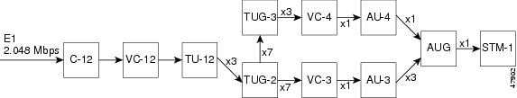
ステップ 5 Administrative Unit Group(AUG; 管理ユニット グループ)のマッピング方法を決定するには、aug mapping {au-3 | au-4} コマンドを使用します(図4-1 を参照)。次に、AUG を AU-3 として設定する例を示します。
Router(config)# controller sonet 1/1/0
Router(config-controller)# aug mapping au-3
AUG を AU-3 に設定すると、次の多重化、アライメント、およびマッピングが設定されます。
C-12 <--> VC-12 <--> TU-12 <--> TUG-2 <--> VC-3 <--> AU-3 <--> AUG
AUG を AU-4 に設定すると、次の多重化、アライメント、およびマッピングが設定されます。
C-12 <--> VC-12 <--> TU-12 <--> TUG-2 <--> TUG-3 <--> VC-4 <--> AU-4 <--> AUG
(注) このコマンドは、SDH フレーミングが設定されている場合に限り有効です。
ステップ 6 すべてのコンフィギュレーション サブコマンドを入力して、設定を完了したら、 Ctrl-Z ( Ctrl キーを押しながら Z キーを押す)を押すか、 end または exit と入力して、コンフィギュレーション モードを終了し、EXEC コマンド インタプリタ プロンプトに戻ります。
ステップ 7 新しい設定を NVRAM に保存します。
Router# copy running-config startup-config
これで基本的な設定の手順は完了です。
PA-MC-STM-1 の AU-3 および TUG-3 の設定
PA-MC-STM-1 の AUG および Tributary Unit Group(TUG; トリビュタリ ユニット グループ)の各ユニットは、TU-12 にマッピングされた E1 リンクのセットを伝播するように設定できます(図4-1 を参照)。
図4-1 PA-MC-STM-1 の多重階層
次の例では、SDH フレーミング、内部クロック ソース、AUG マッピング au-4、およびアイドル パターンを設定しています。
Router(config)# controller sonet 1/1/0
Router(config-controller)# framing sdh
Router(config-controller)# clock source internal
Router(config-controller)# aug mapping au-4
Router(config-controller)# au-4 1 tug-3 2
Router(config-controller-tug3)# mode c-12
Router(config-controller-tug3)# tug-2 4 e1 channel-group 15 timeslots 1-5, 20-23
Router(config-controller-tug3)# idle pattern 0X0
Router(config-controller-tug3)# exit
Router(config-controller)# exit
E1 回線上の論理チャネル グループの設定
E1 回線上に論理チャネル グループを設定するには、 tug-2 tug-2# e1 e1# channel-group channel-group# timeslots list-of-timeslots コマンドを使用します。各パラメータの意味は次のとおりです。
• tug-2# の値は 1 ~ 7 です。
• e1# の値は 1 ~ 3 です。
• channel-group# の値は 0 ~ 30 です。
• list-of-timeslots には、1 ~ 31、またはその中間の範囲の組み合わせ(各範囲は E1 回線を構成するタイム スロットのリスト)を指定できます。
次に、E1 回線上の論理チャネル グループ 15 を設定し、チャネライズド タイム スロット 1 ~ 5 および 20 ~ 23 を、新しく作成する論理チャネル グループに割り当てる例を示します。
Router(config)# controller sonet 1/1/0
Router(config-controller)# framing sdh
Router(config-controller)# aug mapping au-4
Router(config-controller)# au-4 1 tug-3 2
Router(config-controller-tug3)# mode c-12
Router(config-controller-tug3)# tug-2 4 e1 1 channel-group 15 timeslots 1-5, 20-23
Router(config-controller-tug3)# exit
Router(config-controller)# exit
論理チャネル グループ インターフェイスの設定
チャネル グループを作成すれば(E1 回線上の論理チャネル グループの設定を参照)、次のように interface serial コンフィギュレーション コマンドを使用することができます。
Router(config)# controller sonet 1/1/0
Router(config-controller)# framing sdh
Router(config-controller)# aug mapping au-4
Router(config-controller)# au-4 1 tug-3 2
Router(config-controller-tug3)# mode c-12
Router(config-controller-tug3)# tug-2 4 e1 1 channel-group 15 timeslots 1-5, 20-23
Router(config-controller-tug3)# exit
Router(config-controller)# exit
Router(config)# interface serial 1/1/0.1/2/4/1:15
Router(config-if)# ip address 1.1.1.10 255.255.255.252
Router(config-if)# encapsulation ppp
E1 フレームなしチャネルの設定
フレームなしチャネルを作成したり、E1 回線上のチャネルの論理チャネル グループを消去したりするには、次の例のように、tug-2 tug-2# e1 e1# unframed コマンドを使用します。
Router(config)# controller sonet 1/1/0
Router(config-controller)# au-4 1 tug-3 2
Router(config-controller-tug3)# tug-2 4 e1 1 unframed
(注) フレームなし E1 回線のチャネル グループは常に 0 です。
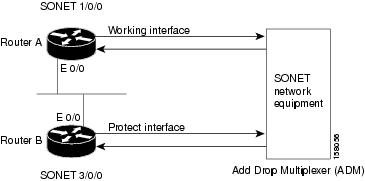
マルチルータ MSP の基本設定
次に、ルータ A およびルータ B に Multiplex Section Protection(MSP)を設定する例を示します(図4-2 を参照)。この例では、ルータ A がワーキング インターフェイス、ルータ B がプロテクト インターフェイスに設定されています。ルータ A 上のワーキング コントローラが使用不能になった場合、自動的にルータ B 上のプロテクト コントローラに接続が切り替えられます。この設定は主に、ラインカードとルータの障害時の対策として使用されます。
図4-2 マルチルータ MSP の基本設定
ルータ A をワーキング コントローラとして設定するには、次のコンフィギュレーションを使用します。
RouterA# configure terminal
RouterA(config)# interface ethernet 0/0
RouterA(config-if)# ip address 7.7.7.7 255.255.255.0
RouterA(config)# controller SONET 1/0/0
RouterA(config-controller)# aps group 1
RouterA(config-controller)# aps working 1
RouterA(config-controller)# end
ルータ B をプロテクト コントローラとして設定するには、次のコンフィギュレーションを使用します。
RouterB# configure terminal
RouterB(config)# interface ethernet 0/0
RouterB(config-if)# ip address 7.7.7.6 255.255.255.0
RouterB(config)# controller SONET 3/0/0
RouterB(config-controller)# aps group 1
RouterB(config-controller)# aps protect 1 7.7.7.7
RouterB(config-controller)# end
ルータ A にシリアル インターフェイスを設定するには、次のコンフィギュレーションを使用します。
RouterA# configure terminal
RouterA(config)# controller SONET 1/0/0
RouterA(config-controller)# au-4 1 tug-3 1
RouterA(config-ctrlr-tug3)# tug-2 1 e1 1 unframed
RouterA(config-controller)# exit
RouterA(config)#interface serial 1/0/0.1/1/1/1:0
RouterA(config-if)# ip address 192.0.1.2 255.255.255.0
ルータ B にシリアル インターフェイスを設定するには、次のコンフィギュレーションを使用します。
RouterB# configure terminal
RouterB(config)# controller SONET 3/0/0
RouterB(config-controller)# au-4 1 tug-3 1
RouterB(config-ctrlr-tug3)# tug-2 1 e1 1 unframed
RouterB(config-controller)# exit
RouterB(config)#interface serial 3/0/0.1/1/1/1:0
RouterB(config-if)# ip address 192.0.1.2 255.255.255.0
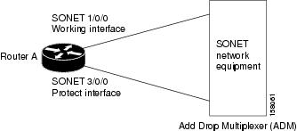
シングルルータ APS の基本設定
次に、ルータ A に Automatic Protection Switching(APS; 自動保護スイッチング)を設定する例を示します(図4-3 を参照)。この例では、ルータ A にワーキング コントローラとプロテクト コントローラの両方を設定します。ワーキング コントローラ SONET 1/0/0 が使用不能になった場合、自動的にプロテクト コントローラSONET 3/0/0 に接続が切り替わります。シングルルータ APS 設定は主に、ラインカード障害時の対策として使用されます。
図4-3 シングルルータ APS の基本設定
ルータ A にループバック インターフェイスを設定するには、次のコンフィギュレーションを使用します。
RouterA# configure terminal
RouterA(config)# interface Loopback 0/0
RouterA(config-if)# ip address 7.7.7.7 255.255.255.255
ワーキング コントローラとプロテクト コントローラを設定するには、次のコンフィギュレーションを使用します。
RouterA# configure terminal
RouterA(config)# controller SONET 1/0/0
RouterA(config-controller)# aps group 1
RouterA(config-controller)# aps working 1
RouterA(config-controller)# exit
RouterA(config)# controller SONET 3/0/0
RouterA(config-controller)# aps group 1
RouterA(config-controller)# aps protect 1 7.7.7.7
RouterA(config-controller)# end
最後にワーキング コントローラとプロテクト コントローラの両方にシリアル インターフェイスを設定するには、次のコンフィギュレーションを使用します。
RouterA(config)# controller SONET 1/0/0
RouterA(config-controller)# au-4 1 tug-3 1
RouterA(config-ctrlr-tug3)# tug-2 1 e1 1 unframed
RouterA(config-controller)# exit
RouterA(config)#interface serial 1/0/0.1/1/1/1:0
RouterA(config-if)# ip address 192.0.1.2 255.255.255.0
RouterA(config)# controller SONET 3/0/0
RouterA(config-controller)# au-4 1 tug-3 1
RouterA(config-ctrlr-tug3)# tug-2 1 e1 1 unframed
RouterA(config-controller)# exit
RouterA(config)#interface serial 3/0/0.1/1/1/1:0
RouterA(config-if)# ip address 192.0.1.2 255.255.255.0
(注) MSP は、SONET コントローラ レベルでのみサポートされます。各 E1 レベルでの保護は、PA-MC-STM1 ではサポートされません。
設定の確認
新規インターフェイスを設定したら、 show コマンドを使用して、新規インターフェイスまたはすべてのインターフェイスのステータスを表示し、 ping コマンドおよび loopback コマンドで接続状態を確認します。ここでは、次の内容について説明します。
• 「show コマンドによる新規インターフェイスのステータス確認」
• 「ping コマンドによるネットワークの接続状態の確認」
• 「loopback コマンドの使用例」
show controllers コマンドの使用例
show controllers コマンドを使用すると、現在のインターフェイス プロセッサとそのインターフェイスがすべて表示されます。
(注) ここに記載されている出力例は、実際のコマンドの出力とは異なる場合があります。これらは、出力の一例です。
show controllers コマンドの出力例を以下に示します。
MEMD at 40000000, 2097152 bytes (unused 3360, recarves 1, lost 0)
RawQ 48000100, ReturnQ 48000108, EventQ 48000110
BufhdrQ 48000128 (2900 items), LovltrQ 48000140 (5 items, 2016 bytes)
IpcbufQ 48000150 (16 items, 4096 bytes)
IpcbufQ_classic 48000148 (8 items, 4096 bytes)
3570 buffer headers (48002000 - 4800FF10)
pool0: 9 buffers, 256 bytes, queue 48000130
pool1: 344 buffers, 1536 bytes, queue 48000138
pool2: 284 buffers, 4544 bytes, queue 48000158
pool3: 4 buffers, 4576 bytes, queue 48000160
slot2: VIP2, hw 2.4, sw 22.20, ccb 5800FF40, cmdq 48000090
software loaded from flash slot0:vip2_22-20.atmdx.191897
IOS (tm) VIP Software (SVIP-DW-M), Experimental Version 11.3
ATM2/0/0, applique is DS3 (45Mbps)
gfreeq 48000158, lfreeq 48000168 (4544 bytes), throttled 0
rxlo 4, rxhi 284, rxcurr 1, maxrxcurr 5
txq 48001A00, txacc 48001A02 (value 284), txlimit 284
show protocols コマンドの使用例
show protocols コマンドを使用すると、システム全体および特定のインターフェイスに設定されているプロトコルが表示されます。
(注) ここに記載されている出力例は、実際のコマンドの出力とは異なる場合があります。これらは、出力の一例です。
show protocols コマンドの出力例を以下に示します。
show running-config コマンドの使用例
show running-config コマンドを使用すると、実行コンフィギュレーション ファイルが表示されます。
(注) ここに記載されている出力例は、実際のコマンドの出力とは異なる場合があります。これらは、出力の一例です。
show running-config コマンドの出力例を以下に示します。
Router# show running-config
Building configuration...
user add admin uid 0 capability admin-access
ip address 10.2.2.8 255.255.255.0
ip broadcast-address 10.2.2.255
ip default-gateway 10.2.2.1
ip route 0.0.0.0 0.0.0.0 10.2.2.1
show startup-config コマンドの使用例
show startup-config コマンドを使用すると、NVRAM に保存されているコンフィギュレーションが表示されます。
(注) ここに記載されている出力例は、実際のコマンドの出力とは異なる場合があります。これらは、出力の一例です。
show startup-config コマンドの出力例を以下に示します。
Router# show startup-config
Building configuration...
service timestamps debug uptime
service timestamps log uptime
no service password-encryption
ip audit po max-events 100
crypto isakmp key cisco123 address 95.95.95.2
crypto ipsec transform-set rtpset esp-des esp-md5-hmac
crypto map rtp 1 ipsec-isakmp
ip address 98.98.98.1 255.255.255.0
ip address 99.99.99.2 255.255.255.0
ip route 0.0.0.0 0.0.0.0 99.99.99.1
access-list 115 permit ip 98.98.98.0 0.0.0.255 10.103.1.0 0.0.0.255
access-list 115 deny ip 98.98.98.0 0.0.0.255 any
FlexWAN モジュールが搭載された Catalyst 6000 ファミリ スイッチおよび Cisco 7600 シリーズ インターネット ルータ-- show version コマンドの出力例
以下に、PA-MC-STM-1 を搭載した Catalyst 6000 ファミリ スイッチで show version コマンドを実行した場合の出力例を示します。
Cisco Internetwork Operating System Software
IOS (tm) MSFC Software (C6MSFC-JSV-M), Version 12.1(20010119:22010]
Copyright (c) 1986-2001 by cisco Systems, Inc.
Compiled Fri 19-Jan-01 14:46 by biff
Image text-base: 0x60008950, data-base: 0x617AC000
ROM: System Bootstrap, Version 12.0(3)XE, RELEASE SOFTWARE
BOOTFLASH: MSFC Software (C6MSFC-BOOT-M), Version 12.0(7)XE1, EARLY DEPLOYMENT )
Switch uptime is 4 hours, 21 minutes
System returned to ROM by reload
System image file is "bootflash:c6msfc-jsv-mz.Feb9"
cisco Cat6k-MSFC (R5000) processor with 114688K/16384K bytes of memory.
Processor board ID SAD03432638
R5000 CPU at 200Mhz, Implementation 35, Rev 2.1, 512KB L2 Cache
X.25 software, Version 3.0.0.
SuperLAT software (copyright 1990 by Meridian Technology Corp).
TN3270 Emulation software.
1 FlexWAN controller (1 Channelized OC3/STM-1).
1 Virtual Ethernet/IEEE 802.3 interface(s)
1 Channelized OC3/STM-1 port(s)
123K bytes of non-volatile configuration memory.
4096K bytes of packet SRAM memory.
16384K bytes of Flash internal SIMM (Sector size 256K).
Configuration register is 0x100Cisco 7200 VXR Routers
Cisco 7200 VXR ルータ-- show version コマンドの出力例
以下に、PA-MC-STM-1 を搭載した Cisco 7200 VXR ルータで show version コマンドを実行した場合の出力例を示します。
Router1-VXR> show version
Cisco Internetwork Operating System Software
IOS (tm) 7200 Software (C7200-P-M), Version 12.1(20010104:023621) ]
Copyright (c) 1986-2001 by cisco Systems, Inc.
Compiled Tue 23-Jan-01 15:34 by biff
Image text-base: 0x60008968, data-base: 0x60C56000
ROM: System Bootstrap, Version 12.0(20000211:194150)
BOOTFLASH: 7200 Software (C7200-BOOT-M), Version 12.0(10)S, EARLY DEPLOYMENT RE)
Router1-VXR uptime is 5 days, 20 hours, 48 minutes
System returned to ROM by reload
System image file is "c7200-p-mz"
cisco 7206VXR (NSE-1) processor (revision A) with 114688K/16384K bytes of memor.
Processor board ID 21288237
R7000 CPU at 262Mhz, Implementation 39, Rev 2.1, 256KB L2, 2000KB L3 Cache
6 slot VXR midplane, Version 2.0
X.25 software, Version 3.0.0.
PXF processor tmc is running.
8 Ethernet/IEEE 802.3 interface(s)
1 FastEthernet/IEEE 802.3 interface(s)
63 Serial network interface(s)
1 Channelized OC3/STM-1 port(s)
125K bytes of non-volatile configuration memory.
20480K bytes of Flash PCMCIA card at slot 0 (Sector size 128K).
4096K bytes of Flash internal SIMM (Sector size 256K).
Configuration register is 0x0
Cisco 7201 ルータ-- show version コマンドの出力例
以下に、Cisco 7201 ルータで実行した show version コマンドの出力例を示します。
Cisco IOS Software, 7200 Software (C7200P-ADVENTERPRISEK9-M), Version 12.4(biffDEV.061001), INTERIM SOFTWARE Copyright (c) 1986-2006 by Cisco Systems, Inc.
Compiled Sun 01-Oct-06 23:42 by biff
ROM: System Bootstrap, Version 12.4(4r)XD5, RELEASE SOFTWARE (fc1)
BOOTLDR: Cisco IOS Software, 7200 Software (C7200P-KBOOT-M), Version 12.4(TAZ3DEV.060927), INTERIM SOFTWARE
c7201alpha1 uptime is 5 days, 18 hours, 32 minutes System returned to ROM by power-on System image file is "disk0:c7200p-adventerprisek9-mz.2006-10-01.biffdev"
This product contains cryptographic features and is subject to United States and local country laws governing import, export, transfer and use. Delivery of Cisco cryptographic products does not imply third-party authority to import, export, distribute or use encryption.
Importers, exporters, distributors and users are responsible for compliance with U.S. and local country laws. By using this product you agree to comply with applicable laws and regulations. If you are unable to comply with U.S. and local laws, return this product immediately.
A summary of U.S. laws governing Cisco cryptographic products may be found at:
http://www.cisco.com/wwl/export/crypto/tool/stqrg.html
If you require further assistance please contact us by sending email to export@cisco.com.
Cisco 7201 (c7201) processor (revision A) with 917504K/65536K bytes of memory.
Processor board ID 2222222222222
MPC7448 CPU at 1666Mhz, Implementation 0, Rev 2.2
1 slot midplane, Version 2.255
4 Gigabit Ethernet interfaces
62443K bytes of USB Flash usbflash0 (Read/Write)
250880K bytes of ATA PCMCIA card at slot 0 (Sector size 512 bytes).
65536K bytes of Flash internal SIMM (Sector size 512K).
Configuration register is 0x2
VIP が搭載された Cisco 7500 シリーズ ルータ-- show version コマンドの出力例
以下に、PA-MC-STM-1 を搭載した Cisco 7500 シリーズ ルータで VIP4-80 から show version コマンドを実行した場合の出力例を示します。
Cisco Internetwork Operating System Software
IOS (tm) RSP Software (RSP-PV-M), Version 12.0(20000912:174226) ]
Copyright (c) 1986-2000 by cisco Systems, Inc.
Compiled Wed 13-Sep-00 04:08 by biff
Image text-base: 0x60010950, data-base: 0x60DA6000
ROM: System Bootstrap, Version 11.1(8)CA1, RELEASE SOFTWARE (fc1)
BOOTFLASH: GS Software (RSP-BOOT-M), Version 11.1(8)CA1, RELEASE SOFTWARE (fc1)
7500_right uptime is 2 minutes
System returned to ROM by reload at 17:20:30 UTC Fri Apr 30 1999
System image file is "tftp://223.255.254.254//tftpboot-users/halrev312sdevtst/rel091300/bin/rsp-pv-mz091300"
cisco RSP4 (R5000) processor with 131072K/2072K bytes of memory.
R5000 CPU at 200Mhz, Implementation 35, Rev 2.1, 512KB L2 Cache
G.703/E1 software, Version 1.0.
G.703/JT2 software, Version 1.0.
X.25 software, Version 3.0.0.
1 EIP controller (6 Ethernet).
1 VIP4-80 RM7000 controller (1 Channelized OC3/STM-1).
6 Ethernet/IEEE 802.3 interface(s)
1 Serial network interface(s)
1 Channelized OC3/STM-1 port(s)
123K bytes of non-volatile configuration memory.
20480K bytes of Flash PCMCIA card at slot 1 (Sector size 128K).
8192K bytes of Flash internal SIMM (Sector size 256K).
No slave installed in slot 7.
Configuration register is 0x0
FlexWAN モジュールが搭載された Catalyst 6000 ファミリ スイッチおよび Cisco 7600 シリーズ インターネット ルータ-- show diag コマンドの出力例
次に示す show diag コマンドの出力例から、FlexWAN モジュールに PA-MC-STM-1 が搭載されていることがわかります。
Board is analyzed ipc ready FlexWAN controller
HW rev 1.3, board revision B0
Serial Number: SAD04340JY3 Part number: 73-3869-07
Slot database information:
Flags: 0x2004 Insertion time: 0x61BFC (04:16:29 ago)
CWAN Controller Memory Size: Unknown
Board is analyzed ipc ready FlexWAN controller
HW rev 1.3, board revision B0
Serial Number: SAD04340JY3 Part number: 73-3869-07
Slot database information:
Flags: 0x2004 Insertion time: 0x622A0 (04:16:27 ago)
Controller Memory Size: 56 MBytes DRAM, 8192 KBytes Packet Memory
IOS (tm) cwlc Software (cwpa-DW-M), Experimental Version 12.1(20010119:v
Channelized OC3/STM-1 SMI PA, 1 port
HW rev 1.00, Board revision UNKNOWN
Serial number: 00000000 Part number: 76-33356-130
Cisco 7200 VXR ルータ-- show diag コマンドの出力例
次の show diag コマンドの出力例では、Cisco 7200 VXR ルータのポート アダプタ スロット 1 に PA-MC-STM-1 が搭載されていることがわかります。
Ethernet Port adapter, 8 ports
Port adapter insertion time 5d20h ago
EEPROM contents at hardware discovery:
Hardware revision 1.14 Board revision A0
Serial number 16733712 Part number 255-65535-255
Test history 0x0 RMA number 255-255-255
0x20: 01 01 01 0E 00 FF 56 10 49 05 6F 08 00 00 00 00
0x30: 50 00 00 00 00 04 29 00 FF FF FF FF FF FF FF FF
(注) Cisco 7200 VXR ルータに搭載したポート アダプタを正常に機能させるには、正しいベース ハードウェア リビジョンが必要です。正しいハードウェア リビジョンが使用されていないと、起動時にエラー メッセージが表示されます。ハードウェアのリビジョンを表示するには、show diag コマンドを使用します。
Cisco 7201 ルータ-- show diag コマンドの出力例
以下に、Cisco 7201 ルータで実行した show version コマンドの出力例を示します。
Dual OC3 POS Port adapter, 2 ports
Port adapter insertion time 00:02:19 ago
EEPROM contents at hardware discovery:
PCB Serial Number : JAE07520DYL
Product (FRU) Number : PA-POS-2OC3
Top Assy. Part Number : 800-21857-02
0x00: 04 FF 40 03 E3 41 01 00 C1 8B 4A 41 45 30 37 35
0x10: 32 30 44 59 4C 82 49 20 1C 02 42 41 30 03 00 81
0x20: 00 00 00 00 04 00 88 00 00 00 00 CB 94 50 41 2D
0x30: 50 4F 53 2D 32 4F 43 33 20 20 20 20 20 20 20 20
0x40: 20 C0 46 03 20 00 55 61 02 FF FF FF FF FF FF FF
0x50: FF FF FF FF FF FF FF FF FF FF FF FF FF FF FF FF
0x60: FF FF FF FF FF FF FF FF FF FF FF FF FF FF FF FF
0x70: FF FF FF FF FF FF FF FF FF FF FF FF FF FF FF FF
VIP が搭載された Cisco 7500 シリーズ ルータ-- show diag コマンドの出力例
次の show diag コマンドの出力例から、インターフェイス プロセッサ スロット 0 に搭載した VIP4-80 のポート アダプタ スロット 2 に PA-MC-STM-1 が搭載されていることがわかります。
Physical slot 2, ~physical slot 0xD, logical slot 2, CBus 0
Master Enable, LED, WCS Loaded
VIP4-80 RM7000 controller, HW rev 2.02, board revision B0
Serial number: 18314858 Part number: 73-3143-02
Test history: 0x00 RMA number: 00-00-00
Flags: cisco 7000 board; 7500 compatible
0x20: 01 22 02 02 01 17 76 6A 49 0C 47 02 00 00 00 00
0x30: 58 00 00 00 00 00 00 00 00 00 00 00 00 00 00 00
Slot database information:
Flags: 0x4 Insertion time: 0x1DB8 (00:02:13 ago)
Controller Memory Size: 64 MBytes DRAM, 65536 KBytes SRAM
Channelized OC3/STM-1 MM PA, 1 port
HW rev 1.00, Board revision 04
Serial number: MIC043626TF Part number: 73-4762-03
FlexWAN モジュールが搭載された Catalyst 6000 ファミリ スイッチおよび Cisco 7600 シリーズ インターネット ルータ-- show interfaces コマンドの出力例
次に示す show interfaces コマンドの出力例から、FlexWAN モジュールに PA-MC-STM-1 が搭載されていることがわかります。
Vlan1 is up, line protocol is up
Hardware is Cat6k RP Virtual Ethernet
MTU 1500 bytes, BW 1000000 Kbit, DLY 10 usec,
reliability 255/255, txload 1/255, rxload 1/255
Encapsulation ARPA, loopback not set
ARP type: ARPA, ARP Timeout 04:00:00
Last input 00:00:00, output never, output hang never
Last clearing of "show interface" counters never
Output queue 0/40, 0 drops; input queue 0/75, 0 drops
5 minute input rate 0 bits/sec, 2 packets/sec
5 minute output rate 0 bits/sec, 0 packets/sec
30459 packets input, 2875285 bytes, 0 no buffer
Received 30419 broadcasts, 0 runts, 0 giants, 0 throttles
0 input errors, 0 CRC, 0 frame, 0 overrun, 0 ignored
343 packets output, 110047 bytes, 0 underruns
0 output errors, 1 interface resets
0 output buffer failures, 0 output buffers swapped out
Cisco 7200 VXR ルータ-- show interfaces コマンドの出力例
次の show interfaces serial コマンドの出力例では、Cisco 7200 VXR ルータのポート アダプタ スロット 1 に搭載された PA-MC-STM-1 上のインターフェイス ポート 0 に関する全情報が示されています。
Router1-VXR> show interfaces serial 1/0.1/1/1/1:0
Serial1/0.1/1/1/1:0 is up, line protocol is up
Hardware is Channelized STM-1 controller
MTU 1500 bytes, BW 1984 Kbit, DLY 20000 usec,
reliability 255/255, txload 1/255, rxload 1/255
Encapsulation HDLC, crc 16, loopback not set
Last input 00:00:01, output 00:00:06, output hang never
Last clearing of "show interface" counters never
Input queue: 0/75/0/0 (size/max/drops/flushes); Total output drops: 0
Queueing strategy: weighted fair
Output queue: 0/1000/64/0 (size/max total/threshold/drops)
Conversations 0/1/16 (active/max active/max total)
Reserved Conversations 0/0 (allocated/max allocated)
5 minute input rate 0 bits/sec, 0 packets/sec
5 minute output rate 0 bits/sec, 0 packets/sec
50594 packets input, 1216008 bytes, 3 no buffer
Received 0 broadcasts, 0 runts, 0 giants, 0 throttles
223 input errors, 24 CRC, 75 frame, 0 overrun, 0 ignored, 124 abort
59092 packets output, 6639740 bytes, 0 underruns
0 output errors, 0 collisions, 0 interface resets
0 output buffer failures, 0 output buffers swapped out
0 carrier transitions no alarm present
Cisco 7201 ルータ-- show interfaces コマンドの出力例
以下に、Cisco 7201 ルータで実行した show interfaces コマンドの出力例を示します。
GigabitEthernet0/0 is up, line protocol is up
Hardware is MV64460 Internal MAC, address is 0019.56c5.2adb (bia
Internet address is 209.165.200.225
MTU 1500 bytes, BW 1000000 Kbit, DLY 10 usec,
reliability 255/255, txload 1/255, rxload 45/255
Encapsulation ARPA, loopback not set
Full-duplex, 1000Mb/s, media type is RJ45
output flow-control is XON, input flow-control is XON
ARP type: ARPA, ARP Timeout 04:00:00
Last input 00:07:03, output 00:00:07, output hang never
Last clearing of "show interface" counters 00:00:04
Input queue: 0/75/0/0 (size/max/drops/flushes); Total output drops: 0
Output queue: 0/40 (size/max)
5 minute input rate 180240000 bits/sec, 430965 packets/sec
5 minute output rate 0 bits/sec, 0 packets/sec
2222975 packets input, 133378500 bytes, 0 no buffer
Received 0 broadcasts, 0 runts, 0 giants, 0 throttles
0 input errors, 0 CRC, 0 frame, 0 overrun, 0 ignored
0 watchdog, 0 multicast, 0 pause input
0 input packets with dribble condition detected
0 packets output, 0 bytes, 0 underruns
0 output errors, 0 collisions, 0 interface resets
0 babbles, 0 late collision, 0 deferred
0 lost carrier, 0 no carrier, 0 pause output
0 output buffer failures, 0 output buffers swapped out
VIP が搭載された Cisco 7500シリーズ ルータ-- show interfaces コマンドの出力例
VIP での show interfaces serial コマンドの出力例を以下に示します。この例では、インターフェイス プロセッサ スロット 2 に搭載した VIP のポート アダプタ スロット 0 に PA-MC-STM-1 が搭載されています。
Router# show interfaces serial 2/0/0.1/1/1/1:1
Serial2/0/0.1/1/1/1:1 is up, line protocol is up
Hardware is cyBus Channelized OC3/STM-1 PA
Internet address is 105.105.105.1/24
MTU 1500 bytes, BW 1984 Kbit, DLY 20000 usec, rely 255/255, load 36/255
Encapsulation HDLC, loopback not set
Last input 00:00:00, output 00:00:00, output hang never
Last clearing of "show interface" counters never
Input queue: 1/75/0 (size/max/drops); Total output drops: 0
Queueing strategy: weighted fair
Output queue: 0/1000/64/0 (size/max total/threshold/drops)
Conversations 0/1/256 (active/max active/max total)
Reserved Conversations 0/0 (allocated/max allocated)
5 minute input rate 286000 bits/sec, 36 packets/sec
5 minute output rate 284000 bits/sec, 36 packets/sec
8019 packets input, 11695347 bytes, 0 no buffer
Received 0 broadcasts, 0 runts, 0 giants, 0 throttles
0 input errors, 0 CRC, 0 frame, 0 overrun, 0 ignored, 0 abort
7991 packets output, 11650799 bytes, 0 underruns
0 output errors, 0 collisions, 0 interface resets
0 output buffer failures, 0 output buffers swapped out
2 carrier transitions no alarm present
Timeslot(s) Used:1-31, Transmitter delay is 0 flags, transmit queue length 6
次の「ping コマンドによるネットワークの接続状態の確認」に進み、PA-MC-STM-1 とスイッチまたはルータのネットワーク接続状態を確認します。
ping コマンドによるネットワークの接続状態の確認
ping コマンドを使用すると、インターフェイス ポートが正常に動作しているかどうかを確認することができます。ここでは、ping コマンドの概要について説明します。コマンドの詳細および例については、「関連資料」に記載されている資料を参照してください。
ping コマンドは、指定した IP アドレスのリモート装置に対して、エコー要求パケットを送信します。エコー要求の送信後、システムは指定された時間だけ、リモート装置からの応答を待機します。各エコー応答は、コンソール端末に感嘆符(!)で表示されます。指定されたタイムアウト時間までに戻されなかった各要求は、ピリオド(.)で表示されます。連続する感嘆符(!!!!!)は正常な接続状態を示します。連続するピリオド(.....)、[timed out] または [failed] メッセージが表示された場合は、接続に障害があることを意味します。
次に、アドレス 10.0.0.10 のリモート サーバに対して ping コマンドを実行し、正常な応答が得られた例を示します。
Router# ping 10.0.0.10 <Return>
Type escape sequence to abort.
Sending 5, 100-byte ICMP Echoes to 10.0.0.10, timeout is 2 seconds:
Success rate is 100 percent (5/5), round-trip min/avg/max = 1/15/64 ms
接続に失敗した場合には、IP アドレスが正しいかどうか、および装置がアクティブ(電源がオンになっている)かどうかを確認し、再度 ping コマンドを実行してください。
次の「loopback コマンドの使用例」に進み、ネットワーク接続状態の確認を終了します。
loopback コマンドの使用例
ループバック テストによって、PA-MC-STM-1 インターフェイスとマルチプレクサ インターフェイスなどのリモート装置との接続をテストすることで、機器の異常を検出し、異常のある機器を分離できます。 loopback サブコマンドを実行すると、インターフェイスはループバック モードになり、 ping コマンドによって生成されたテスト パケットがリモート装置を通じてループできるようになります。パケットがループを完了した場合、接続は正常です。ループを完了しない場合は、ループバック テストのパス内にある装置をエラーの原因として特定できます。
PA-MC-STM-1 は、sonet コントローラ レベルでローカルとネットワークという 2 つのループパック モードをサポートしています。
ループバック モードを設定するには、次のように loopback {local | network} コマンドを使用します。
Router(config)# controller sonet 1/1/0
Router(config-controller)# loopback network
loopback local コマンドを使用すると、ネットワークに送信されたすべてのデータが、受信側へ内部的にループバックされます。このループパック モードでは、シリアル インターフェイスは up/up のループ ステートになります。
loopback network コマンドを使用すると、接続先の装置から受信したすべてのデータが、変更されずに返されます。このループパック モードでは、T1 シリアル インターフェイスは動作しません。
PA-MC-STM-1 では、TUG-3 または AU-3 にマッピングした E1 回線でのループバックもサポートされます。
TUG-3 にマッピングされた E1 回線上のループパックを指定するには、controller tug3 コンフィギュレーション モードで tug-2 e1 loopback コマンドを使用します。
AU-3 にマッピングされた E1 回線上のループパックを指定するには、controller au3 コンフィギュレーション モードで tug-2 e1 loopback コマンドを使用します。
完全な tug-2 e1 loopback コマンド構文は、次のとおりです。
tug-2 tug-2 number e1 e1-number loopback {local | network {line | payload}}
ループパックをディセーブルにするには、このコマンドの no 形式を使用します。
[no] tug-2 tug-2 number e1 e1-number loopback {local | network {line | payload}}
 フィードバック