VRF を使用する GRE トンネルの設定例
概要
このドキュメントでは、Generic Routing Encapsulation(GRE; 総称ルーティング カプセル化)トンネル インターフェイスでの VPN Routing and Forwarding(VRF; VPN ルーティングおよび転送)インスタンスの設定例を紹介しています。
前提条件
要件
この設定を開始する前に、次の要件が満たされていることを確認してください。
このドキュメントの読者は次のトピックについての専門知識を有している必要があります。
使用するコンポーネント
このドキュメントの情報は、3725 シリーズ ルータ上の Cisco IOS® ソフトウェア リリース 12.3(4)T1 に基づくものです。
Cisco Feature Navigator II(登録ユーザ専用)を使用して、GRE トンネル IP 送信元と送信先 VRF メンバーシップ機能を検索し、必要とする追加のソフトウェアおよびハードウェア要件を取得します。
このドキュメントの情報は、特定のラボ環境にあるデバイスに基づいて作成されました。このドキュメントで使用するすべてのデバイスは、初期(デフォルト)設定の状態から起動しています。対象のネットワークが実稼働中である場合には、どのようなコマンドについても、その潜在的な影響について確実に理解しておく必要があります。
表記法
ドキュメント表記の詳細は、「シスコ テクニカル ティップスの表記法」を参照してください。
設定
このセクションでは、このドキュメントで説明する機能を設定するために必要な情報を提供しています。
次の方法で設定を行います。
-
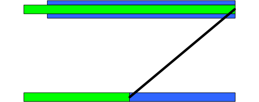
R1-CE と R2-CE は、VRF BLUE にあります。
-
R1-CE は、VRF GREEN にもあり、R3-PE への GRE トンネルを介してアクセスできます。
R1-CE では、スタティック ホスト ルートを使って R3-PE(トンネルの宛先)へアクセスします。このため、(トンネルを介してトンネル宛先アドレスを学習する)GRE トンネルに対する再帰ルーティングは発生しません。
VRF BLUE と VRF GREEN は所有する企業が異なっており、この 2 つの VRF の間でのルートの漏洩は発生しません。または R1-CE と R2-CE 間のインターフェイスに関する Access Control List(ACL; アクセス コントロール リスト)は、R1-CE と R2-CE 間の GRE トラフィックを許可するためだけに使用できます。
注:この文書で使用されているコマンドの詳細を調べるには、「Command Lookup ツール」を使用してください(登録ユーザのみ)。
ネットワーク図
このドキュメントでは、次のネットワーク セットアップを使用します。
図 1 – 物理トポロジ 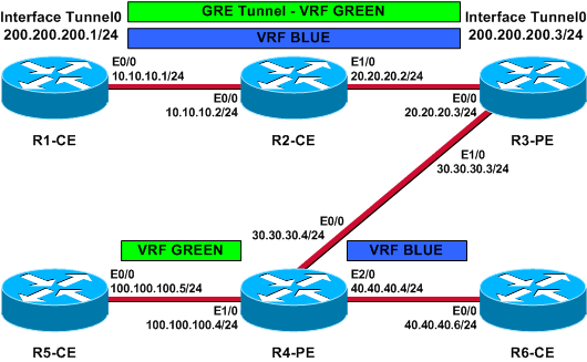
設定
このドキュメントでは、次の構成を使用します。
| R3-PE(トンネル エンドポイント) |
|---|
R3-PE# show running-config Building configuration... . ! no ip domain lookup ! ip vrf blue rd 1:1 route-target export 311:311 route-target import 411:411 ! ip vrf green rd 2:2 route-target export 322:322 route-target import 422:422 ! ip cef ! interface Tunnel0 ip vrf forwarding green ip address 200.200.200.3 255.255.255.0 tunnel source Ethernet0/0 tunnel destination 10.10.10.1 tunnel vrf blue !--- Tunnel 0 is part of VRF GREEN; but it uses the tunnel !--- destination and source addresses from the routing !--- table of VRF BLUE, because of this tunnel vrf blue !--- command. ! interface Ethernet0/0 ip vrf forwarding blue ip address 20.20.20.3 255.255.255.0 !--- Connection to the VRF BLUE network and the VRF GREEN !--- network using the GRE tunnel. ! interface Ethernet1/0 ip address 30.30.30.3 255.255.255.0 tag-switching ip ! router bgp 1 no bgp default ipv4-unicast bgp log-neighbor-changes neighbor 30.30.30.4 remote-as 1 ! address-family vpnv4 neighbor 30.30.30.4 activate neighbor 30.30.30.4 send-community extended exit-address-family ! address-family ipv4 vrf green redistribute connected no auto-summary no synchronization exit-address-family ! address-family ipv4 vrf blue redistribute connected no auto-summary no synchronization exit-address-family ! ip classless ip route vrf blue 10.10.10.1 255.255.255.255 20.20.20.2 !--- Static Host route to ensure that recursive routing !--- does not occur. no ip http server ! . end |
| R4-PE |
|---|
R4-PE# show running-config Building configuration... . . . no ip domain lookup ! ip vrf blue rd 1:1 route-target export 411:411 route-target import 311:311 ! ip vrf green rd 2:2 route-target export 422:422 route-target import 322:322 ! ip cef ! interface Ethernet0/0 ip address 30.30.30.4 255.255.255.0 tag-switching ip ! interface Ethernet1/0 ip vrf forwarding green ip address 100.100.100.4 255.255.255.0 ! interface Ethernet2/0 ip vrf forwarding blue ip address 40.40.40.4 255.255.255.0 ! router bgp 1 no bgp default ipv4-unicast bgp log-neighbor-changes neighbor 30.30.30.3 remote-as 1 ! address-family vpnv4 neighbor 30.30.30.3 activate neighbor 30.30.30.3 send-community extended exit-address-family ! address-family ipv4 vrf green redistribute connected no auto-summary no synchronization exit-address-family ! address-family ipv4 vrf blue redistribute connected no auto-summary no synchronization exit-address-family ! ip classless . . end |
| R1-CE(トンネル エンドポイント) |
|---|
R1-CE# show running-config Building configuration... . . no ip domain lookup ! ip cef ! interface Tunnel0 ip address 200.200.200.1 255.255.255.0 tunnel source Ethernet0/0 tunnel destination 20.20.20.3 !--- Both the tunnel source and destination address are in !--- the VRF BLUE, to provide transport for the VRF GREEN !--- network. ! interface Ethernet0/0 description Connection to R2-CE router ip address 10.10.10.1 255.255.255.0 ip access-group 100 in ip access-group 100 out !--- Access-group to allow only GRE packets through the !--- R2-CE network. However, R1-CE networks data is in the !--- GRE packet. ! ! ip classless ip route 0.0.0.0 0.0.0.0 Tunnel0 ip route 20.20.20.3 255.255.255.255 10.10.10.2 !--- Static Host route to ensure that recursive routing !--- does not occur. no ip http server ! access-list 100 permit gre host 10.10.10.1 host 20.20.20.3 access-list 100 permit gre host 20.20.20.3 host 10.10.10.1 !--- Permits only GRE packets between the endpoints. ! . . end |
| R2-CE |
|---|
R2-CE# show running-config Building configuration... . . no ip domain lookup ! ip cef ! interface Ethernet0/0 description Connection to R1-CE router ip address 10.10.10.2 255.255.255.0 ip access-group 100 in ip access-group 100 out ! interface Ethernet1/0 ip address 20.20.20.2 255.255.255.0 ! ip classless ip route 0.0.0.0 0.0.0.0 20.20.20.3 no ip http server ! access-list 100 permit gre host 10.10.10.1 host 20.20.20.3 access-list 100 permit gre host 20.20.20.3 host 10.10.10.1 !--- Permits only GRE packets between the endpoints. . ! end |
| R5-CE |
|---|
R5-CE# show running-config Building configuration... . . no ip domain lookup ! interface Ethernet0/0 ip address 100.100.100.5 255.255.255.0 ! ! ip classless ip route 0.0.0.0 0.0.0.0 100.100.100.4 no ip http server ! . end |
| R6-CE |
|---|
R6-CE# show running-config Building configuration... . . no ip domain lookup ! interface Ethernet0/0 ip address 40.40.40.6 255.255.255.0 ! ! ip classless ip route 0.0.0.0 0.0.0.0 40.40.40.4 no ip http server ! . end |
確認
ここでは、設定が正しく機能していることを確認するために使用する情報を示します。
一部の show コマンドはアウトプット インタープリタ ツールによってサポートされています(登録ユーザ専用)。このツールを使用することによって、show コマンド出力の分析結果を表示できます。
-
show ip route、show ip route vrf:トンネル宛先が到達可能であることを確認するトンネル エンド ポイントのこれらのコマンドを発行してください。これにより、トンネル インターフェイスがアップ状態になることが確認されます。
-
show ip bgp vpnv4 all labels:PEデバイスでこのコマンドを発行すると、Border Gateway Protocol(BGP)を介して他のPEデバイスに各プレフィクスに配布されたVPNラベルが表示されます。
R3-PE# show ip route vrf blue 10.10.10.1

   Routing entry for 10.10.10.1/32
   Known via "static", distance 1, metric 0
   Routing Descriptor Blocks:
   * 20.20.20.2
   Route metric is 0, traffic share count is 1

R3-PE# show ip route vrf green

Routing Table: green
Codes: C - connected, S - static, R - RIP, M - mobile, B - BGP
       D - EIGRP, EX - EIGRP external, O - OSPF, IA - OSPF inter area
       N1 - OSPF NSSA external type 1, N2 - OSPF NSSA external type 2
       E1 - OSPF external type 1, E2 - OSPF external type 2
       i - IS-IS, su - IS-IS summary, L1 - IS-IS level-1, L2 - IS-IS level-2
       ia - IS-IS inter area, * - candidate default, U - per-user static route
       o - ODR, P - periodic downloaded static route

Gateway of last resort is not set

C    200.200.200.0/24 is directly connected, Tunnel0
     100.0.0.0/24 is subnetted, 1 subnets
B       100.100.100.0 [200/0] via 30.30.30.4, 01:11:45

R3-PE# show interfaces tunnel 0

   Tunnel0 is up, line protocol is up
   Hardware is Tunnel
   Internet address is 200.200.200.3/24
   MTU 1514 bytes, BW 9 Kbit, DLY 500000 usec,
   reliability 255/255, txload 1/255, rxload 1/255
   Encapsulation TUNNEL, loopback not set
   Keepalive not set
   Tunnel source 20.20.20.3 (Ethernet0/0), destination 10.10.10.1
   Tunnel protocol/transport GRE/IP, key disabled, sequencing disabled
   Tunnel TTL 255
   Checksumming of packets disabled, fast tunneling enabled
   Last input 00:44:05, output 00:26:16, output hang never
   Last clearing of "show interface" counters never
   Input queue: 0/75/0/0 (size/max/drops/flushes); Total output drops: 0
   Queueing strategy: fifo
   Output queue: 0/0 (size/max)
   5 minute input rate 0 bits/sec, 0 packets/sec
   5 minute output rate 0 bits/sec, 0 packets/sec
   105 packets input, 11964 bytes, 0 no buffer
   Received 0 broadcasts, 0 runts, 0 giants, 0 throttles
   0 input errors, 0 CRC, 0 frame, 0 overrun, 0 ignored, 0 abort
   83 packets output, 10292 bytes, 0 underruns
   0 output errors, 0 collisions, 0 interface resets
   0 output buffer failures, 0 output buffers swapped out

R3-PE# show ip bgp vpnv4 all labels

      Network          Next Hop      In label/Out label
Route Distinguisher: 1:1 (blue)
   20.20.20.0/24    0.0.0.0         16/aggregate(blue)
Route Distinguisher: 2:2 (green)
   100.100.100.0/24 30.30.30.4      nolabel/16
   200.200.200.0    0.0.0.0         17/aggregate(green)

R4-PE# show ip route vrf blue

Routing Table: blue
Codes: C - connected, S - static, R - RIP, M - mobile, B - BGP
       D - EIGRP, EX - EIGRP external, O - OSPF, IA - OSPF inter area
       N1 - OSPF NSSA external type 1, N2 - OSPF NSSA external type 2
       E1 - OSPF external type 1, E2 - OSPF external type 2
       i - IS-IS, su - IS-IS summary, L1 - IS-IS level-1, L2 - IS-IS level-2
       ia - IS-IS inter area, * - candidate default, U - per-user static route
       o - ODR, P - periodic downloaded static route

Gateway of last resort is not set

     20.0.0.0/24 is subnetted, 1 subnets
B       20.20.20.0 [200/0] via 30.30.30.3, 01:14:05

R4-PE# show ip route vrf green

Routing Table: green
Codes: C - connected, S - static, R - RIP, M - mobile, B - BGP
       D - EIGRP, EX - EIGRP external, O - OSPF, IA - OSPF inter area
       N1 - OSPF NSSA external type 1, N2 - OSPF NSSA external type 2
       E1 - OSPF external type 1, E2 - OSPF external type 2
       i - IS-IS, su - IS-IS summary, L1 - IS-IS level-1, L2 - IS-IS level-2
       ia - IS-IS inter area, * - candidate default, U - per-user static route
       o - ODR, P - periodic downloaded static route

Gateway of last resort is not set

B    200.200.200.0/24 [200/0] via 30.30.30.3, 01:14:10
     100.0.0.0/24 is subnetted, 1 subnets
C       100.100.100.0 is directly connected, Ethernet1/0

R1-CE# show ip route 20.20.20.3

   Routing entry for 20.20.20.3/32
   Known via "static", distance 1, metric 0
   Routing Descriptor Blocks:
   * 10.10.10.2
   Route metric is 0, traffic share count is 1

R1-CE# show interfaces tunnel 0

   Tunnel0 is up, line protocol is up
   Hardware is Tunnel
   Internet address is 200.200.200.1/24
   MTU 1514 bytes, BW 9 Kbit, DLY 500000 usec,
   reliability 255/255, txload 1/255, rxload 1/255
   Encapsulation TUNNEL, loopback not set
   Keepalive not set
   Tunnel source 10.10.10.1 (Ethernet0/0), destination 20.20.20.3
   Tunnel protocol/transport GRE/IP, key disabled, sequencing disabled
   Tunnel TTL 255
   Checksumming of packets disabled, fast tunneling enabled
   Last input 00:26:57, output 00:26:57, output hang never
   Last clearing of "show interface" counters never
   Input queue: 0/75/0/0 (size/max/drops/flushes); Total output drops: 0
   Queueing strategy: fifo
   Output queue: 0/0 (size/max)
   5 minute input rate 0 bits/sec, 0 packets/sec
   5 minute output rate 0 bits/sec, 0 packets/sec
   83 packets input, 10292 bytes, 0 no buffer
   Received 0 broadcasts, 0 runts, 0 giants, 0 throttles
   0 input errors, 0 CRC, 0 frame, 0 overrun, 0 ignored, 0 abort
   106 packets output, 12088 bytes, 0 underruns
   0 output errors, 0 collisions, 0 interface resets
   0 output buffer failures, 0 output buffers swapped out

R5-CE# ping 200.200.200.1

Type escape sequence to abort.
Sending 5, 100-byte ICMP Echos to 200.200.200.1, timeout is 2 seconds:
!!!!!
Success rate is 100 percent (5/5), round-trip min/avg/max = 40/54/80 ms

R5-CE# ping 200.200.200.3

Type escape sequence to abort.
Sending 5, 100-byte ICMP Echos to 200.200.200.3, timeout is 2 seconds:
!!!!!
Success rate is 100 percent (5/5), round-trip min/avg/max = 20/36/72 ms
トラブルシュート
現在、この設定に関する特定のトラブルシューティング情報はありません。
警告
本機能の設定に関して、これまでに下記の警告項目が特定されています。Bug Toolkit(登録ユーザ専用)を使って、不具合を検索できます。
-
CSCea81266(登録ユーザ専用):解決済み(R) GRE:clear ip route * 実行後、GRE トラフィックのフローが停止します。
-
CSCdx74855(登録ユーザ専用):解決済み(R):ローカルGREトンネルインターフェイスのIPアドレスにpingを実行できない。
-
CSCdx57718(登録ユーザ専用):Resolved (R) IP packet loss in GRE tunnel when Cisco Express Forwarding (CEF) disabled on outgoing interface.
 フィードバック