TE トンネルを介した MPLS VPN の実装
内容
概要
このドキュメントでは、MPLS ネットワークでトラフィック エンジニアリング(TE)トンネルを使用したマルチプロトコル ラベル スイッチング(MPLS)VPN を実装する場合の設定例について説明します。TE トンネルを使用した MPLS VPN の利点を活用するには、これらの両方がネットワーク上で共存している必要があります。このドキュメントでは、さまざまなシナリオを使用して、TE トンネルを介した MPLS VPN でパケット転送が失敗する理由について説明します。また、考えられるソリューションについても説明します。
前提条件
要件
このドキュメントの読者は次のトピックについての専門知識を有している必要があります。
使用するコンポーネント
このドキュメントの内容は、特定のソフトウェアやハードウェアのバージョンに限定されるものではありません。
表記法
ドキュメント表記の詳細は、『シスコ テクニカル ティップスの表記法』を参照してください。
背景理論
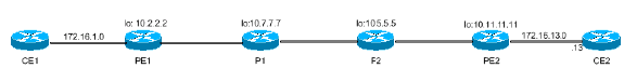
このトポロジに示すように、シンプルな MPLS VPN の設定では、プロバイダー エッジ 1(PE1)は、PE2 から直接、マルチプロトコル ボーダー ゲートウェイ プロトコル(MPBGP)を介して VPN プレフィックス 172.16.13.0/24 の VPN のラベル(ラベル 1 [L1])を学習します。この場合、ネクスト ホップは PE2 ループバック アドレスになります。また、PE1 は、Label Distribution Protocol(LDP)を経由して、PE2 のループバック アドレス用のラベル(L2)をネクスト ホップ P1 から学習します。
データを VPN プレフィックス 172.16.13.13 に転送する場合、PE1 はラベル スタック {L2 L1} を使用して、L2 を外部ラベルとします。L2はトランジットラベルスイッチルータ(LSR)P1によってスワップされます。P2は外部L2をポップし、1つのL1だけでパケットをPE2に転送します。P2がL2をポップする理由については、RFC 3031のセクション3.1. ![]() これにより、VPN IP バージョン 4(IPv4)プレフィックス 172.16.13.0/24 へのパケットは、MPLS ネットワークを使用してラベル スイッチングされます。
これにより、VPN IP バージョン 4(IPv4)プレフィックス 172.16.13.0/24 へのパケットは、MPLS ネットワークを使用してラベル スイッチングされます。
MPLS VPN の転送動作は、いずれかの P ルータが、({L2 L1} ラベル スタックではなく)唯一の外部ラベルとして L1(VPN ラベル)の付いたパケットを受信すると失敗します。これは、どの P ルータにも、ラベル転送情報ベース(LFIB)にパケットをスイッチするための L1 がないために発生します。
MPLS TE では、ラベルを交換する場合に Resource Reservation Protocol(RSVP)が使用されます。ルータが TE および Tag Distribution Protocol(TDP)/LDP の両方を使用できるよう設定されている場合、ルータは、特定のプレフィックスに対する LDP と RSVP の両方から異なるラベルを受信します。LDP および RSVP からのラベルは、必ずしも同じである必要はありません。ルータは、プレフィックスを LDP インターフェイス経由で学習する場合、LDP ラベルを転送テーブルにインストールします。プレフィックスを TE トンネル インターフェイス経由で学習する場合は、RSVP ラベルを転送テーブルにインストールします。
通常の TE トンネル(トンネルで LDP/TDP が有効になっていない)の場合、入力 LSR(TE トンネルのヘッドエンドにある LSR)では、TE トンネルを経由して学習するすべてのルートの TE トンネルのテールエンドに到達するために使用されるラベルと同じラベルが使用されます。
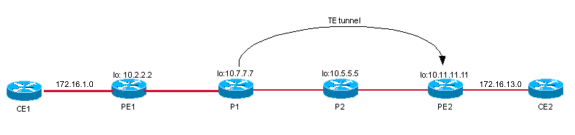
たとえば、トンネルを経由してプレフィックス 10.11.11.11/32 を学習する、PE1 から P2 への TE トンネルがあるとします。P2のトンネルテールエンドは10.5.5.5で、PE1の10.5.5.5に到達するラベルはL3です。PE1はL3を使用して宛先10.11.11.11/32に到達し、TEトンネルを介して学習します。
上記のシナリオでは、PE1 と P2 の間に TE トンネルがある場合は、PE1 はデータをカスタマー エッジ 2(CE2)に転送しています。 L4 が VPN ラベルの場合、PE1 は、ラベル スタック {L3 L4} を使用してデータを転送します。P1はL3をポップし、P2はL4のパケットを受信します。PE2は外部ラベルL4のパケットを正しく転送できる唯一のLSRです。P2はPE2とのMPBGPセッションを持っていないため、L2の情報はをドロップします。
設定および show の出力は、前述の状況およびこの問題を解決するためのソリューションの 1 つを示します。
CE1 と CE2 の間の VPN 初期設定(TE トンネル不使用)
トポロジ
コンフィギュレーション
ここには、コンフィギュレーション ファイルの中で関連のある部分だけが示されています。
| PE1 |
|---|
hostname PE1 ip cef ! ip vrf aqua rd 100:1 route-target export 1:1 route-target import 1:1 ! mpls traffic-eng tunnels ! interface Loopback0 ip address 10.2.2.2 255.255.255.255 no ip directed-broadcast ! interface Ethernet2/0/1 ip vrf forwarding aqua ip address 172.16.1.2 255.255.255.0 ! interface Ethernet2/0/2 ip address 10.7.7.2 255.255.255.0 ip router isis mpls traffic-eng tunnels tag-switching ip ! router isis passive-interface Loopback0 net 47.1234.2222.2222.2222.00 is-type level-1 metric-style wide mpls traffic-eng router-id Loopback0 mpls traffic-eng level-1 ! router bgp 1 bgp log-neighbor-changes neighbor 10.11.11.11 remote-as 1 neighbor 10.11.11.11 update-source Loopback0 ! address-family vpnv4 neighbor 10.11.11.11 activate neighbor 10.11.11.11 send-community extended exit-address-family ! address-family ipv4 neighbor 10.11.11.11 activate no auto-summary no synchronization exit-address-family ! address-family ipv4 vrf aqua redistribute connected no auto-summary no synchronization exit-address-family |
| PE2 |
|---|
hostname PE2 ! ip vrf aqua rd 100:1 route-target export 1:1 route-target import 1:1 ! mpls traffic-eng tunnels ! interface Loopback0 ip address 10.11.11.11 255.255.255.255 ! interface POS0/1 ip address 10.12.12.10 255.255.255.0 ip router isis mpls traffic-eng tunnels tag-switching ip crc 16 clock source internal ! interface POS5/1 ip vrf forwarding aqua ip address 172.16.13.11 255.255.255.0 crc 32 clock source internal ! router isis passive-interface Loopback0 mpls traffic-eng router-id Loopback0 mpls traffic-eng level-1 net 47.1234.1010.1010.1010.00 is-type level-1 metric-style wide ! router bgp 1 bgp log-neighbor-changes neighbor 10.2.2.2 remote-as 1 neighbor 10.2.2.2 update-source Loopback0 no auto-summary ! address-family vpnv4 neighbor 10.2.2.2 activate neighbor 10.2.2.2 send-community extended exit-address-family ! address-family ipv4 vrf aqua redistribute connected no auto-summary no synchronization exit-address-family ! |
確認
PE2は、PE1とPE2の間のMPBGPピアリングを介してPE1 VPN IPv4プレフィックス172.16.1.0/24を学習します。次に示します。
PE2# show ip route vrf aqua
Codes: C - connected, S - static, I - IGRP, R - RIP, M - mobile, B - BGP
       D - EIGRP, EX - EIGRP external, O - OSPF, IA - OSPF inter area
       N1 - OSPF NSSA external type 1, N2 - OSPF NSSA external type 2
       E1 - OSPF external type 1, E2 - OSPF external type 2, E - EGP
       i - IS-IS, L1 - IS-IS level-1, L2 - IS-IS level-2, ia - IS-IS inter area
       * - candidate default, U - per-user static route, o - ODR

Gateway of last resort is not set

     10.0.0.0/24 is subnetted, 2 subnets
B       172.16.1.0 [200/0] via 10.2.2.2, 16:09:10
C       172.16.13.0 is directly connected, POS5/1
同様に、PE1はPE1とPE2の間のMPBGPピアリングを介してPE2 VPN IPv4プレフィックス172.16.13.0/24を学習します。次に示します。
PE1# show ip route vrf aqua
Codes: C - connected, S - static, I - IGRP, R - RIP, M - mobile, B - BGP
       D - EIGRP, EX - EIGRP external, O - OSPF, IA - OSPF inter area
       N1 - OSPF NSSA external type 1, N2 - OSPF NSSA external type 2
       E1 - OSPF external type 1, E2 - OSPF external type 2, E - EGP
       i - IS-IS, L1 - IS-IS level-1, L2 - IS-IS level-2, ia - IS-IS inter area
       * - candidate default, U - per-user static route, o - ODR

Gateway of last resort is not set

     10.0.0.0/24 is subnetted, 2 subnets
B       172.16.13.0 [200/0] via 10.11.11.11, 16:09:49
C       172.16.1.0 is directly connected, Ethernet2/0/1

PE1# show ip route vrf aqua 172.16.13.13
Routing entry for 172.16.13.0/24
  Known via "bgp 1", distance 200, metric 0, type internal
  Last update from 10.11.11.11 16:13:19 ago
  Routing Descriptor Blocks:
  * 10.11.11.11 (Default-IP-Routing-Table), from 10.11.11.11, 16:13:19 ago
      Route metric is 0, traffic share count is 1
      AS Hops 0, BGP network version 0

PE1# show ip cef vrf aqua 172.16.13.13
172.16.13.0/24, version 11, cached adjacency 10.7.7.7
0 packets, 0 bytes
  tag information set
    local tag: VPN route head
    fast tag rewrite with Et2/0/2, 10.7.7.7, tags imposed {17 12308}
  via 10.11.11.11, 0 dependencies, recursive
    next hop 10.7.7.7, Ethernet2/0/2 via 10.11.11.11/32
    valid cached adjacency
    tag rewrite with Et2/0/2, 10.7.7.7, tags imposed {17 12308}

!--- The label stack used to reach 172.16.13.13 is !--- {17 12308}, where 17 is the outer label to reach next hop 10.11.11.11 !--- and 12308 is the VPN IPv4 label for 172.16.13.0/24.


PE1# show ip cef 10.11.11.11
10.11.11.11/32, version 31, cached adjacency 10.7.7.7
0 packets, 0 bytes
  tag information set
    local tag: 21
    fast tag rewrite with Et2/0/2, 10.7.7.7, tags imposed {17}
  via 10.7.7.7, Ethernet2/0/2, 1 dependency
    next hop 10.7.7.7, Ethernet2/0/2
    valid cached adjacency
    tag rewrite with Et2/0/2, 10.7.7.7, tags imposed {17}

!--- Outer label 17 is used to reach next hop 10.11.11.11.
したがって、CE1 は、ラベル スタック {17 12308} を使用して PE1 上に設定されている VPN ルーティング/転送(VRF)インスタンス「aqua」を経由して、CE2 ネットワーク上の 172.16.13.13 に到達できます。
この ping の出力により、接続性を確認できます。
CE1# ping 172.16.13.13

Type escape sequence to abort.
Sending 5, 100-byte ICMP Echos to 172.16.13.13, timeout is 2 seconds:
!!!!!
Success rate is 100 percent (5/5), round-trip min/avg/max = 1/1/4 ms
ケース 1:TE トンネルを使用した VPN(TE トンネルが PE1 から PE2 の場合)
トポロジ
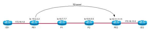
自動ルート通知を使用して TE トンネルが PE ルータ間に構築されている場合、出力 PE の BGP ネクスト ホップは、TE トンネル インターフェイスを経由して到達します。このため、PE1 は、TE ラベルを使用して PE2 に到達します。
注:MPLS TEはLDPから独立しています。つまり、PEからPEへのフルメッシュのトンネルがある場合は、ルータでLDPを有効に無効にでき、TEトンネルインターフェイスでLDPを実行する必要はありません。ただし、VPN バージョン 4(VPNv4)ルートの BGP ネクスト ホップに対し、すべてのトンネルを確立する必要があります。この設定の例では、このBGPネクストホップがPE2のLoopback0であることがわかります。このループバックは、PE1からPE2へのトンネルの宛先でもあります。この例では、リターントラフィック用にPE2からPE1へのトンネルがあるは..次に、TE トンネルを介してすべての VPNv4 トラフィックが伝送され、CE 間での転送が行われます。BGP ネクスト ホップが TE トンネル宛先と同一でない場合は、LDP をコアと TE トンネルで実行する必要があります。
コンフィギュレーション
PE トンネルを確立するための PE1 への追加設定を、次に示します。
| PE1 |
|---|
PE1# show run interface tunnel 0 ! interface Tunnel0 ip unnumbered Loopback0 no ip directed-broadcast no ip route-cache distributed tunnel destination 10.11.11.11 tunnel mode mpls traffic-eng tunnel mpls traffic-eng autoroute announce tunnel mpls traffic-eng path-option 10 dynamic end |
確認
PE1# show ip cef vrf aqua 172.16.13.13
172.16.13.0/24, version 11
0 packets, 0 bytes
  tag information set
    local tag: VPN route head
    fast tag rewrite with Tu0, point2point, tags imposed {19 12308}
  via 10.11.11.11, 0 dependencies, recursive
    next hop 10.11.11.11, Tunnel0 via 10.11.11.11/32
    valid adjacency
    tag rewrite with Tu0, point2point, tags imposed {19 12308}

!--- The label stack to reach 172.16.13.13 is {19 12308}. !--- BGP next hop for the VPNv4 prefix is 10.11.11.11, which is !--- the same as the TE tunnel destination.


PE1# show ip route  10.11.11.11
Routing entry for 10.11.11.11/32
  Known via "isis", distance 115, metric 40, type level-1
  Redistributing via isis
  Last update from 10.11.11.11 on Tunnel0, 00:02:09 ago
  Routing Descriptor Blocks:
  * 10.11.11.11, from 10.11.11.11, via Tunnel0

!--- The route is via Tunnel0.

      Route metric is 40, traffic share count is 1
次に、Tunnel0 を経由してネクストホップ 10.11.11.11 に到達するために使用する外部ラベルを確認します。
PE1# show mpls traffic-eng tunnels tunnel 0

Name: PE1_t0                              (Tunnel0) Destination: 10.11.11.11
  Status:
    Admin: up         Oper: up     Path: valid       Signalling: connected

    path option 10, type dynamic (Basis for Setup, path weight 30)

  Config Parameters:
    Bandwidth: 0        kbps (Global)  Priority: 7  7   Affinity: 0x0/0xFFFF
    Metric Type: TE (default)
    AutoRoute:  enabled   LockDown: disabled  Loadshare: 0        bw-based
    auto-bw: disabled

  InLabel  :  -
  OutLabel : Ethernet2/0/2, 19

!--- Label 19 from RSVP is used to reach destination 10.11.11.11/32.

  RSVP Signalling Info:
       Src 10.2.2.2, Dst 10.11.11.11, Tun_Id 0, Tun_Instance 31
    RSVP Path Info:
      My Address: 10.7.7.2
      Explicit Route: 10.7.7.7 10.8.8.7 10.8.8.5 10.12.12.10
                      10.11.11.11
      Record   Route:  NONE
      Tspec: ave rate=0 kbits, burst=1000 bytes, peak rate=0 kbits
    RSVP Resv Info:
      Record   Route:  NONE
      Fspec: ave rate=0 kbits, burst=1000 bytes, peak rate=Inf
  Shortest Unconstrained Path Info:
    Path Weight: 30 (TE)
    Explicit Route: 10.7.7.2 10.7.7.7 10.8.8.7 10.8.8.5
                    10.12.12.10 10.11.11.11
  History:
    Tunnel:
      Time since created: 17 hours, 17 minutes
      Time since path change: 32 minutes, 54 seconds
    Current LSP:
      Uptime: 32 minutes, 54 seconds
    Prior LSP:
      ID: path option 10 [14]
      Removal Trigger: tunnel shutdown
この情報を表示する別の方法として、次に示す show コマンドの出力修飾子を使用する方法があります。
PE1# show mpls traffic-eng tunnels tunnel 0 | include Label
  InLabel  :  -
  OutLabel : Ethernet2/0/2, 19

!--- This is the label to reach 10.11.11.11.
次のタグ スタックを確認してください。TE ラベル 19 が、Tunnel0 を使用してネクストホップ 10.11.11.0 にパケットを転送するために使用されています。
PE1# show tag forwarding-table 10.11.11.11 detail
Local  Outgoing    Prefix            Bytes tag  Outgoing   Next Hop
tag    tag or VC   or Tunnel Id      switched   interface
21     Pop tag     10.11.11.11/32    0          Tu0        point2point
        MAC/Encaps=14/18, MTU=1500, Tag Stack{19}, via Et2/0/2
        00603E2B02410060835887428847 00013000
        No output feature configured
    Per-packet load-sharing, slots: 0 1 2 3 4 5 6 7 8 9 10 11 12 13 14 15
PE1#
これにより、PE1 は、ラベル スタック {19 12308} を使用して、172.16.13.13 宛てのパケットを送信します。P1はラベル19をスワップします。パケットはP2に到達し、その外部ラベルがポップされます。次に、ラベル 12308 だけを使用してパケットが PE2 に転送されます。
PE2 では、ラベル 12308 のパケットが受信され、転送テーブルの情報に基づいてこのバケットがスイッチされます。これは、以下に示されています。
PE2# show tag for tags 12308 detail
Local  Outgoing    Prefix            Bytes tag  Outgoing   Next Hop
tag    tag or VC   or Tunnel Id      switched   interface
12308  Aggregate   172.16.13.0/24[V]  12256
        MAC/Encaps=0/0, MTU=0, Tag Stack{}
        VPN route: aqua
        No output feature configured
    Per-packet load-sharing, slots: 0 1 2 3 4 5 6 7 8 9 10 11 12 13 14 15
PE2#
注:発信タグが集約であるため、発信インターフェイスは表示されません。これは、ラベルに関連付けられているプレフィックスが直接接続ルートとなっていることが原因です。
CE1 から CE2 のホストに PING を行うと、TE トンネルを経由した VPN の接続性を確認できます。
CE1# ping  172.16.13.13

Type escape sequence to abort.
Sending 5, 100-byte ICMP Echos to 172.16.13.13, timeout is 2 seconds:
!!!!!
Success rate is 100 percent (5/5), round-trip min/avg/max = 4/13/36 ms
CE1#
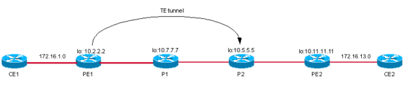
ケース 2:TE トンネルを使用した VPN(TE トンネルが PE1 から P2 の場合)
トポロジ
コンフィギュレーション
PE1 の基本設定を使用した TE への追加設定は、次のとおりです。
| PE1 |
|---|
PE1# show run interface tunnel 0 ! interface Tunnel0 ip unnumbered Loopback0 no ip directed-broadcast no ip route-cache distributed tunnel destination 10.5.5.5 tunnel mode mpls traffic-eng tunnel mpls traffic-eng autoroute announce tunnel mpls traffic-eng path-option 10 dynamic end ! |
確認
PE1 VRF aqua のプレフィックス 172.16.13.13 へのルートをチェックします。このルートは、ラベル スタック {19 12308} を使用したネクストホップ 10.11.11.11/32(Tunnel0 経由)を指します。
PE1# show ip cef vrf aqua 172.16.13.13
172.16.13.0/24, version 11
0 packets, 0 bytes
  tag information set
    local tag: VPN route head
    fast tag rewrite with Tu0, point2point, tags imposed {19 12308}
  via 10.11.11.11, 0 dependencies, recursive
    next hop 10.5.5.5, Tunnel0 via 10.11.11.11/32
    valid adjacency
    tag rewrite with Tu0, point2point, tags imposed {19 12308}
PE1#
次に示すように、外部ラベルであるラベル 19 を使用して、ネクストホップ 10.11.11.11/32 に到達します。
PE1# show ip cef 10.11.11.11
10.11.11.11/32, version 37
0 packets, 0 bytes
  tag information set
    local tag: 21
    fast tag rewrite with Tu0, point2point, tags imposed {19}
  via 10.5.5.5, Tunnel0, 1 dependency
    next hop 10.5.5.5, Tunnel0
    valid adjacency
    tag rewrite with Tu0, point2point, tags imposed {19}

PE1# show mpls traffic-eng tunnels tunnel 0

Name: PE1_t0                              (Tunnel0) Destination: 10.5.5.5
  Status:
    Admin: up         Oper: up     Path: valid       Signalling: connected

    path option 10, type dynamic (Basis for Setup, path weight 20)

  Config Parameters:
    Bandwidth: 0        kbps (Global)  Priority: 7  7   Affinity: 0x0/0xFFFF
    Metric Type: TE (default)
    AutoRoute:  enabled   LockDown: disabled  Loadshare: 0        bw-based
    auto-bw: disabled

  InLabel  :  -
  OutLabel : Ethernet2/0/2, 19
  RSVP Signalling Info:
       Src 10.2.2.2, Dst 10.5.5.5, Tun_Id 0, Tun_Instance 33
    RSVP Path Info:
      My Address: 10.7.7.2
      Explicit Route: 10.7.7.7 10.8.8.7 10.8.8.5 10.5.5.5
      Record   Route:  NONE
      Tspec: ave rate=0 kbits, burst=1000 bytes, peak rate=0 kbits
    RSVP Resv Info:
      Record   Route:  NONE
      Fspec: ave rate=0 kbits, burst=1000 bytes, peak rate=Inf
  Shortest Unconstrained Path Info:
    Path Weight: 20 (TE)
    Explicit Route: 10.7.7.2 10.7.7.7 10.8.8.7 10.8.8.5
                    10.5.5.5
  History:
    Tunnel:
      Time since created: 17 hours, 31 minutes
      Time since path change: 8 minutes, 49 seconds
    Current LSP:
      Uptime: 8 minutes, 49 seconds
      Selection: reoptimation
    Prior LSP:
      ID: path option 10 [31]
      Removal Trigger: path verification failed
PE1#

PE1# show mpls traffic-eng tunnels tunnel 0 | i Label
  InLabel  :  -
  OutLabel : Ethernet2/0/2, 19
PE1#
PE1 からのパケットは、ラベル スタック {19 12308} を使用して、TE トンネル経由で送信されます。P1 はパケットを受信すると、タグ 19 をポップ(PHP)し、ラベル スタック {12308} を使用してこのパケットを送信します。show コマンドを使用すると、このことを確認できます。
P1> show tag for tag 19
Local  Outgoing    Prefix            Bytes tag  Outgoing   Next Hop
tag    tag or VC   or Tunnel Id      switched   interface
19     Pop tag     10.2.2.2 0 [33]   2130       Et2/0      10.8.8.5
P1>

P1> show tag for tag 19 detail
Local  Outgoing    Prefix            Bytes tag  Outgoing   Next Hop
tag    tag or VC   or Tunnel Id      switched   interface
19     Pop tag     10.2.2.2 0 [33]   2257       Et2/0      10.8.8.5
        MAC/Encaps=14/14, MTU=1504, Tag Stack{}
        006009E08B0300603E2B02408847
        No output feature configured
P1>
P2 は、ラベル スタック {12308} のパケットを受信すると LFIB をチェックしますが、LFIB との一致が存在しないため、このパケットをドロップします。P2 での show コマンド出力は、次のとおりです。
P2# show tag forwarding-table tags 12308 detail
Local  Outgoing    Prefix            Bytes tag  Outgoing   Next Hop
tag    tag or VC   or Tunnel Id      switched   interface
P2#

P2#
7w4d: TAG: Et0/3: recvd: CoS=0, TTL=253, Tag(s)=12308
7w4d: TAG: Et0/3: recvd: CoS=0, TTL=253, Tag(s)=12308
7w4d: TAG: Et0/3: recvd: CoS=0, TTL=253, Tag(s)=12308
7w4d: TAG: Et0/3: recvd: CoS=0, TTL=253, Tag(s)=12308
P2#
P2#
説明
この問題を解決するには、TE トンネルの TDP/LDP を有効にして、この TDP/LDP をタグ スイッチング インターフェイスにします。解決策に示されている例では、TDPはPE1のTunnel0で有効になっています。P2は、ディレクテッドhelloを受け入れ、ディレクテッドTDPネイバーを形成するように設定されています。これにより、PE1 は、LDP を経由して、P2 から 10.11.11.11 のラベルを受信します。Tunnel0 がタグ スイッチング インターフェイスになり、TDP が 10.11.11.11 へのトラフィックに対して有効になったため、PE1 では、両方のラベルが使用されます。RSVP ラベルは TE テールエンドに到達するために使用され、TDP ラベルは 10.11.11.11 に到達するために使用されます。
このシナリオでは、以下に該当する場合、PE1 はラベル スタック {L2 L3 L1} を使用してデータを CE2 に転送します。
-
L1 は VPN ラベルです。
-
L2 は TE テールエンドに到達するために使用される RSVP ラベルです。
-
L3 は 10.11.11.11(P2 から受信)に到達するために使用される TDP ラベルです。
解決方法
ソリューションとして、TE トンネル上で TDP を有効にします。
コンフィギュレーション
以下に、TDP が有効になっている PE1 での TE トンネル設定を示します。追加部分は、太字で示されています。
| PE1 |
|---|
PE1# show run interface tunnel 0 ! interface Tunnel0 ip unnumbered Loopback0 no ip directed-broadcast no ip route-cache distributed tag-switching ip !--- This enables TDP. tunnel destination 10.5.5.5 tunnel mode mpls traffic-eng tunnel mpls traffic-eng autoroute announce tunnel mpls traffic-eng path-option 10 dynamic end ! |
以下に、指定された TDP hello を受け入れるための、TE トンネルのテールエンドでの追加設定を示します。
P2# show run | i directed-hello
tag-switching tdp discovery directed-hello accept

!--- This configures P2 to accept directed TDP hellos.

P2#
確認
PE1# show tag tdp neighbor | i Peer
    Peer TDP Ident: 10.7.7.7:0; Local TDP Ident 10.2.2.2:0
    Peer TDP Ident: 10.5.5.5:0; Local TDP Ident 10.2.2.2:0

PE1#
PE1# show ip cef vrf aqua 172.16.13.13
172.16.13.0/24, version 11
0 packets, 0 bytes
  tag information set
    local tag: VPN route head
    fast tag rewrite with Tu0, point2point, tags imposed {19 18 12308}
  via 10.11.11.11, 0 dependencies, recursive
    next hop 10.5.5.5, Tunnel0 via 10.11.11.11/32
    valid adjacency
    tag rewrite with Tu0, point2point, tags imposed {19 18 12308}
PE1#

PE1# show mpls traffic-eng tunnels tunnel 0 | i Label
  InLabel  :  -
  OutLabel : Ethernet2/0/2, 19

!--- This is the TE label learned via RSVP.

PE1#
PE1# show tag tdp bind 10.11.11.11 32
  tib entry: 10.11.11.11/32, rev 20
        local binding:  tag: 21
        remote binding: tsr: 10.7.7.7:0, tag: 17
        remote binding: tsr: 10.5.5.5:0, tag: 18

!--- This is the TDP label from P2.
P1は、ラベルスタック{19 18 12308}のパケットを受信すると、タグ19をポップし、ラベルスタック{18 12308}のパケットをP2に送信します。P2はラベル18のLFIBを確認し、発信インターフェイスPO2/0/0 PE1に送信しますPE1はラベル12308のパケットを受信し、CE2に正常に切り替えます。
P2# show tag for tag 18
Local  Outgoing    Prefix            Bytes tag  Outgoing   Next Hop
tag    tag or VC   or Tunnel Id      switched   interface
18     Pop tag     10.11.11.11/32    117496     POS2/0/0    point2point

P2# show tag tdp discovery
 Local TDP Identifier:
    10.5.5.5:0
    Discovery Sources:
    Interfaces:
        Ethernet0/3 (tdp): xmit/recv
            TDP Id: 10.7.7.7:0
        POS2/0/0 (tdp): xmit/recv
            TDP Id: 10.11.11.11:0
    Directed Hellos:
        10.5.5.5 -> 10.2.2.2 (tdp): passive, xmit/recv
            TDP Id: 10.2.2.2:0

P2# show tag tdp neighbor 10.2.2.2
    Peer TDP Ident: 10.2.2.2:0; Local TDP Ident 10.5.5.5:0
        TCP connection: 10.2.2.2.711 - 10.5.5.5.11690
        State: Oper; PIEs sent/rcvd: 469/465; Downstream
        Up time: 01:41:08
        TDP discovery sources:
          Directed Hello 10.5.5.5 -> 10.2.2.2, passive
        Addresses bound to peer TDP Ident:
          10.7.7.2        172.16.47.166   10.2.2.2

PE1# show tag tdp neighbor 10.5.5.5
    Peer TDP Ident: 10.5.5.5:0; Local TDP Ident 10.2.2.2:0
        TCP connection: 10.5.5.5.11690 - 10.2.2.2.711
        State: Oper; PIEs sent/rcvd: 438/441; Downstream
        Up time: 01:35:08
        TDP discovery sources:
          Directed Hello 10.2.2.2 -> 10.5.5.5, active

!--- This indicates the directed neighbor.

          Addresses bound to peer TDP Ident:
          10.5.5.5        10.12.12.5      10.8.8.5

PE1# show ip route 10.11.11.11
Routing entry for 10.11.11.11/32
  Known via "isis", distance 115, metric 40, type level-1
  Redistributing via isis
B  Last update from 10.5.5.5 on Tunnel0, 01:52:21 ago
  Routing Descriptor Blocks:
  * 10.5.5.5, from 10.11.11.11, via Tunnel0
      Route metric is 40, traffic share count is 1
CE1 から CE2 のホストに ping コマンドを発行することで、このソリューションの有効性を確認します。
CE1# ping 172.16.13.13

Type escape sequence to abort.
Sending 5, 100-byte ICMP Echos to 172.16.13.13, timeout is 2 seconds:
!!!!!
Success rate is 100 percent (5/5), round-trip min/avg/max = 4/4/4 ms
CE1#
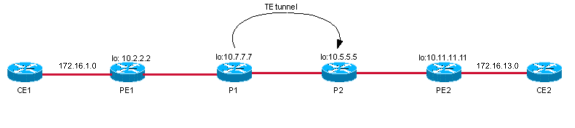
ケース 3:P1 から P2 への TE トンネルを使用した CE1 と CE2 の間の VPN(TDP/LDP が有効化されていない場合)
トポロジ
コンフィギュレーション
PE1 のトンネル設定を次に示します。
| PE1 |
|---|
P1# show run interface tunnel 0 Building configuration... Current configuration : 255 bytes ! interface Tunnel0 ip unnumbered Loopback0 no ip directed-broadcast ip route-cache distributed tunnel destination 10.5.5.5 tunnel mode mpls traffic-eng tunnel mpls traffic-eng autoroute announce tunnel mpls traffic-eng path-option 10 dynamic end |
確認
CE2 172.16.13.13 宛てのパケットがどのようにスイッチされるかを確認します。show ip cef コマンド出力は、172.16.13.13 宛てのパケットがラベル スタック {17 12308} を使用してスイッチされることを示します。
PE1# show ip cef vrf aqua 172.16.13.13
172.16.13.0/24, version 18, cached adjacency 10.7.7.7
0 packets, 0 bytes
  tag information set
    local tag: VPN route head
    fast tag rewrite with Et2/0/2, 10.7.7.7, tags imposed {17 12308}
  via 10.11.11.11, 0 dependencies, recursive
    next hop 10.7.7.7, Ethernet2/0/2 via 10.11.11.11/32
    valid cached adjacency
    tag rewrite with Et2/0/2, 10.7.7.7, tags imposed {17 12308}
P1はこのパケットを受信すると、外部ラベル17を削除し、Tunnel0へのIPルーティングテーブルを調べた後にパケットを切り替えます。この出力のimplicit-null OutLabelに注目してください。これは、発信インターフェイスはラベル スイッチングされていないことを意味します。
P1# show ip cef 10.11.11.11 detail
10.11.11.11/32, version 52
0 packets, 0 bytes
  tag information set
    local tag: 17
    fast tag rewrite with Tu0, point2point, tags imposed {}
  via 10.5.5.5, Tunnel0, 0 dependencies
    next hop 10.5.5.5, Tunnel0
    valid adjacency
    tag rewrite with Tu0, point2point, tags imposed {}

P1# show mpls traffic-eng tunnel tunnel 0 | i Label
  InLabel  :  -
  OutLabel : Ethernet2/0, implicit-null
P1# show tag for 10.11.11.11 detail
Local  Outgoing    Prefix            Bytes tag  Outgoing   Next Hop
tag    tag or VC   or Tunnel Id      switched   interface
17     Untagged    10.11.11.11/32    882        Tu0        point2point
        MAC/Encaps=14/14, MTU=1500, Tag Stack{}, via Et2/0
        006009E08B0300603E2B02408847
        No output feature configured
    Per-packet load-sharing, slots: 0 1 2 3 4 5 6 7 8 9 10 11 12 13 14 15
P1# show ip route 10.11.11.11
Routing entry for 10.11.11.11/32
  Known via "isis", distance 115, metric 30, type level-1
  Redistributing via isis
  Last update from 10.5.5.5 on Tunnel0, 00:03:20 ago
  Routing Descriptor Blocks:
  * 10.5.5.5, from 10.11.11.11, via Tunnel0
      Route metric is 30, traffic share count is 1
P2 は、ラベル 12308 のパケットを受信すると、転送テーブルを調べます。P2 は CE2 からの VPN タグ 12308 を認識できないため、パケットをドロップします。
P2# show tag for tag 12308 detail
Local  Outgoing    Prefix            Bytes tag  Outgoing   Next Hop
tag    tag or VC   or Tunnel Id      switched   interface
これにより、CE2を宛先とするVPNパケットのパスが切断されます。これは、CE2 172.16.13.13/32へのpingによって確認されます。
PE1#
CE1# ping 172.16.13.13

Type escape sequence to abort.
Sending 5, 100-byte ICMP Echos to 172.16.13.13, timeout is 2 seconds:
.....
Success rate is 0 percent (0/5)
CE1#
解決方法
ソリューションとして、トンネルを使用する LDP/TDP を有効にします。次のセクションでは、このソリューションについて説明します。
ケース 4:P1 と P2 の間の TE トンネルを使用した VPN(LDP が有効化されている場合)
トポロジ
コンフィギュレーション
トンネルで LDP が有効になっていると、P1 での設定は次のようになります。追加部分は、太字で示されています。
| PE1 |
|---|
P1# show run interface tunnel 0 Building configuration... Current configuration : 273 bytes ! interface Tunnel0 ip unnumbered Loopback0 no ip directed-broadcast ip route-cache distributed mpls label protocol ldp tunnel destination 10.5.5.5 tunnel mode mpls traffic-eng tunnel mpls traffic-eng autoroute announce tunnel mpls traffic-eng path-option 10 dynamic end ! |
確認
PE1 は、ラベル スタック {17 12308} を使用して、プレフィックス 172.16.13.13/32 にパケットを送信します。
PE1#
PE1# show tag for 10.11.11.11 detail
Local  Outgoing    Prefix            Bytes tag  Outgoing   Next Hop
tag    tag or VC   or Tunnel Id      switched   interface
21     17          10.11.11.11/32    0          Et2/0/2    10.7.7.7
        MAC/Encaps=14/18, MTU=1500, Tag Stack{17}
        00603E2B02410060835887428847 00011000
        No output feature configured
    Per-packet load-sharing, slots: 0 1 2 3 4 5 6 7 8 9 10 11 12 13 14 15

PE1#
PE1# show ip cef 10.11.11.11 detail
10.11.11.11/32, version 60, cached adjacency 10.7.7.7
0 packets, 0 bytes
  tag information set
    local tag: 21
    fast tag rewrite with Et2/0/2, 10.7.7.7, tags imposed {17}
  via 10.7.7.7, Ethernet2/0/2, 1 dependency
    next hop 10.7.7.7, Ethernet2/0/2
    valid cached adjacency
    tag rewrite with Et2/0/2, 10.7.7.7, tags imposed {17}

PE1# show ip cef vrf aqua 172.16.13.13
172.16.13.0/24, version 18, cached adjacency 10.7.7.7
0 packets, 0 bytes
  tag information set
    local tag: VPN route head
    fast tag rewrite with Et2/0/2, 10.7.7.7, tags imposed {17 12308}
  via 10.11.11.11, 0 dependencies, recursive
    next hop 10.7.7.7, Ethernet2/0/2 via 10.11.11.11/32
    valid cached adjacency
    tag rewrite with Et2/0/2, 10.7.7.7, tags imposed {17 12308}
P1 は、ラベル スタック {17 12308} のパケットを受信し、ラベル 17 の LFIB を探します。
P1# show tag for tag 17 detail
Local  Outgoing    Prefix            Bytes tag  Outgoing   Next Hop
tag    tag or VC   or Tunnel Id      switched   interface
17     18          10.11.11.11/32    1158       Tu0        point2point
        MAC/Encaps=14/18, MTU=1496, Tag Stack{18}, via Et2/0
        006009E08B0300603E2B02408847 00012000
        No output feature configured
    Per-packet load-sharing, slots: 0 1 2 3 4 5 6 7 8 9 10 11 12 13 14 15
P1#

P1# show ip cef 10.11.11.11 detail
10.11.11.11/32, version 52
0 packets, 0 bytes
  tag information set
    local tag: 17
    fast tag rewrite with Tu0, point2point, tags imposed {18}
  via 10.5.5.5, Tunnel0, 0 dependencies
    next hop 10.5.5.5, Tunnel0
    valid adjacency
    tag rewrite with Tu0, point2point, tags imposed {18}
ラベル17をラベル18にスワップする必要があることを示しています。したがって、そのパケットはラベルスタック{18 12308}を使用してトンネルインターフェイスでスイッチングされます。
P2 は、トンネル インターフェイスを使用して、ラベル スタック {18 12308} のパケットを受信します。P2 は、タグ 18 をポップして(最後から 2 番目のホップ ルータであるため)、ラベル 12308 のパケットを PE2 へスイッチします。
P2# show tag for tag 18 detail
Local  Outgoing    Prefix            Bytes tag  Outgoing   Next Hop
tag    tag or VC   or Tunnel Id      switched   interface
18     Pop tag     10.11.11.11/32    127645     PO2/0/0    point2point
        MAC/Encaps=4/4, MTU=4474, Tag Stack{}
        0F008847
        No output feature configured
    Per-packet load-sharing, slots: 0 1 2 3 4 5 6 7 8 9 10 11 12 13 14 15
P2#
PE2 は、ラベル 12308 のパケットを受信して、このパケットを CE2 へ正常にスイッチします。
PE2# show tag forwarding tags 12308 detail
Local  Outgoing    Prefix            Bytes tag  Outgoing   Next Hop
tag    tag or VC   or Tunnel Id      switched   interface
12308  Aggregate   172.16.13.0/24[V]  12256
        MAC/Encaps=0/0, MTU=0, Tag Stack{}
        VPN route: aqua
        No output feature configured
    Per-packet load-sharing, slots: 0 1 2 3 4 5 6 7 8 9 10 11 12 13 14 15
PE2#

CE1# ping 172.16.13.13

Type escape sequence to abort.
Sending 5, 100-byte ICMP Echos to 172.16.13.13, timeout is 2 seconds:
!!!!!
Success rate is 100 percent (5/5), round-trip min/avg/max = 1/2/4 ms
CE1#
Case 6:P1 と PE2 の間のトンネルを使用した MPLS VPN
トポロジ
コンフィギュレーション
| PE1 |
|---|
P1# show run interface tunnel 0 Building configuration... Current configuration : 258 bytes ! interface Tunnel0 ip unnumbered Loopback0 no ip directed-broadcast ip route-cache distributed tunnel destination 10.11.11.11 tunnel mode mpls traffic-eng tunnel mpls traffic-eng autoroute announce tunnel mpls traffic-eng path-option 10 dynamic end |
確認
PE1 は、ラベル スタック {17 12308} を使用して、172.16.13.13 宛てのパケットをネクストホップ 10.11.11.11 に送信します。
PE1# show ip cef vrf aqua 172.16.13.13
172.16.13.0/24, version 18, cached adjacency 10.7.7.7
0 packets, 0 bytes
  tag information set
    local tag: VPN route head
    fast tag rewrite with Et2/0/2, 10.7.7.7, tags imposed {17 12308}
  via 10.11.11.11, 0 dependencies, recursive
    next hop 10.7.7.7, Ethernet2/0/2 via 10.11.11.11/32
    valid cached adjacency
    tag rewrite with Et2/0/2, 10.7.7.7, tags imposed {17 12308}
P1 は、ラベル スタック {17 12308} のパケットを受信します。P1 は、LFIB テーブルを調べてタグ スタック {17} をチェックし、ラベル {17} のパケットを P2 へとスイッチします。
P1# show tag for 10.11.11.11 detail
Local  Outgoing    Prefix            Bytes tag  Outgoing   Next Hop
tag    tag or VC   or Tunnel Id      switched   interface
17     Untagged    10.11.11.11/32    411        Tu0        point2point
        MAC/Encaps=14/18, MTU=1500, Tag Stack{17}, via Et2/0
        006009E08B0300603E2B02408847 00011000
        No output feature configured
    Per-packet load-sharing, slots: 0 1 2 3 4 5 6 7 8 9 10 11 12 13 14 15

P1# show tag for tag 17 detail
Local  Outgoing    Prefix            Bytes tag  Outgoing   Next Hop
tag    tag or VC   or Tunnel Id      switched   interface
17     Untagged    10.11.11.11/32    685        Tu0        point2point
        MAC/Encaps=14/18, MTU=1500, Tag Stack{17}, via Et2/0
        006009E08B0300603E2B02408847 00011000
        No output feature configured
    Per-packet load-sharing, slots: 0 1 2 3 4 5 6 7 8 9 10 11 12 13 14 15
P1#

P1# show ip cef 10.11.11.11
10.11.11.11/32, version 67
0 packets, 0 bytes
  tag information set
    local tag: 17
    fast tag rewrite with Tu0, point2point, tags imposed {17}
  via 10.11.11.11, Tunnel0, 0 dependencies
    next hop 10.11.11.11, Tunnel0
    valid adjacency
    tag rewrite with Tu0, point2point, tags imposed {17}
P2 は、ラベル スタック {17 12308} のパケットを受信します。最後から 2 番目のホップ ルータである P2 は、ラベル 17 をポップします。
P2# show tag for tag 17 detail
Local  Outgoing    Prefix            Bytes tag  Outgoing   Next Hop
tag    tag or VC   or Tunnel Id      switched   interface
17     Pop tag     10.7.7.7 0 [5]    535        PO2/0/0    point2point
        MAC/Encaps=4/4, MTU=4474, Tag Stack{}
        0F008847
        No output feature configured
P2#
次に、PE2はラベル12308のパケットを受信します。P2は、ラベル12308の宛先が直接接続されていることを認識します。したがって、CE1 から CE2 に ping を発行すると、10 が出力されます。
PE2# show tag for tag 12308 detail
Local  Outgoing    Prefix            Bytes tag  Outgoing   Next Hop
tag    tag or VC   or Tunnel Id      switched   interface
12308  Aggregate   172.16.13.0/24[V]  12776
        MAC/Encaps=0/0, MTU=0, Tag Stack{}
        VPN route: aqua
        No output feature configured
    Per-packet load-sharing, slots: 0 1 2 3 4 5 6 7 8 9 10 11 12 13 14 15
PE2#
注:発信タグが集約であるため、発信インターフェイスは表示されません。これは、ラベルに関連付けられているプレフィックスが直接接続ルートとなっていることが原因です。
CE1# ping 172.16.13.13

Type escape sequence to abort.
Sending 5, 100-byte ICMP Echos to 172.16.13.13, timeout is 2 seconds:
!!!!!
Success rate is 100 percent (5/5), round-trip min/avg/max = 4/4/4 ms
CE1#
既知の問題
詳細については、Field Notice:Cisco IOS® ソフトウェアでの TE を介した MPLS VPN と MPLS InterAS の注意を参照してください。
結論
TE トンネルが出力 PE で終端されている場合は、追加設定をしなくても、MPLS VPN と TE は連携して動作します。TE トンネルがいずれかの P ルータ(コアの PE の前)で終端されている場合は、外部ラベルとして VPN ラベルを使用してパケットが到達しますが、これらのデバイスの LFIB にこの外部ラベルがないため、MPLS VPN トラフィック転送は失敗します。このため、これらの中間ルータは、最終宛先である VPN カスタマー ネットワークにパケットを転送できません。この問題を解決するには、TE トンネルで LDP/TDP を有効にする必要があります。
関連情報
更新履歴
| 改定 | 発行日 | コメント |
|---|---|---|
1.0 |
10-Aug-2005
|
初版 |
 フィードバック