アタッチビットセットの設定
ダウンロード オプション
偏向のない言語
この製品のドキュメントセットは、偏向のない言語を使用するように配慮されています。このドキュメントセットでの偏向のない言語とは、年齢、障害、性別、人種的アイデンティティ、民族的アイデンティティ、性的指向、社会経済的地位、およびインターセクショナリティに基づく差別を意味しない言語として定義されています。製品ソフトウェアのユーザインターフェイスにハードコードされている言語、RFP のドキュメントに基づいて使用されている言語、または参照されているサードパーティ製品で使用されている言語によりドキュメントに例外が存在する場合があります。シスコのインクルーシブ ランゲージの取り組みの詳細は、こちらをご覧ください。
翻訳について
シスコは世界中のユーザにそれぞれの言語でサポート コンテンツを提供するために、機械と人による翻訳を組み合わせて、本ドキュメントを翻訳しています。ただし、最高度の機械翻訳であっても、専門家による翻訳のような正確性は確保されません。シスコは、これら翻訳の正確性について法的責任を負いません。原典である英語版(リンクからアクセス可能)もあわせて参照することを推奨します。
概要
このドキュメントでは、Intermediate System(IS)からIntermediate System(IS)へのアタッチビットの動作について説明します。
前提条件
要件
次の項目に関する知識があることが推奨されます。
- ISIS
- Open Shortest Path First(OSPF)
使用するコンポーネント
このドキュメントの内容は、特定のソフトウェアやハードウェアのバージョンに限定されるものではありません。
このドキュメントの情報は、特定のラボ環境にあるデバイスに基づいて作成されました。このドキュメントで使用するすべてのデバイスは、初期(デフォルト)設定の状態から起動しています。対象のネットワークが実稼働中である場合には、どのようなコマンドについても、その潜在的な影響について確実に理解しておく必要があります。
背景説明
ISISに関する注意点とアタッチビットの動作を次に示します。
1. ISISネットワークには、レベル1(L1)ルータ、レベル2(L2)ルータ、およびレベル1レベル2(L1L2)ルータの3つのタイプがあります。
2. OSPFと同様に、ISISにはバックボーンエリアとしてL2エリアがあります。
3.レベル1とレベル2の両方のエリアに接続されているルータをL1L2ルートと呼びます。
4. OSPFには、Shortest Path First(SPF)の計算範囲を制限する複数のエリアの概念があり、ISISに異なるエリアを持つ理由も同じです。
5.レベル1およびレベル2 ISISルータは、それぞれレベル1およびレベル2リンクステートPDU(LSP)を生成します。L1L2ルータは両方のLSP(レベル1とレベル2)を生成します。
6.場合は、レベル1ルータがL2ネットワークに到達する必要があり、レベル1ルータはバックボーンエリアに到達するためにパケットをL1L2ルータに送信します。
7.デフォルトでは、レベル2ルータはL1L2ルータによってレベル1エリアにリークされませんが、レベル1ルータは常にレベル2エリアに伝搬されます。
8.レベル2エリアに到達するために、L1L2ルータはレベル1 LSPにアタッチビットを設定します。レベル1ルータはルーティングテーブルにデフォルトルートを設定します。このルートはL1L2ルータを指します。
9.ネットワークに同じL1エリアに接続する複数のL1L2ルータがある場合、レベル2ルートがレベル1エリアに流れないため、最適でないルーティングが発生する可能性があります。レベル1エリアは、最も近いL1L2ルータをポイントするデフォルトルートのみをインストールします。レベル2ルートをレベル1にリークすることで、これらの制限を克服できます。
設定
ネットワーク図
ループ防止技法を理解するために、このネットワーク トポロジを検討します。
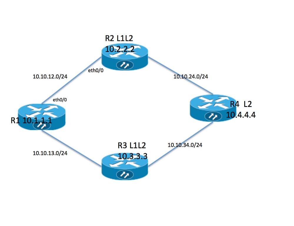
トポロジ情報
- R1はエリア49.0001のLevel1ルータです
- R2とR3は49.0001のL1L2ルータです
- R4はエリア49.0002のレベル2ルータです
- R1にはループバックアドレス10.1.1.1があります
- R2ループバックアドレスは10.2.2.2
- R3アドレスは10.3.3.3です。
- R4ループバックアドレスは10.4.4.4です
R1
R1#sh run int lo 0
Building configuration...

Current configuration : 82 bytes
!
interface Loopback0
 ip address 10.1.1.1 255.255.255.255
 ip router isis 1
end


R1#sh run int ethernet 0/0
Building configuration...

Current configuration : 127 bytes
!
interface Ethernet0/0
 ip address 10.10.12.1 255.255.255.0
 ip router isis 1
 isis circuit-type level-1
end

R1#sh run int ethernet 0/1
Building configuration...

Current configuration : 111 bytes
!
interface Ethernet0/1
 ip address 10.10.13.1 255.255.255.0
 ip router isis 1
 isis circuit-type level-1
end
!

router isis 1
 net 49.0001.0000.0000.0001.00  >>>>> Area is 49.0001
 is-type level-1    >>>>>>>>>> Globally this router belongs to Level1
R2
R2#sh run int lo 0
Building configuration...

Current configuration : 82 bytes
!
interface Loopback0
 ip address 10.2.2.2 255.255.255.255
 ip router isis 1
end

R2#sh run int eth0/0
Building configuration...

Current configuration : 111 bytes
!
interface Ethernet0/0
 ip address 10.10.12.2 255.255.255.0
 ip router isis 1
 isis circuit-type level-1   >>>>>> Circuit type is L1 towards R1
end

R2#sh run int eth0/1
Building configuration...

Current configuration : 84 bytes
!
interface Ethernet0/1
 ip address 10.10.24.2 255.255.255.0
 ip router isis 1
end
!

router isis 1
 net 49.0001.0000.0000.0002.00
R3
R3#sh run int lo 0
Building configuration...

Current configuration : 82 bytes
!
interface Loopback0
 ip address 10.3.3.3 255.255.255.255
 ip router isis 1
end

R3#sh run int eth0/0
Building configuration...

Current configuration : 84 bytes
!
interface Ethernet0/0
 ip address 10.10.13.3 255.255.255.0
 ip router isis 1
end

R3#sh run int eth0/1
Building configuration...

Current configuration : 84 bytes
!
interface Ethernet0/1
 ip address 10.10.34.3 255.255.255.0
 ip router isis 1
end
!

router isis 1
 net 49.0001.0000.0000.0003.00
R4
R4#sh run int lo 0
Building configuration...

Current configuration : 82 bytes
!
interface Loopback0
 ip address 10.4.4.4 255.255.255.255
 ip router isis 1
end

R4#sh run int ethernet 0/0
Building configuration...

Current configuration : 84 bytes
!
interface Ethernet0/0
 ip address 10.10.24.4 255.255.255.0
 ip router isis 1
end

R4#sh run int ethernet 0/1
Building configuration...

Current configuration : 84 bytes
!
interface Ethernet0/1
 ip address 10.10.34.4 255.255.255.0
 ip router isis 1
end

!

router isis 1
 net 49.0002.0000.0000.0004.00   >>>> Area on R4 is 49.0002.
注:2つの異なるエリア間のルータは、常にレベル2ネイバー関係から来ています。この例では、R4エリアは49.0002で、R2エリアとR3エリアは49.0001です。したがって、R4はR2とR3とのL2隣接関係を持つ必要があります。
確認
ここでは、設定が正常に機能しているかどうかを確認します。
R1#show clns neighbors
Tag 1:
System Id      Interface   SNPA                State  Holdtime  Type Protocol
R2             Et0/0       aabb.cc01.f600      Up     6         L1   IS-IS
R3             Et0/1       aabb.cc01.f700      Up     9         L1   IS-IS
R1#

R1 neighbor relationship with R2 and R3 is only L1
R2#sh clns neighbors
Tag 1:
System Id      Interface   SNPA                State  Holdtime  Type Protocol
R1             Et0/0       aabb.cc01.f500      Up     24        L1   IS-IS
R4             Et0/1       aabb.cc01.f800      Up     9         L2   IS-IS

R2 neighbor relationship with R1 is L1
R2 neighbor relationship with R4 is L2

So R2 is L1L2 router as it is building both adjanceny i.e. L1 and L2 neighbor
R3#sh clns neighbors
Tag 1:
System Id      Interface   SNPA                State  Holdtime  Type Protocol
R1             Et0/0       aabb.cc01.f510      Up     25        L1   IS-IS
R4             Et0/1       aabb.cc01.f810      Up     7         L2   IS-IS

R3 neighbor relatioship with R1 is L1
R3 neighbor relationship with R4 is L2

So R3 is L1L2 router as it is building both adjanceny i.e. L1 and L2 neighbor
R4#sh clns neighbors
Tag 1:
System Id      Interface   SNPA                State  Holdtime  Type Protocol
R2             Et0/0       aabb.cc01.f610      Up     29        L2   IS-IS
R3             Et0/1       aabb.cc01.f710      Up     23        L2   IS-IS

R4 neighbor relationship with R2 and R3 is L2 only .
このトポロジでは、R2とR3はL1L2ルータであるため、R1はアタッチビットを設定する必要があり、その結果、R1には2つのデフォルトルートが必要になります。
R1#show isis database

Tag 1:
IS-IS Level-1 Link State Database:
LSPID                 LSP Seq Num  LSP Checksum  LSP Holdtime      ATT/P/OL
R1.00-00            * 0x0000002B   0x4269        576               0/0/0
R2.00-00              0x00000033   0xB1CA        997               1/0/0
R2.01-00              0x0000001F   0x42F0        1018              0/0/0
R3.00-00              0x0000002B   0xCA5E        857               1/0/0
R3.01-00              0x0000001B   0x50E4        964               0/0/0

ATT ( which is marked in Bold ) represents attach bit and is set to 1 for both R2 and R3
router in Level 1 LSP . ATT bit is only set in Level1 LSP .
R1#sh ip route
Codes: L - local, C - connected, S - static, R - RIP, M - mobile, B - BGP
       D - EIGRP, EX - EIGRP external, O - OSPF, IA - OSPF inter area
       N1 - OSPF NSSA external type 1, N2 - OSPF NSSA external type 2
       E1 - OSPF external type 1, E2 - OSPF external type 2
       i - IS-IS, su - IS-IS summary, L1 - IS-IS level-1, L2 - IS-IS level-2
       ia - IS-IS inter area, * - candidate default, U - per-user static route
       o - ODR, P - periodic downloaded static route, H - NHRP, l - LISP
       a - application route
       + - replicated route, % - next hop override

Gateway of last resort is 10.10.13.3 to network 0.0.0.0

i*L1  0.0.0.0/0 [115/10] via 10.10.13.3, 00:00:26, Ethernet0/1
                [115/10] via 10.10.12.2, 00:00:26, Ethernet0/0
      10.0.0.0/8 is variably subnetted, 9 subnets, 2 masks
C        10.1.1.1/32 is directly connected, Loopback0
i L1     10.2.2.2/32 [115/20] via 10.10.12.2, 00:00:26, Ethernet0/0
i L1     10.3.3.3/32 [115/20] via 10.10.13.3, 00:46:55, Ethernet0/1
C        10.10.12.0/24 is directly connected, Ethernet0/0
L        10.10.12.1/32 is directly connected, Ethernet0/0
C        10.10.13.0/24 is directly connected, Ethernet0/1
L        10.10.13.1/32 is directly connected, Ethernet0/1
i L1     10.10.24.0/24 [115/20] via 10.10.12.2, 00:00:26, Ethernet0/0
i L1     10.10.34.0/24 [115/20] via 10.10.13.3, 00:46:55, Ethernet0/1


In route table R1 is installing default route towards R2 and R3 .
デフォルトではレベル2ルートはレベル1エリアにリークされないため、ここで示すルーティングテーブルにはR4の特定のルートはありません。トラフィックの転送はデフォルトテーブルに依存し、これにより最適でないルーティングが発生する可能性があります。上記の場合、両方が同じメトリックであるため、両方のデフォルトルートがインストールされました。R1とR2の間でメトリックが増加した場合、ルータはR2へのデフォルトルートだけをインストールする必要があります。
R1(config)#int eth0/0
R1(config-if)#isis metric 20 >>>>> Metric is increased by 20

R1#sh ip route 0.0.0.0
Routing entry for 0.0.0.0/0, supernet
  Known via "isis", distance 115, metric 10, candidate default path, type level-1
  Redistributing via isis 1
  Last update from 10.10.13.3 on Ethernet0/1, 00:00:05 ago
  Routing Descriptor Blocks:
  * 10.10.13.3, from 10.3.3.3, 00:00:05 ago, via Ethernet0/1
      Route metric is 10, traffic share count is 1

 Now only 1 default route in routing table i.e. towards R3 .
上記の場合、R4のすべてのトラフィックはR3に転送され、R2へのリンクは使用されません。R2へのリンクを使用するには、R2で再配布を行う必要があります。これを示すために、R4のループバック0は再配布を通じてR2にリークされます(R2のループバック0はR2にリークされます)。
R4#sh run int lo 1
Building configuration...

Current configuration : 85 bytes
!
interface Loopback1
 ip address 10.44.44.44 255.255.255.255
 ip router isis 1
end
R2#

router isis 1
 net 49.0001.0000.0000.0002.00
 redistribute isis ip level-2 into level-1 route-map LEVEL2_into_Level1

R2#show route-map
route-map LEVEL2_into_Level1, permit, sequence 10
  Match clauses:
    ip address (access-lists): 10
  Set clauses:
  Policy routing matches: 0 packets, 0 bytes
!
R2#sh access-lists 10
Standard IP access list 10
    10 permit 10.4.4.4 (22 matches)
再配布後のR1データベースとルーティングテーブル:
R1#show isis database R2.00-00 detail

Tag 1:

IS-IS Level-1 LSP R2.00-00
LSPID                 LSP Seq Num  LSP Checksum  LSP Holdtime      ATT/P/OL
R2.00-00              0x00000036   0xABCD        859               1/0/0
  Area Address: 49.0001
  NLPID:        0xCC
  Hostname: R2
  IP Address:   10.2.2.2
  Metric: 10         IP 10.10.12.0 255.255.255.0
  Metric: 10         IP 10.2.2.2 255.255.255.255
  Metric: 10         IP 10.10.24.0 255.255.255.0
  Metric: 10         IS R2.01
  Metric: 148        IP-Interarea 10.4.4.4 255.255.255.255


After redistribution 10.4.4.4/32 route is being seen into R1 database .


R1#sh ip route 10.4.4.4
Routing entry for 10.4.4.4/32
  Known via "isis", distance 115, metric 168, type inter area
  Redistributing via isis 1
  Last update from 10.10.12.2 on Ethernet0/0, 00:06:32 ago
  Routing Descriptor Blocks:
  * 10.10.12.2, from 10.2.2.2, 00:06:32 ago, via Ethernet0/0
      Route metric is 168, traffic share count is 1

After redistribution 10.4.4.4/32 is also present in routing table as well .
注:この場合、R2はルーティングテーブル内の特定のルートをアドバタイズしますが、デフォルトルートはアドバタイズしません。R1はレベル1 LSPのアタッチビットを認識し、ルーティングテーブルにデフォルトルートをインストールします。
トラブルシュート
現在、この設定に関する特定のトラブルシューティング情報はありません。
シスコ エンジニア提供
- Naveen KumarCisco TAC Engineer
- Amandeep SinghCisco TAC Engineer
 フィードバック
シスコに問い合わせ
- サポート ケースをオープン

- (シスコ サービス契約が必要です。)