Catalyst 9500 と ISR 4000 の間の VPLS の設定

ダウンロード オプション
偏向のない言語
この製品のドキュメントセットは、偏向のない言語を使用するように配慮されています。このドキュメントセットでの偏向のない言語とは、年齢、障害、性別、人種的アイデンティティ、民族的アイデンティティ、性的指向、社会経済的地位、およびインターセクショナリティに基づく差別を意味しない言語として定義されています。製品ソフトウェアのユーザインターフェイスにハードコードされている言語、RFP のドキュメントに基づいて使用されている言語、または参照されているサードパーティ製品で使用されている言語によりドキュメントに例外が存在する場合があります。シスコのインクルーシブ ランゲージの取り組みの詳細は、こちらをご覧ください。
翻訳について
シスコは世界中のユーザにそれぞれの言語でサポート コンテンツを提供するために、機械と人による翻訳を組み合わせて、本ドキュメントを翻訳しています。ただし、最高度の機械翻訳であっても、専門家による翻訳のような正確性は確保されません。シスコは、これら翻訳の正確性について法的責任を負いません。原典である英語版(リンクからアクセス可能)もあわせて参照することを推奨します。
はじめに
VPLS は、ISP を利用するほとんどの顧客が使用するレイヤ 2 拡張テクノロジーであり、サードパーティベンダーによるレンタル/リースサービスでも使用されます。VPLSの使用は、この設定ガイドの範囲を超えています。これは、お客様が既存のISR4Kプラットフォームと新しいCat9500スイッチの間でL2VPNを設定する際に役立つ基本的な設定ガイドです。
前提条件
L2VPNの基本概念と、L2 VFIコンテキストを設定するための擬似回線テンプレートの設定を理解しておく必要があります
要件
ISR4Kルータ(任意のISR4400/ISR4300)、Cat9500スイッチ、およびCEデバイスとして使用されている2台のデバイス
使用するコンポーネント
ISR4451-X
C9500-40X-A
シスコ1921
シスコ2911
設定
この設定では、VPLSコンテキストの使用方法と、サポートされているVCタイプおよび詳細を確認できます
ネットワーク図
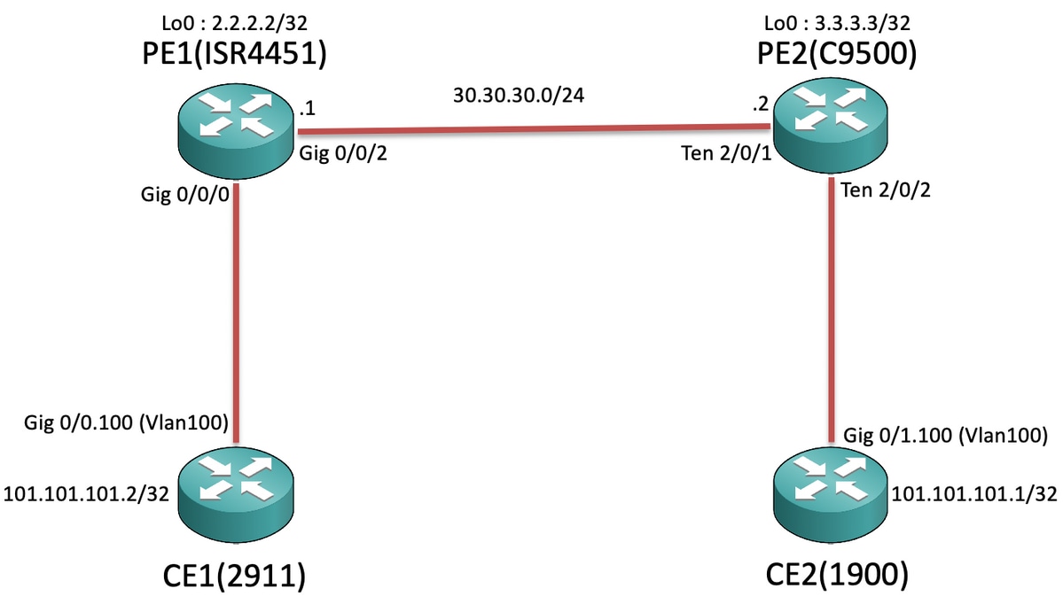
コンフィギュレーション
CE1およびCE2:
CE1#sh run Building configuration... Current configuration : 105 bytes ! interface GigabitEthernet0/0 no ip address duplex auto speed auto ! interface GigabitEthernet0/0.100 encapsulation dot1Q 100 ip address 101.101.101.2 255.255.255.0 ! |
CE2#sh run Building configuration... Current configuration : 1718 bytes ! interface GigabitEthernet0/1 no ip address duplex auto speed auto ! interface GigabitEthernet0/1.100 encapsulation dot1Q 100 ip address 101.101.101.1 255.255.255.0 ! |
PE1およびPE2:
PE1#sh run Building configuration... Current configuration : 5049 bytes ! pseudowire-class VPLS100 encapsulation mpls no control-word ! l2 vfi 100 manual vpn id 100 bridge-domain 100 mtu 9180 neighbor 3.3.3.3 pw-class VPLS100 ! interface Loopback0 ip address 2.2.2.2 255.255.255.255 ! interface GigabitEthernet0/0/0 mtu 9180 no ip address negotiation auto service instance 100 ethernet encapsulation dot1q 100 rewrite ingress tag pop 1 symmetric bridge-domain 100 ! ! interface GigabitEthernet0/0/2 ip address 30.30.30.1 255.255.255.0 negotiation auto mpls ip ! ip route 3.3.3.3 255.255.255.255 30.30.30.2 ! mpls ldp router-id Loopback0 force ! |
PE2#sh run Building configuration... Current configuration : 10722 bytes ! ip routing ! pseudowire-class VPLS100 encapsulation mpls no control-word ! l2 vfi 100 manual vpn id 100 neighbor 2.2.2.2 pw-class VPLS100 ! interface Loopback0 ip address 3.3.3.3 255.255.255.255 ! interface TenGigabitEthernet2/0/1 no switchport ip address 30.30.30.2 255.255.255.0 mpls ip ! interface TenGigabitEthernet2/0/2 switchport trunk allowed vlan 100 switchport mode trunk ! interface Vlan100 no ip address xconnect vfi 100 ! ip route 2.2.2.2 255.255.255.255 30.30.30.1 ! mpls ldp router-id Loopback0 force ! |

注:EFP(Ethernet Flow Point)サービスインスタンスで実行されるISR4KおよびASR1000デバイスでは、サブネット/ブロードキャストドメインを拡張する各SI(サービスインスタンス)で「rewrite ingress tag pop 1 symmetric」コマンドを設定して、ISR4K/ASR1kがCEエンドから送信されるタグ付き(802.1Q Vlan Tag)パケットを受信できるようにします。
確認
Cat9500プラットフォームは、VPLSの下で「イーサネット」とのインターネットワーキングをサポートしています。したがって、最初にVCタイプがイーサネットであることを確認します(デフォルト)。
PE1#show mpls l2transport binding
  Destination Address: 3.3.3.3,VC ID: 100
    Local Label:  19
        Cbit: 0,    VC Type: Ethernet,    GroupID: n/a
        MTU: 9180,   Interface Desc: n/a
        VCCV: CC Type: RA [2], TTL [3]
              CV Type: LSPV [2]
    Remote Label: 17
        Cbit: 0,    VC Type: Ethernet,    GroupID: 0
        MTU: 9180,   Interface Desc: n/a
        VCCV: CC Type: RA [2], TTL [3]
              CV Type: LSPV [2]
PE2#show mpls l2transport binding
  Destination Address: 2.2.2.2,VC ID: 100
    Local Label:  17
        Cbit: 0,    VC Type: Ethernet,    GroupID: n/a
        MTU: 9180,   Interface Desc: n/a
        VCCV: CC Type: RA [2], TTL [3]
              CV Type: LSPV [2]
    Remote Label: 19
        Cbit: 0,    VC Type: Ethernet,    GroupID: 0
        MTU: 9180,   Interface Desc: n/a
        VCCV: CC Type: RA [2], TTL [3]
              CV Type: LSPV [2]
残りのコマンドは、L2VPN VCの確認方法と同様です。ただし、Cat9500にはシステムMTUが設定されているため、LAN側に面する個々のインターフェイスMTU値を変更できないことを理解しておくことが重要です。したがって、ISR4Kプラットフォームのl2 vfiコンテキストで明示的に「mtu <>」を設定し、Cat9500スイッチで設定されたシステムmtuに基づいてMTU値がネゴシエートされるようにする必要があります(デフォルトの設定は無効です)。
PE2:
PE2#show system mtu
Global Ethernet MTU is 9180 bytes.
PE1:
PE1#show mpls l2transport vc detail
Local interface: VFI 100 vfi up
  Interworking type is Ethernet
  Destination address: 3.3.3.3, VC ID: 100, VC status: up
    Output interface: Gi0/0/2, imposed label stack {17}
    Preferred path: not configured
    Default path: active
    Next hop: 30.30.30.2
  Create time: 00:02:10, last status change time: 00:02:10
    Last label FSM state change time: 00:02:10
  Signaling protocol: LDP, peer 3.3.3.3:0 up
    Targeted Hello: 2.2.2.2(LDP Id) -> 3.3.3.3, LDP is UP
    Graceful restart: not configured and not enabled
    Non stop routing: not configured and not enabled
    Status TLV support (local/remote)   : enabled/supported
      LDP route watch                   : enabled
      Label/status state machine        : established, LruRru
      Last local dataplane   status rcvd: No fault
      Last BFD dataplane     status rcvd: Not sent
      Last BFD peer monitor  status rcvd: No fault
      Last local AC  circuit status rcvd: No fault
      Last local AC  circuit status sent: No fault
      Last local PW i/f circ status rcvd: No fault
      Last local LDP TLV     status sent: No fault
      Last remote LDP TLV    status rcvd: No fault
      Last remote LDP ADJ    status rcvd: No fault
    MPLS VC labels: local 19, remote 17
    Group ID: local n/a, remote 0
    MTU: local 9180, remote 9180
    Remote interface description:
  Sequencing: receive disabled, send disabled
  Control Word: Off
  SSO Descriptor: 3.3.3.3/100, local label: 19
  Dataplane:
    SSM segment/switch IDs: 8387/4289 (used), PWID: 4
  VC statistics:
    transit packet totals: receive 0, send 0
    transit byte totals:   receive 0, send 0
    transit packet drops:  receive 0, seq error 0, send 0
PE2:
PE2#show mpls l2transport vc detail
Local interface: VFI 100 vfi up
  Interworking type is Ethernet
  Destination address: 2.2.2.2, VC ID: 100, VC status: up
    Output interface: Te2/0/1, imposed label stack {19}
    Preferred path: not configured
    Default path: active
    Next hop: 30.30.30.1
  Create time: 01:02:03, last status change time: 00:03:09
    Last label FSM state change time: 00:03:09
  Signaling protocol: LDP, peer 2.2.2.2:0 up
    Targeted Hello: 3.3.3.3(LDP Id) -> 2.2.2.2, LDP is UP
    Graceful restart: not configured and not enabled
    Non stop routing: not configured and not enabled
    Status TLV support (local/remote)   : enabled/supported
      LDP route watch                   : enabled
      Label/status state machine        : established, LruRru
      Last local dataplane   status rcvd: No fault
      Last BFD dataplane     status rcvd: Not sent
      Last BFD peer monitor  status rcvd: No fault
      Last local AC  circuit status rcvd: No fault
      Last local AC  circuit status sent: No fault
      Last local PW i/f circ status rcvd: No fault
      Last local LDP TLV     status sent: No fault
      Last remote LDP TLV    status rcvd: No fault
      Last remote LDP ADJ    status rcvd: No fault
    MPLS VC labels: local 17, remote 19
    Group ID: local n/a, remote 0
    MTU: local 9180, remote 9180
    Remote interface description:
  Sequencing: receive disabled, send disabled
  Control Word: Off
  SSO Descriptor: 2.2.2.2/100, local label: 17
  Dataplane:
    SSM segment/switch IDs: 12297/8194 (used), PWID: 1
  VC statistics:
    transit packet totals: receive 0, send 0
    transit byte totals:   receive 0, send 0
    transit packet drops:  receive 0, seq error 0, send 0
CE1からCE2にpingを開始しようとすると、次のようになります。
CE1#ping 101.101.101.1 source 101.101.101.2
Type escape sequence to abort.
Sending 5, 100-byte ICMP Echos to 101.101.101.1, timeout is 2 seconds:
Packet sent with a source address of 101.101.101.2
!!!!!
Success rate is 100 percent (5/5), round-trip min/avg/max = 1/1/4 ms
次に、VC統計情報を調べて、パケットがVPLS経由で送信されていることを確認します。
PE1:
PE1#show mpls l2transport vc detail | sec statistics
  VC statistics:
    transit packet totals: receive 5, send 5
    transit byte totals:   receive 660, send 660
    transit packet drops:  receive 0, seq error 0, send 0
PE2:
PE2#show mpls l2transport vc detail | sec statistics
  VC statistics:
    transit packet totals: receive 5, send 5
    transit byte totals:   receive 680, send 680
    transit packet drops:  receive 0, seq error 0, send 0
トラブルシュート
このドキュメントは、ISR/ASRルータとPEノードとして機能するCat9500スイッチの間でVPLS VCを設定する際の互換性の問題に焦点を当てることを目的としているため、現時点ではトラブルシューティングの手順はありません。
 フィードバック