Comprensión del Uso Compartido de la Carga con BGP en Entornos de Conexión Única/Múltiple
Opciones de descarga
Lenguaje no discriminatorio
El conjunto de documentos para este producto aspira al uso de un lenguaje no discriminatorio. A los fines de esta documentación, "no discriminatorio" se refiere al lenguaje que no implica discriminación por motivos de edad, discapacidad, género, identidad de raza, identidad étnica, orientación sexual, nivel socioeconómico e interseccionalidad. Puede haber excepciones en la documentación debido al lenguaje que se encuentra ya en las interfaces de usuario del software del producto, el lenguaje utilizado en función de la documentación de la RFP o el lenguaje utilizado por un producto de terceros al que se hace referencia. Obtenga más información sobre cómo Cisco utiliza el lenguaje inclusivo.
Acerca de esta traducción
Cisco ha traducido este documento combinando la traducción automática y los recursos humanos a fin de ofrecer a nuestros usuarios en todo el mundo contenido en su propio idioma. Tenga en cuenta que incluso la mejor traducción automática podría no ser tan precisa como la proporcionada por un traductor profesional. Cisco Systems, Inc. no asume ninguna responsabilidad por la precisión de estas traducciones y recomienda remitirse siempre al documento original escrito en inglés (insertar vínculo URL).
Contenido
Introducción
Este documento describe el uso compartido de la carga, que permite que un router distribuya el tráfico saliente y entrante entre varias trayectorias.
Prerequisites
Requirements
Asegúrese de cumplir estos requisitos antes de intentar esta configuración:
-
Conocimiento del Algoritmo de Selección de la Mejor Trayectoria BGP
-
Conocimiento de la configuración de BGP
Componentes Utilizados
Este documento no tiene restricciones específicas en cuanto a versiones de software y de hardware.
La información que contiene este documento se creó a partir de los dispositivos en un ambiente de laboratorio específico. Todos los dispositivos que se utilizan en este documento se pusieron en funcionamiento con una configuración verificada (predeterminada). Si tiene una red en vivo, asegúrese de entender el posible impacto de cualquier comando.
Antecedentes
Las rutas de tráfico entrante y saliente se derivan de forma estática o con protocolos dinámicos como:
-
Routing Information Protocol (RIP)
-
Protocolo de routing de gateway interior mejorado (EIGRP)
-
Protocolo Open Shortest Path First (OSPF)
De forma predeterminada, el protocolo de gateway fronterizo (BGP) selecciona sólo una única ruta óptima y no realiza el equilibrio de carga. Este documento describe cómo realizar el uso compartido de carga en diferentes escenarios con el uso de BGP. Para obtener información adicional sobre el equilibrio de carga, consulte ¿Cómo funciona el equilibrio de carga?.
Carga a Compartir con la Dirección de Loopback como Vecino BGP
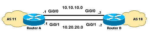
Este escenario muestra cómo lograr el uso compartido de la carga cuando hay varios enlaces de igual costo (hasta un máximo de seis). Los links se terminan en un router en un sistema autónomo local (AS) y en otro router en un AS remoto en un entorno BGP de enlace único. El Diagrama de red sirve como ejemplo.
Diagrama de la red
Esta sección utiliza esta configuración de red:
Configuraciones
Esta sección usa estas configuraciones:
RouterA
interface loopback 0
 ip address 192.168.1.1 255.255.255.255

interface GigabitEthernet0/1
 ip address 10.20.20.1 255.255.255.0

interface GigabitEthernet0/0
 ip address 10.10.10.1 255.255.255.0

router bgp 11
 neighbor 192.168.2.2 remote-as 10
 neighbor 192.168.2.2 update-source loopback 0

!--- Use the IP address of the loopback interface for TCP connections.

neighbor 192.168.2.2 ebgp-multihop

!--- You must configure ebgp-multihop whenever the external BGP (eBGP) connections are not on the same network address.

router eigrp 12
 network 192.168.1.1 0.0.0.0
 network 10.0.0.0
 no auto-summary
RouterB
interface loopback 0
 ip address 192.168.2.2 255.255.255.255

interface GigabitEthernet0/1
 ip address 10.20.20.2 255.255.255.0

interface GigabitEthernet0/0
 ip address 10.10.10.2 255.255.255.0

router bgp 10
 neighbor 192.168.1.1 remote-as 11
 neighbor 192.168.1.1 update-source loopback 0

!--- Use the IP address of the loopback interface for TCP connections.

neighbor 192.168.1.1 ebgp-multihop

!--- You must configure ebgp-multihop whenever the eBGP connections are not on the same network address.

router eigrp 12
 network 192.168.2.2 0.0.0.0
 network 10.0.0.0
 no auto-summary
Nota: Puede utilizar rutas estáticas en lugar de un protocolo de ruteo para introducir dos trayectorias de igual costo para alcanzar el destino. Pero en este ejemplo, se utilizó EIGRP para compartir la información de loopback.
Verificación
Utilice esta sección para confirmar que la configuración funciona correctamente.
El Analizador de Cisco CLI (solo clientes registrados) admite determinados comandos show. Utilice el Analizador de Cisco CLI para ver un análisis de los resultados del comando show.
La salida del comando show ip route muestra ambas trayectorias a la red 192.168.2.2, aprendidas por EIGRP. El comando show ip bgp summary muestra que el vecino BGP se creó con el loopback del router remoto. La salida del comando traceroute indica que la carga se distribuye entre dos links seriales. En esta situación, el uso compartido de la carga se produce por paquete. Puede ejecutar el comando ip route-cache en las interfaces seriales para compartir la carga por destino. También puede configurar el balanceo de carga por paquete y por destino con Cisco Express Forwarding. Para obtener más información sobre cómo configurar Cisco Express Forwarding, consulte Configuración de Cisco Express Forwarding.
RouterA#show ip route Codes: L - local, C - connected, S - static, R - RIP, M - mobile, B - BGP D - EIGRP, EX - EIGRP external, O - OSPF, IA - OSPF inter area N1 - OSPF NSSA external type 1, N2 - OSPF NSSA external type 2 E1 - OSPF external type 1, E2 - OSPF external type 2 i - IS-IS, su - IS-IS summary, L1 - IS-IS level-1, L2 - IS-IS level-2 ia - IS-IS inter area, * - candidate default, U - per-user static route o - ODR, P - periodic downloaded static route, H - NHRP, l - LISP a - application route + - replicated route, % - next hop override, p - overrides from PfR Gateway of last resort is not set 10.0.0.0/8 is variably subnetted, 4 subnets, 2 masks C 10.10.10.0/24 is directly connected, GigabitEthernet0/0 L 10.10.10.1/32 is directly connected, GigabitEthernet0/0 C 10.20.20.0/24 is directly connected, GigabitEthernet0/1 L 10.20.20.1/32 is directly connected, GigabitEthernet0/1 192.168.1.0/32 is subnetted, 1 subnets C 192.168.1.1 is directly connected, Loopback0 192.168.2.0/32 is subnetted, 1 subnets D 192.168.2.2 [90/130816] via 10.20.20.2, 00:02:01, GigabitEthernet0/1 [90/130816] via 10.10.10.2, 00:02:01, GigabitEthernet0/0 RouterA#RouterA#show ip bgp summary BGP router identifier 192.168.1.1, local AS number 11 BGP table version is 1, main routing table version 1 Neighbor V AS MsgRcvd MsgSent TblVer InQ OutQ Up/Down State/PfxRcd 192.168.2.2 4 10 20 20 1 0 0 00:15:05 0RouterA#traceroute 192.168.2.2 Type escape sequence to abort. Tracing the route to 192.168.2.2 VRF info: (vrf in name/id, vrf out name/id) 1 10.10.10.2 2 msec 10.20.20.2 2 msec 10.10.10.2 2 msec RouterA#
Troubleshoot
Actualmente, no hay información específica disponible sobre cómo solucionar los problemas de esta configuración.
Carga compartida cuando se conecta mediante enlace dual a un proveedor de servicios de Internet (ISP) a través de un único router local
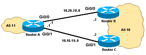
Este escenario muestra cómo lograr compartir la carga cuando existen varios links entre un AS remoto y un AS local. Estos links se terminan en un router en el AS local y en varios routers en AS remotos en un entorno BGP de enlace único. El Diagrama de red es un ejemplo de dicha red.
Esta configuración de muestra utiliza el comando maximum-paths. De forma predeterminada, BGP elige una mejor trayectoria entre las trayectorias de igual costo posibles que se aprenden de un AS. Sin embargo, puede cambiar el número máximo de rutas de igual costo paralelas permitidas. Para realizar este cambio, incluya el comando maximum-paths paths en la configuración de BGP. Utilice un número entre 1 y 6 para el argumento paths.
Diagrama de la red
Esta sección utiliza esta configuración de red:
Configuraciones
Esta sección usa estas configuraciones:
RouterA
interface Loopback0
 ip address 192.168.1.1 255.255.255.255
!
interface GigabitEthernet0/0
 ip address 10.20.20.1 255.255.255.0
!
!
interface GigabitEthernet0/1
 ip address 10.10.10.1 255.255.255.0
!
!
router bgp 11
 neighbor 10.20.20.2 remote-as 10
 neighbor 10.10.10.2 remote-as 10
 network 192.168.1.1 mask 255.255.255.255
 maximum-paths 2

!--- This command specifies the maximum number of paths to install in the routing table for a specific destination.
RouterB
interface GigabitEthernet0/2
 ip address 172.16.2.1 255.255.255.0
!
interface GigabitEthernet0/0
 ip address 10.20.20.2 255.255.255.0
!
!
router bgp 10
 neighbor 10.20.20.1 remote-as 11
 network 172.16.2.0 mask 255.255.255.0
RouterC
interface GigabitEthernet0/2
 ip address 172.16.2.2 255.255.255.0
!
interface GigabitEthernet0/1
 ip address 10.10.10.2 255.255.255.0
!
!
router bgp 10
neighbor 10.10.10.1 remote-as 11
network 172.16.2.0 mask 255.255.255.0
Verificación
Utilice esta sección para confirmar que la configuración funciona correctamente.
El Analizador de Cisco CLI (solo clientes registrados) admite determinados comandos show. Utilice el Analizador de Cisco CLI para ver un análisis de los resultados del comando show.
La salida del comando show ip route muestra que BGP aprende ambas trayectorias a la red 172.16.2.0. La salida del comando traceroute indica que la carga se distribuye entre dos links seriales. En esta situación, el uso compartido de la carga se produce por destino. El comando show ip bgp proporciona las entradas válidas para la red 172.16.2.0.
RouterA#show ip route Codes: L - local, C - connected, S - static, R - RIP, M - mobile, B - BGP D - EIGRP, EX - EIGRP external, O - OSPF, IA - OSPF inter area N1 - OSPF NSSA external type 1, N2 - OSPF NSSA external type 2 E1 - OSPF external type 1, E2 - OSPF external type 2 i - IS-IS, su - IS-IS summary, L1 - IS-IS level-1, L2 - IS-IS level-2 ia - IS-IS inter area, * - candidate default, U - per-user static route o - ODR, P - periodic downloaded static route, H - NHRP, l - LISP a - application route + - replicated route, % - next hop override, p - overrides from PfR Gateway of last resort is not set 10.0.0.0/8 is variably subnetted, 4 subnets, 2 masks C 10.10.10.0/24 is directly connected, GigabitEthernet0/1 L 10.10.10.1/32 is directly connected, GigabitEthernet0/1 C 10.20.20.0/24 is directly connected, GigabitEthernet0/0 L 10.20.20.1/32 is directly connected, GigabitEthernet0/0 172.16.0.0/24 is subnetted, 1 subnets B 172.16.2.0 [20/0] via 10.20.20.2, 00:08:51 [20/0] via 10.10.10.2, 00:08:51 192.168.1.0/32 is subnetted, 1 subnets C 192.168.1.1 is directly connected, Loopback0RouterA#traceroute 172.16.2.2 source loopback0 Type escape sequence to abort. Tracing the route to 172.16.2.2 VRF info: (vrf in name/id, vrf out name/id) 1 10.10.10.2 3 msec 10.20.20.2 3 msec 10.10.10.2 3 msec RouterA#RouterA#show ip bgp BGP table version is 4, local router ID is 192.168.1.1 Status codes: s suppressed, d damped, h history, * valid, > best, i - internal, r RIB-failure, S Stale, m multipath, b backup-path, f RT-Filter, x best-external, a additional-path, c RIB-compressed, t secondary path, Origin codes: i - IGP, e - EGP, ? - incomplete RPKI validation codes: V valid, I invalid, N Not found Network Next Hop Metric LocPrf Weight Path *m 172.16.2.0/24 10.10.10.2 0 0 10 i *> 10.20.20.2 0 0 10 i *> 192.168.1.1/32 0.0.0.0 0 32768 i
Troubleshoot
Actualmente, no hay información específica disponible sobre cómo solucionar los problemas de esta configuración.
Carga a Compartir Cuando Doble Conexión a un ISP A Través de Varios Routers Locales
Este escenario muestra cómo lograr compartir la carga cuando hay varias conexiones al mismo ISP a través de varios routers locales. Los dos peers eBGP terminan en dos routers locales separados. El balanceo de carga en los dos links no es posible porque BGP elige la mejor trayectoria única entre las redes aprendidas de eBGP y BGP interno (iBGP). La distribución de la carga entre las múltiples trayectorias al AS 10 es la mejor opción. Con este tipo de carga compartida, el tráfico a redes específicas, en función de políticas predefinidas, viaja a través de ambos enlaces. Además, cada link actúa como respaldo del otro link, en caso de que uno falle.
Para simplificar, asuma que la política de ruteo BGP para AS 11 es:
-
El AS 11 acepta las rutas locales del AS 10, junto con un valor predeterminado para el resto de las rutas de Internet.
-
La política de tráfico saliente es:
-
Todo el tráfico destinado a Internet desde R101 sale a través del link R101-R103.
-
Si el link R101-R103 falla, entonces todo el tráfico hacia Internet desde R101 irá a través de R102 como AS 10.
-
De manera similar, todo el tráfico destinado a Internet desde R102 pasa a través del link R102-R104.
-
Si el link R102-R104 falla, entonces todo el tráfico hacia Internet desde R102 irá a través de R101 como AS 10.
-
-
La política de tráfico entrante es:
-
El tráfico destinado a la red 192.168.11.0/24 desde Internet proviene del link R103-R101.
-
El tráfico destinado a la red 192.168.12.0/24 desde Internet proviene del link R104-R102.
-
Si un link a AS 10 falla, entonces el otro link rutea el tráfico destinado a todas las redes de regreso a AS 11 desde Internet.
-
Para lograr esto, se anuncia 192.168.11.0 de R101 a R103 con un AS_PATH más corto que el anunciado de R102 a R104. AS 10 encuentra la mejor trayectoria a través del link R103-R101. De manera similar, 192.168.12.0 se anuncia con una trayectoria más corta a través del link R102-R104. El AS 10 prefiere el link R104-R102 para el tráfico enlazado a 192.168.12.0 en el AS 11.
Para el tráfico saliente, BGP determina la mejor trayectoria en base a las rutas aprendidas a través de eBGP. Estas rutas son preferibles a las rutas aprendidas a través de iBGP. R101 aprende 10.10.34.0 de R103 a través de eBGP y de R102 a través de iBGP. La trayectoria externa se selecciona sobre la trayectoria interna. Si observa la tabla BGP en la configuración de R101, la ruta hacia 10.10.34.0 sería a través del link R101-R103, con el salto siguiente 10.10.13.3. En R102, la ruta hacia 10.10.34.0 es a través del link R102-R104, con el salto siguiente 10.10.0 24.4. Esto logra compartir la carga para el tráfico destinado a 10.10.34.0. Una razón similar se aplica a las rutas predeterminadas en R101 y R102. Para obtener más información sobre los criterios de selección de trayectoria BGP, consulte Algoritmo de Selección de Mejor Trayectoria BGP.
Diagrama de la red
Esta sección utiliza esta configuración de red:
Configuraciones
Esta sección usa estas configuraciones:
R101
hostname R101
!
interface Ethernet0/0
 ip address 192.168.11.1 255.255.255.0 secondary
 ip address 192.168.12.1 255.255.255.0
!
interface Serial8/0
 ip address 10.10.13.1 255.255.255.0
!
router bgp 11
 no synchronization
 bgp log-neighbor-changes
 network 192.168.11.0
 network 192.168.12.0
 neighbor 10.10.13.3 remote-as 10
 neighbor 10.10.13.3 route-map R101-103-MAP out

!--- The AS_PATH is increased for 192.168.12.0.

 neighbor 192.168.12.2 remote-as 11
 neighbor 192.168.12.2 next-hop-self
 maximum-paths 2
 no auto-summary
!
access-list 1 permit 192.168.12.0
access-list 2 permit 192.168.11.0
route-map R101-103-MAP permit 10
 match ip address 1
 set as-path prepend 11 11 11
!
route-map R101-103-MAP permit 20
 match ip address 2
R102
hostname R102
!
interface Ethernet0/0
 ip address 192.168.11.2 255.255.255.0 secondary
 ip address 192.168.12.2 255.255.255.0
!
interface Serial8/0
 ip address 10.10.24.2 255.255.255.0
!
router bgp 11
 no synchronization
 bgp log-neighbor-changes
 network 192.168.11.0
 network 192.168.12.0
 neighbor 10.10.24.4 remote-as 10
 neighbor 10.10.24.4 route-map R102-104-MAP out

!--- The AS_PATH is increased for 192.168.11.0.

 neighbor 192.168.12.1 remote-as 11
 neighbor 192.168.12.1 next-hop-self
 no auto-summary
!
access-list 1 permit 192.168.11.0
access-list 2 permit 192.168.12.0
route-map R102-104-MAP permit 10
 match ip address 1
 set as-path prepend 11 11 11
!
route-map R102-104-MAP permit 20
 match ip address 2
R103
hostname R103
!
interface Ethernet0/0
 ip address 10.10.34.3 255.255.255.0
!
interface Serial8/0
 ip address 10.10.13.3 255.255.255.0
!
router bgp 10
no synchronization
 bgp log-neighbor-changes
 network 10.10.34.0 mask 255.255.255.0
 neighbor 10.10.13.1 remote-as 11
 neighbor 10.10.13.1 default-originate
 neighbor 10.10.34.4 remote-as 10
 neighbor 10.10.34.4 next-hop-self
 no auto-summary
R104
hostname R104
!
interface Ethernet0/0
 ip address 10.10.34.4 255.255.255.0
!
interface Serial8/0
 ip address 10.10.24.4 255.255.255.0
!
router bgp 10
 no synchronization
 bgp log-neighbor-changes
 neighbor 10.10.24.2 remote-as 11
 neighbor 10.10.24.2 default-originate
 neighbor 10.10.34.3 remote-as 10
 neighbor 10.10.34.3 next-hop-self
 no auto-summary
Verificación
En esta sección encontrará información que puede utilizar para comprobar que su configuración funcione correctamente.
Ciertos comandos show son soportados por el Cisco CLI Analyzer (sólo clientes registrados) , que le permite ver un análisis del resultado del comando show.
Verificación cuando ambos links entre AS 11 y AS 10 están activados
Verificación de tráfico saliente
Nota: El signo mayor que (>) en el resultado del comando show ip bgp representa la mejor trayectoria a utilizar para esa red entre las trayectorias posibles. Si desea obtener más información, consulte Algoritmo de Selección de la Mejor Trayectoria de BGP.
La tabla BGP en R101 muestra que la mejor trayectoria para todo el tráfico saliente a Internet es a través del link R101-R103. El resultado del comando show ip route confirma las rutas en la tabla de ruteo.
R101#show ip bgp

BGP table version is 5, local router ID is 192.168.12.1
Status codes: s suppressed, d damped, h history, * valid, > best, i - internal
Origin codes: i - IGP, e - EGP, ? - incomplete

   Network          Next Hop            Metric LocPrf Weight Path
* i0.0.0.0          192.168.12.2                  100      0 10 i
*>                  10.10.13.3                             0 10 i
!--- This is the next hop of R103.

* i10.10.34.0/24    192.168.12.2                  100      0 10 i
*>                  10.10.13.3               0             0 10 i
!--- This is the next hop of R103.
* i192.168.11.0     192.168.12.2             0    100      0 i
*>                  0.0.0.0                  0         32768 i
* i192.168.12.0     192.168.12.2             0    100      0 i
*>                  0.0.0.0                  0         32768 i

R101#show ip route

!--- Output suppressed.

Gateway of last resort is 10.10.13.3 to network 0.0.0.0

C    192.168.12.0/24 is directly connected, Ethernet0/0
C    192.168.11.0/24 is directly connected, Ethernet0/0
     10.0.0.0/24 is subnetted, 2 subnets
C       10.10.13.0 is directly connected, Serial8/0
B       10.10.34.0 [20/0] via 10.10.13.3, 00:08:53
!--- This is the next hop of R103.

B*   0.0.0.0/0 [20/0] via 10.10.13.3, 00:08:53
!--- This is the next hop of R103.
Estas son las tablas BGP y de ruteo para R102. Según la política, R102 rutea todo el tráfico a AS 10 a través del link R102-R104:
R102#show ip bgp

BGP table version is 7, local router ID is 192.168.12.2
Status codes: s suppressed, d damped, h history, * valid, > best, i - internal
Origin codes: i - IGP, e - EGP, ? - incomplete

   Network          Next Hop            Metric LocPrf Weight Path
*> 0.0.0.0          10.10.24.4                             0 10 i
!--- This is the next hop of R104.

* i                 192.168.12.1                  100      0 10 i
*> 10.10.34.0/24    10.10.24.4                             0 10 i
!--- This is the next hop of R104.

* i                 192.168.12.1             0    100      0 10 i
* i192.168.11.0     192.168.12.1             0    100      0 i
*>                  0.0.0.0                  0         32768 i
* i192.168.12.0     192.168.12.1             0    100      0 i
*>                  0.0.0.0                  0         32768 i

R102#show ip route

!--- Output suppressed.

Gateway of last resort is 10.10.24.4 to network 0.0.0.0

C    192.168.12.0/24 is directly connected, Ethernet0/0
C    192.168.11.0/24 is directly connected, Ethernet0/0
     10.0.0.0/24 is subnetted, 2 subnets
C       10.10.24.0 is directly connected, Serial8/0
B       10.10.34.0 [20/0] via 10.10.24.4, 00:11:21
!--- This is the next hop of R104.

B*   0.0.0.0/0 [20/0] via 10.10.24.4, 00:11:21
!--- This is the next hop of R104.
Verificación del tráfico entrante de AS 10 a AS 11
Las redes 192.168.11.0 y 192.168.12.0 pertenecen a AS 11. Según la política, AS 11 prefiere el link R103-R101 para el tráfico destinado a la red 192.168.11.0 y el link R104-R102 para el tráfico destinado a la red 192.168.12.0.
R103#show ip bgp

BGP table version is 4, local router ID is 10.10.34.3
Status codes: s suppressed, d damped, h history, * valid, > best, i - internal
Origin codes: i - IGP, e - EGP, ? - incomplete

   Network          Next Hop            Metric LocPrf Weight Path
*> 10.10.34.0/24    0.0.0.0                  0         32768 i
*> 192.168.11.0     10.10.13.1               0             0 11 i
!--- The next hop is R101.
*  192.168.12.0     10.10.13.1               0             0 11 11 11 11 i
*>i                 10.10.34.4               0    100      0 11 i
!--- The next hop is R104.


R103#show ip route

!--- Output suppressed.
Gateway of last resort is not set

B    192.168.12.0/24 [200/0] via 10.10.34.4, 00:04:46
!--- The next hop is R104.

B    192.168.11.0/24 [20/0] via 10.10.13.1, 00:04:46
!--- The next hop is R101.

     10.0.0.0/24 is subnetted, 2 subnets
C       10.10.13.0 is directly connected, Serial8/0
C       10.10.34.0 is directly connected, Ethernet0/0
La mejor trayectoria para la red 192.168.11.0 en R103 es a través del link R103-R101, y la mejor trayectoria para la red 192.168.12.0 es a través de R104 a AS 11. En este caso, la longitud de trayectoria más corta determina la mejor trayectoria.
De manera similar, en R104, la tabla de BGP y de ruteo se asemeja a lo siguiente:
R104#show ip bgp

BGP table version is 13, local router ID is 10.10.34.4
Status codes: s suppressed, d damped, h history, * valid, > best, i - internal
Origin codes: i - IGP, e - EGP, ? - incomplete

   Network          Next Hop            Metric LocPrf Weight Path
*>i10.10.34.0/24    10.10.34.3               0    100      0 i
*>i192.168.11.0     10.10.34.3               0    100      0 11 i
*                   10.10.24.2               0             0 11 11 11 11 i
*> 192.168.12.0     10.10.24.2               0             0 11 i

R104#show ip route

!--- Output suppressed.
Gateway of last resort is not set

B    192.168.12.0/24 [20/0] via 10.10.24.2, 00:49:06
!--- The next hop is R102.

B    192.168.11.0/24 [200/0] via 10.10.34.3, 00:07:36
!--- The next hop is R103.

     10.0.0.0/24 is subnetted, 2 subnets
C       10.10.24.0 is directly connected, Serial8/0
C       10.10.34.0 is directly connected, Ethernet0/0
Verificación cuando falla el link R101-R103
Cuando el link R101-R103 falla, todo el tráfico debe ser re-enrutado a través de R102. Este diagrama ilustra este cambio:
Cierre el link R103-R101 en R103 para simular esta situación.
R103(config)#interface serial 8/0
R103(config-if)#shutdown

*May 1 00:52:33.379: %BGP-5-ADJCHANGE: neighbor 10.10.13.1 Down Interface flap
*May 1 00:52:35.311: %LINK-5-CHANGED: Interface Serial8/0, changed state to administratively down
*May 1 00:52:36.127: %LINEPROTO-5-UPDOWN: Line protocol on Interface Serial8/0, changed state to down
Verificar la ruta de salida a AS 10.
R101#show ip bgp

BGP table version is 17, local router ID is 192.168.12.1
Status codes: s suppressed, d damped, h history, * valid, > best, i - internal
Origin codes: i - IGP, e - EGP, ? - incomplete

   Network          Next Hop            Metric LocPrf Weight Path
*>i0.0.0.0          192.168.12.2                  100      0 10 i
!--- This is the next hop of R102.
*>i10.10.34.0/24    192.168.12.2                  100      0 10 i
!--- This is the next hop of R102.

* i192.168.11.0     192.168.12.2             0    100      0 i
*>                  0.0.0.0                  0         32768 i
* i192.168.12.0     192.168.12.2             0    100      0 i
*>                  0.0.0.0                  0         32768 i

R101#show ip route

!--- Output suppressed.

Gateway of last resort is 192.168.12.2 to network 0.0.0.0

C    192.168.12.0/24 is directly connected, Ethernet0/0
C    192.168.11.0/24 is directly connected, Ethernet0/0
     10.0.0.0/24 is subnetted, 1 subnets
B       10.10.34.0 [200/0] via 192.168.12.2, 00:01:34
B*   0.0.0.0/0 [200/0] via 192.168.12.2, 00:01:34

!--- All outbound traffic goes through R102.

R102#show ip route

!--- Output suppressed.

Gateway of last resort is 10.10.24.4 to network 0.0.0.0

C    192.168.12.0/24 is directly connected, Ethernet0/0
 C    192.168.11.0/24 is directly connected, Ethernet0/0
     10.0.0.0/24 is subnetted, 2 subnets
C       10.10.24.0 is directly connected, Serial8/0
B       10.10.34.0 [20/0] via 10.10.24.4, 00:13:22
B*   0.0.0.0/0 [20/0] via 10.10.24.4, 00:55:22

!--- All outbound traffic on R102 goes through R104.
Verifique la ruta de tráfico entrante cuando R101-R103 está inactivo.
R103#show ip bgp

BGP table version is 6, local router ID is 10.10.34.3
Status codes: s suppressed, d damped, h history, * valid, > best, i - internal
Origin codes: i - IGP, e - EGP, ? - incomplete

   Network          Next Hop            Metric LocPrf Weight Path
*> 10.10.34.0/24    0.0.0.0                  0         32768 i
*>i192.168.11.0     10.10.34.4               0    100      0 11 11 11 11 i
*>i192.168.12.0     10.10.34.4               0    100      0 11 i

R103#show ip route

!--- Output suppressed.
Gateway of last resort is not set

B    192.168.12.0/24 [200/0] via 10.10.34.4, 00:14:55
!--- The next hop is R104.

B    192.168.11.0/24 [200/0] via 10.10.34.4, 00:05:46
!--- The next hop is R104.
     10.0.0.0/24 is subnetted, 1 subnets
C       10.10.34.0 is directly connected, Ethernet0/0
En R104, el tráfico para 192.168.11.0 y 192.168.12.0 pasa a través del link R104-R102.
R104#show ip route

!--- Output suppressed.

Gateway of last resort is not set

B    192.168.12.0/24 [20/0] via 10.10.24.2, 00:58:35
!--- The next hop is R102.

B    192.168.11.0/24 [20/0] via 10.10.24.2, 00:07:57
!--- The next hop is R102.

     10.0.0.0/24 is subnetted, 2 subnets
C       10.10.24.0 is directly connected, Serial8/0
C       10.10.34.0 is directly connected, Ethernet0/0
Troubleshoot
Actualmente, no hay información específica disponible sobre cómo solucionar los problemas de esta configuración.
Distribución de carga desde varias conexiones a dos ISP a través de un único router local.
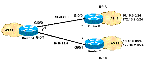
En esta situación, el balanceo de carga no es una opción en un entorno de hosts múltiples, por lo que sólo puede compartir la carga. No puede realizar el balanceo de carga porque BGP selecciona solamente una única mejor trayectoria a un destino entre las rutas BGP aprendidas de los diferentes AS. La idea es establecer una mejor métrica para las rutas en el rango de 1.0.0.x a 128.0.0.x que se aprenden de ISP(A) y una mejor métrica para el resto de las rutas aprendidas de ISP(B). El Diagrama de Red es un ejemplo.
Consulte Configuración de Ejemplo para BGP con Dos Proveedores de Servicio Diferentes (Multihoming) para obtener información adicional.
Diagrama de la red
Esta sección utiliza esta configuración de red:
Configuraciones
Esta sección usa estas configuraciones:
RouterA
interface GigabitEthernet0/0
 ip address 10.20.20.1 255.255.255.0

interface GigabitEthernet0/1
 ip address 10.10.10.1 255.255.255.0

router bgp 11
 neighbor 10.20.20.2 remote-as 10
 neighbor 10.20.20.2 route-map UPDATES-1 in

!--- This allows only the networks up to 128.0.0.x.

neighbor 10.10.10.2 remote-as 12
neighbor 10.10.10.2 route-map UPDATES-2 in

!--- This allows anything above the 128.0.0.x network.

route-map UPDATES-1 permit 10
 match ip address 1
 set weight 100

route-map UPDATES-1 permit 20
 match ip address 2

route-map UPDATES-2 permit 10
 match ip address 1

route-map UPDATES-2 permit 20
 match ip address 2
 set weight 100

access-list 1 permit 0.0.0.0 127.255.255.255
access-list 2 deny 0.0.0.0 127.255.255.255
access-list 2 permit any
RouterB
interface GigabitEthernet0/2
 ip address 172.16.2.1 255.255.255.0

interface GigabitEthernet0/3
 ip address 10.16.6.1 255.255.255.0

interface GigabitEthernet0/0
 ip address 10.20.20.2 255.255.255.0

router bgp 10
 neighbor 10.20.20.1 remote-as 11
 network 172.16.2.0 mask 255.255.255.0
 network 10.16.6.0 mask 255.255.255.0
RouterC
interface GigabitEthernet0/3
 ip address 10.16.6.2 255.255.255.0

interface GigabitEthernet0/2
 ip address 172.16.2.2 255.255.255.0

interface GigabitEthernet0/1
 ip address 10.10.10.2 255.255.255.0

router bgp 12
 neighbor 10.10.10.1 remote-as 11
 network 172.16.2.0 mask 255.255.255.0
 network 10.16.6.0 mask 255.255.255.0
Verificación
Utilice esta sección para confirmar que la configuración funciona correctamente.
El Analizador de Cisco CLI (solo clientes registrados) admite determinados comandos show. Utilice el Analizador de Cisco CLI para ver un análisis de los resultados del comando show.
El resultado del comando show ip route y el resultado del comando traceroute muestran cualquier red inferior a 128.0.0.x que sale del RouterA a 10.20.20.2. Esta ruta es el salto siguiente fuera de la interfaz serial 0. El resto de las redes salen a través de 10.10.10.2, que es el salto siguiente fuera de la interfaz serial 1.
RouterA#show ip route
!--- Output suppressed.
Gateway of last resort is not set
B 172.16.2.0/24 [20/0] via 10.10.10.2, 00:13:16
!--- This is the next hop out through GigabitEthernet0/0.
B 10.16.6.0/24 [20/0] via 10.20.20.2, 00:13:16 !--- This is the next hop out through GigabitEthernet0/1.
!--- Output suppressed.RouterA#show ip cef 172.16.2.0 172.16.2.0/24 nexthop 10.10.10.2 GigabitEthernet0/1 RouterA#show ip cef 10.16.6.0 10.16.6.0/24 nexthop 10.20.20.2 GigabitEthernet0/0RouterA#show ip bgp BGP table version is 10, local router ID is 192.168.1.1 Status codes: s suppressed, d damped, h history, * valid, > best, i - internal, r RIB-failure, S Stale, m multipath, b backup-path, f RT-Filter, x best-external, a additional-path, c RIB-compressed, t secondary path, Origin codes: i - IGP, e - EGP, ? - incomplete RPKI validation codes: V valid, I invalid, N Not found Network Next Hop Metric LocPrf Weight Path *> 10.16.6.0/24 10.20.20.2 0 100 10 i * 10.10.10.2 0 0 12 i * 172.16.2.0/24 10.20.20.2 0 0 10 i *> 10.10.10.2 0 100 12 i *> 192.168.1.1/32 0.0.0.0 0 32768 iRouterA#traceroute 172.16.2.1 source loopback0 Type escape sequence to abort. Tracing the route to 172.16.2.1 VRF info: (vrf in name/id, vrf out name/id) 1 10.10.10.2 2 msec 3 msec 2 msec 2 172.16.2.1 [AS 12] 3 msec 3 msec * RouterA#traceroute 10.16.6.1 source loopback0 Type escape sequence to abort. Tracing the route to 10.16.6.1 VRF info: (vrf in name/id, vrf out name/id) 1 10.20.20.2 3 msec 2 msec * RouterA#
Troubleshoot
Actualmente, no hay información específica disponible sobre cómo solucionar los problemas de esta configuración.
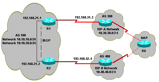
Carga a Compartir cuando se Realiza un Multihomed a Dos ISPs a Través de Varios Routers Locales
El balanceo de carga no es posible en un entorno de hosts múltiples con dos ISP. BGP selecciona solamente la mejor trayectoria única a un destino entre las trayectorias BGP aprendidas de los AS diferentes, lo que hace imposible el balanceo de carga. Sin embargo, la distribución de la carga es posible en este tipo de redes BGP de hosts múltiples. En base a políticas predeterminadas, el flujo de tráfico se controla con diferentes atributos BGP.
Esta sección trata sobre las configuraciones de hosts múltiples que se utilizan con más frecuencia. La configuración muestra cómo lograr compartir la carga. Vea el Diagrama de red, en el cual el multihome del AS 100 logra confiabilidad y carga compartida.
Nota: Las direcciones IP de este ejemplo cumplen con los estándares RFC 1918 para el espacio de direcciones privadas.
Para simplificar, asuma que la política de ruteo BGP para AS 100 es:
-
AS 100 acepta las rutas locales de ambos proveedores, junto con un valor predeterminado para las otras rutas de Internet.
-
La política de tráfico saliente es:
-
El tráfico destinado al AS 300 pasa a través del link R1-ISP(A).
-
El tráfico destinado al AS 400 pasa a través del link R2-ISP(B).
-
El resto del tráfico prefiere la ruta predeterminada 0.0.0.0 a través del link R1-ISP(A).
-
Si el link R1-ISP(A) falla, todo el tráfico pasa a través del link R2-ISP(B).
-
-
La política de tráfico entrante es:
-
El tráfico destinado a la red 10.10.10.0/24 desde Internet proviene del link ISP(A)-R1.
-
El tráfico destinado a la red 10.10.20.0/24 desde Internet proviene del link ISP(B)-R2.
-
Si un ISP falla, el otro ISP enruta el tráfico de regreso al AS 100 desde Internet para todas las redes.
-
Diagrama de la red
Esta sección utiliza esta configuración de red:
Configuraciones
Esta sección usa estas configuraciones:
R2
interface Ethernet0
 ip address 192.168.21.2 255.255.255.0
 !
interface Serial0
  ip address 192.168.42.2 255.255.255.0
router bgp 100
 no synchronization
 bgp log-neighbor-changes

!--- The next two lines announce the networks to BGP peers.

 network 10.10.10.0 mask 255.255.255.0
 network 10.10.20.0 mask 255.255.255.0

!--- The next line configures iBGP on R1.

  neighbor 192.168.21.1 remote-as 100
  neighbor 192.168.21.1 next-hop-self

!--- The next line configures eBGP with ISP(B).

 neighbor 192.168.42.4 remote-as 400

!--- This is the incoming policy route map for the application of attributes to specific routes.

 neighbor 192.168.42.4 route-map AS-400-INCOMING in

!--- This is the outgoing policy route map for the application of attributes to specific routes.

 neighbor 192.168.42.4 route-map AS-400-OUTGOING out
 no auto-summary

!--- This line sets the AS path access list, it permits all routes within the routing domain of the provider.

ip as-path access-list 1 permit ^400$

!--- These two lines set the access list.

access-list 10 permit 10.10.10.0 0.0.0.255
access-list 20 permit 10.10.20.0 0.0.0.255

!--- The next three lines configure LOCAL_PREF for routes that match AS path access list 1.

route-map AS-400-INCOMING permit 10
 match as-path 1
 set local-preference 150

!--- Here, the route map prepends AS 100 to BGP updates for networks that are permitted by access list 10.

route-map AS-400-OUTGOING permit 10
 match ip address 10
 set as-path prepend 100

!--- This line announces the network that is permitted by access list 20 without any changes in BGP attributes.

route-map AS-400-OUTGOING permit 20
 match ip address 20
R1
interface Serial0/0
 ip address 192.168.31.1 255.255.255.0
!
interface Ethernet1/0
 ip address 192.168.21.1 255.255.255.0
!
router bgp 100
 no synchronization
 bgp log-neighbor-changes
 network 10.10.10.0 mask 255.255.255.0
 network 10.10.20.0 mask 255.255.255.0

!--- IBGP peering with R2

neighbor 192.168.21.2 remote-as 100
neighbor 192.168.21.2 next-hop-self

!--- This line sets eBGP peering with ISP(A).

neighbor 192.168.31.3 remote-as 300

!--- This is the incoming policy route map for the application of attributes to specific routes.

 neighbor 192.168.31.3 route-map AS-300-INCOMING in

!--- This is the outgoing policy route map for the application of attributes to specific routes.

neighbor 192.168.31.3 route-map AS-300-OUTGOING out
 no auto-summary

!--- This line sets the AS path access list, it permits all routes within the routing domain of the provider.

ip as-path access-list 1 permit ^300$

!--- These two lines set the IP access list.

access-list 10 permit 10.10.20.0 0.0.0.255
access-list 20 permit 10.10.10.0 0.0.0.255

!--- The next three lines configure LOCAL_PREF for routes that match AS path access list 1.

route-map AS-300-INCOMING permit 10
 match as-path 1
 set local-preference 200

!--- Here, the route map prepends AS 100 to BGP updates for networks that are permitted by access list 10.

route-map AS-300-OUTGOING permit 10
 match ip address 10
 set as-path prepend 100

!--- This line announces the network that is permitted by access list 20 without any changes in BGP attributes.

route-map AS-300-OUTGOING permit 20
 match ip address 20
!
Verificación
Utilice esta sección para confirmar que la configuración funciona correctamente.
El Analizador de Cisco CLI (solo clientes registrados) admite determinados comandos show. Utilice el Analizador de Cisco CLI para ver un análisis de los resultados del comando show.
Ejecute el comando show ip bgp para verificar que la política de salida/entrada funcione.
Nota: El signo mayor a (>) en el resultado del comando show ip bgp representa el mejor trayecto que puede usarse para esa red entre los diversos trayectos posibles. Si desea obtener más información, consulte Algoritmo de Selección de la Mejor Trayectoria de BGP.
R1#show ip bgp

BGP table version is 6, local router ID is 192.168.31.1
Status codes: s suppressed, d damped, h history, * valid, > best, i - internal
Origin codes: i - IGP, e - EGP, ? - incomplete

BGP table version is 6, local router ID is 192.168.31.1
Status codes: s suppressed, d damped, h history, * valid, > best, i - internal
Origin codes: i - IGP, e - EGP, ? - incomplete

Network          Next Hop            Metric LocPrf Weight Path
*> 0.0.0.0          192.168.31.3                  200      0 300 i

!--- This line shows that the default route 0.0.0.0/0 is preferred through AS 300, ISP(A).

* i10.10.10.0/24    192.168.21.2             0    100      0 i
*>                  0.0.0.0                  0         32768 i
* i10.10.20.0/24    192.168.21.2             0    100      0 i
*>                  0.0.0.0                  0         32768 i
*> 10.30.30.0/24    192.168.31.3             0    200      0 300 i
*>i10.40.40.0/24    192.168.21.2             0    150      0 400 i


!--- The route to network 10.30.30.0/24 (AS 300) is preferred through the R1-ISP(A) link.
!--- The route to network 10.40.40.0/24 (AS 400) is preferred through the R2-ISP(B) link.
Ahora, observe la salida show ip bgp en R2:
R2#show ip bgp

BGP table version is 8, local router ID is 192.168.42.2
Status codes: s suppressed, d damped, h history, * valid, > best, i - internal
Origin codes: i - IGP, e - EGP, ? - incomplete

   Network          Next Hop            Metric LocPrf Weight Path
*  0.0.0.0          192.168.42.4                  150      0 400 i
*>i                 192.168.21.1                  200      0 300 i

!--- This line shows that the default route 0.0.0.0/0 is preferred through AS 300, through the R2-ISP(B) link.

*> 10.10.10.0/24    0.0.0.0                  0         32768 i
* i                 192.168.21.1             0    100      0 i
*> 10.10.20.0/24    0.0.0.0                  0         32768 i
* i                 192.168.21.1             0    100      0 i
*>i10.30.30.0/24    192.168.21.1             0    200      0 300 i
*> 10.40.40.0/24    192.168.42.4             0    150      0 400 i

!--- The route to network 10.30.30.0/24 (AS 300) is preferred through the R1-ISP(A) link.
!--- The route to network 10.40.40.0/24 (AS 400) is preferred through the R2-ISP(B) link.
Ejecute el comando show ip bgp en el router 6 para observar la política entrante para las redes 10.10.10.0/24 y 10.10.20.0/24:
R6#show ip bgp

BGP table version is 15, local router ID is 192.168.64.6
Status codes: s suppressed, d damped, h history, * valid, > best, i - internal
Origin codes: i - IGP, e - EGP, ? - incomplete

   Network          Next Hop            Metric LocPrf Weight Path
*> 10.10.10.0/24    192.168.63.3                           0 300 100 100 i

!--- This line shows that network 10.10.10.0/24 is routed through AS 300
!--- with the ISP(A)-R1 link.

*                   192.168.64.4                           0 400 100 100 100 i
*  10.10.20.0/24    192.168.63.3                           0 300 100 100 i
*>                  192.168.64.4                           0 400 100 i

!--- This line shows that network 10.10.20.0/24 is routed through AS 400
!--- with the ISP(B)-R2 link.

*> 10.30.30.0/24    192.168.63.3             0             0 300 i
*> 10.40.40.0/24    192.168.64.4             0             0 400 i
Apague el link R1-ISP(A) en R1 y observe la tabla BGP. Espere que todo el tráfico a Internet se enrute a través del link R2-ISP(B):
R1(config)#interface serial 0/0
R1(config-if)#shutdown

*May  2 19:00:47.377: %BGP-5-ADJCHANGE: neighbor 192.168.31.3 Down Interface flap
*May  2 19:00:48.277: %LINK-5-CHANGED: Interface Serial0/0, changed state to
 administratively  down
*May 23 12:00:51.255: %LINEPROTO-5-UPDOWN: Line protocol on Interface Serial0, changed
 state to down

R1#show ip bgp

BGP table version is 12, local router ID is 192.168.31.1
Status codes: s suppressed, d damped, h history, * valid, > best, i - internal
Origin codes: i - IGP, e - EGP, ? - incomplete

   Network          Next Hop            Metric LocPrf Weight Path
*>i0.0.0.0          192.168.21.2                  150      0 400 i

!--- The best default path is now through the R2-ISP(B) link.

* i10.10.10.0/24    192.168.21.2             0    100      0 i
*>                  0.0.0.0                  0         32768 i
* i10.10.20.0/24    192.168.21.2             0    100      0 i
*>                  0.0.0.0                  0         32768 i
*>i10.40.40.0/24    192.168.21.2             0    150      0 400 i

R2#show ip bgp

BGP table version is 14, local router ID is 192.168.42.2
Status codes: s suppressed, d damped, h history, * valid, > best, i - internal
Origin codes: i - IGP, e - EGP, ? - incomplete

   Network          Next Hop            Metric LocPrf Weight Path
*> 0.0.0.0          192.168.42.4                  150      0 400 i

!--- The best default route is now through ISP(B) with a local preference of 150.

* i10.10.10.0/24    192.168.21.1             0    100      0 i
*>                  0.0.0.0                  0         32768 i
* i10.10.20.0/24    192.168.21.1             0    100      0 i
*>                  0.0.0.0                  0         32768 i
*> 10.40.40.0/24    192.168.42.4             0    150      0 400 i
Mire la ruta para la red 10.10.10.0/24 en el router 6:
R6#show ip bgp

BGP table version is 14, local router ID is 192.168.64.6
Status codes: s suppressed, d damped, h history, * valid, > best, i - internal
Origin codes: i - IGP, e - EGP, ? - incomplete

   Network          Next Hop            Metric LocPrf Weight Path
*> 10.10.10.0/24    192.168.64.4                           0 400 100 100 i

!--- Network 10.10.10.0 is reachable through ISP(B), which announced the network with AS path prepend.

*> 10.10.20.0/24    192.168.64.4                           0 400 100 i

*> 10.30.30.0/24    192.168.63.3             0             0 300 i
*> 10.40.40.0/24    192.168.64.4             0             0 400 i
Troubleshoot
Actualmente, no hay información específica disponible sobre cómo solucionar los problemas de esta configuración.
Información Relacionada
- BGP Multi-Homing: Diseño y resolución de problemas - Vídeo del webcast en directo
- BGP Multi-Homing: Diseño y resolución de problemas: preguntas y respuestas del webcast en directo
- ¿Cómo funciona el balanceo de cargas?
- Ejemplo de Configuración de BGP con Dos Proveedores de Servicio Diferentes (Multihoming)
- Cómo los Routers BGP Utilizan el Discriminador de Salida Múltiple para la Selección de la Mejor Trayectoria
- Página de soporte de la tecnología de routing IP
- Soporte Técnico y Documentación - Cisco Systems
Historial de revisiones
| Revisión | Fecha de publicación | Comentarios |
|---|---|---|
4.0 |
26-Feb-2025
|
SEO actualizado. |
3.0 |
30-Aug-2023
|
Título actualizado, información de fondo, requisitos de estilo y formato. |
2.0 |
21-Jul-2022
|
Recertificación |
1.0 |
10-Dec-2001
|
Versión inicial |
Con la colaboración de ingenieros de Cisco
- Cisco TAC Engineers
 Comentarios
Contacte a Cisco
- Abrir un caso de soporte

- (Requiere un Cisco Service Contract)