- Preface
- Chapter 1 - Product Overview
- Chapter 2 - Preparing for Installation
- Chapter 3 - Installing the Client Adapter
- Chapter 4 - Using the Profile Manager
- Chapter 5 - Configuring the Client Adapter
- Chapter 6 - Using EAP Authentication
- Chapter 7 - Performing Diagnostics
- Chapter 8 - Using the Aironet Client Monitor (ACM)
- Chapter 9 - Routine Procedures
- Chapter 10 - Troubleshooting
- Appendix A - Technical Specifications
- Appendix B - Translated Safety Warnings
- Appendix C - Declarations of Conformity and Regulatory Information
- Appendix D - Channels, Power Levels, and Antenna Gains
- Appendix E - Configuring the Client Adapter through Windows XP
- Appendix F - Performing a Site Survey
- Glossary
- Index
Cisco Aironet 340, 350, and CB20A Wireless LAN Client Adapters Installation and Configuration Guide for Windows, OL-1394-06
Bias-Free Language
The documentation set for this product strives to use bias-free language. For the purposes of this documentation set, bias-free is defined as language that does not imply discrimination based on age, disability, gender, racial identity, ethnic identity, sexual orientation, socioeconomic status, and intersectionality. Exceptions may be present in the documentation due to language that is hardcoded in the user interfaces of the product software, language used based on RFP documentation, or language that is used by a referenced third-party product. Learn more about how Cisco is using Inclusive Language.
- Updated:
- May 4, 2007
Chapter: Chapter 1 - Product Overview
Product Overview
This chapter describes the Cisco Aironet Wireless LAN Client Adapters and illustrates their role in a wireless network.
The following topics are covered in this chapter:
•![]() Introduction to the Client Adapters
Introduction to the Client Adapters
•![]() Network Configurations Using Client Adapters
Network Configurations Using Client Adapters
Introduction to the Client Adapters
The Cisco Aironet Wireless LAN Client Adapters are radio modules that provide transparent wireless data communications between fixed, portable, or mobile devices and other wireless devices or a wired network infrastructure. The client adapters are fully compatible when used in devices supporting Plug-and-Play (PnP) technology.
The primary function of the client adapters is to transfer data packets transparently through the wireless infrastructure through an access point connected to a wired LAN. The adapters operate similarly to a standard network product except that the cable is replaced with a radio connection and an access point is required to make the connection to the wire. No special wireless networking functions are required, and all existing applications that operate over a network can operate using the adapters.
This document covers the five client adapters described in Table 1-1.


Note ![]() In the first three product model numbers, the first x represents the client adapter series (340 or 350), and the second x indicates the wired equivalent privacy (WEP) level of the card, where 0 = no WEP capability, 1 = 40-bit WEP, and 2 = 128-bit WEP. If the last two product model numbers contain K9, the card is 128-bit WEP capable.
In the first three product model numbers, the first x represents the client adapter series (340 or 350), and the second x indicates the wired equivalent privacy (WEP) level of the card, where 0 = no WEP capability, 1 = 40-bit WEP, and 2 = 128-bit WEP. If the last two product model numbers contain K9, the card is 128-bit WEP capable.
Terminology
The following terms are used throughout this document:
•![]() client adapter—Refers to all five types of adapters.
client adapter—Refers to all five types of adapters.
•![]() PC card, LM card, PCI card, mini PCI card, or PC-Cardbus card—Refers to a specific adapter.
PC card, LM card, PCI card, mini PCI card, or PC-Cardbus card—Refers to a specific adapter.
•![]() workstation (or station)—Refers to a computing device with an installed client adapter.
workstation (or station)—Refers to a computing device with an installed client adapter.
•![]() infrastructure device—Refers to a device that connects client adapters to a wired LAN, such as an access point, bridge, or base station. Throughout this document, access point is used to represent infrastructure devices in general.
infrastructure device—Refers to a device that connects client adapters to a wired LAN, such as an access point, bridge, or base station. Throughout this document, access point is used to represent infrastructure devices in general.
Hardware Components
The client adapter has three major hardware components: a radio, a radio antenna, and two LEDs.
Radio
Different radios are used for the 2.4-GHz and 5-GHz client adapters:
•![]() The Cisco Aironet 340 and 350 series PC, LM, PCI, and mini PCI cards are IEEE 802.11b-compliant client adapters. They contain a direct-sequence spread spectrum (DSSS) radio that operates in the 2.4-GHz Industrial Scientific Medical (ISM) license-free band. The 340 series 30-milliwatt (mW) radio and the 350 series 100-mW radio transmit data over a half-duplex radio channel operating at up to 11 Mbps. These cards operate with other IEEE 802.11b-compliant client devices in ad hoc (or peer-to-peer) mode or with Cisco Aironet 340, 350, 1100, and 1200 Series Access Points (with a 2.4-GHz radio) and other IEEE 802.11b-compliant infrastructure devices in infrastructure mode. They are approved for indoor and outdoor use.
The Cisco Aironet 340 and 350 series PC, LM, PCI, and mini PCI cards are IEEE 802.11b-compliant client adapters. They contain a direct-sequence spread spectrum (DSSS) radio that operates in the 2.4-GHz Industrial Scientific Medical (ISM) license-free band. The 340 series 30-milliwatt (mW) radio and the 350 series 100-mW radio transmit data over a half-duplex radio channel operating at up to 11 Mbps. These cards operate with other IEEE 802.11b-compliant client devices in ad hoc (or peer-to-peer) mode or with Cisco Aironet 340, 350, 1100, and 1200 Series Access Points (with a 2.4-GHz radio) and other IEEE 802.11b-compliant infrastructure devices in infrastructure mode. They are approved for indoor and outdoor use.
DSSS technology distributes a radio signal over a wide range of frequencies and then returns the signal to the original frequency range at the receiver. The benefit of this technology is its ability to protect the data transmission from interference. For example, if a particular frequency encounters noise or interference or both, enough redundancy is built into the signal on other frequencies that the client adapter usually will still be successful in its transmission.
•![]() The Cisco Aironet AIR-CB20A PC-Cardbus card is an IEEE 802.11a-compliant client adapter. It contains an orthogonal frequency division multiplexing (OFDM) radio that operates in the Unlicensed National Information Infrastructure (UNII) 1 and UNII 2 license-free bands located in the lower 5-GHz portion of the radio frequency spectrum. The 20-mW radio transmits data over a half-duplex radio channel operating at up to 54 Mbps. This card interoperates with other IEEE 802.11a-compliant client devices in ad hoc mode or with Cisco Aironet 1200 Series Access Points (with a 5-GHz radio) and other IEEE 802.11a-compliant infrastructure devices in infrastructure mode. It is approved for indoor use only except in the United States, which allows for outdoor use on channels 52 through 64.
The Cisco Aironet AIR-CB20A PC-Cardbus card is an IEEE 802.11a-compliant client adapter. It contains an orthogonal frequency division multiplexing (OFDM) radio that operates in the Unlicensed National Information Infrastructure (UNII) 1 and UNII 2 license-free bands located in the lower 5-GHz portion of the radio frequency spectrum. The 20-mW radio transmits data over a half-duplex radio channel operating at up to 54 Mbps. This card interoperates with other IEEE 802.11a-compliant client devices in ad hoc mode or with Cisco Aironet 1200 Series Access Points (with a 5-GHz radio) and other IEEE 802.11a-compliant infrastructure devices in infrastructure mode. It is approved for indoor use only except in the United States, which allows for outdoor use on channels 52 through 64.
Radio Antenna
The type of antenna used depends on your client adapter:
•![]() PC cards have an integrated, permanently attached diversity antenna. The benefit of the diversity antenna system is improved coverage. The system works by allowing the card to switch and sample between its two antenna ports in order to select the optimum port for receiving data packets. As a result, the card has a better chance of maintaining the radio frequency (RF) connection in areas of interference. The antenna is housed within the section of the card that hangs out of the PC card slot when the card is installed.
PC cards have an integrated, permanently attached diversity antenna. The benefit of the diversity antenna system is improved coverage. The system works by allowing the card to switch and sample between its two antenna ports in order to select the optimum port for receiving data packets. As a result, the card has a better chance of maintaining the radio frequency (RF) connection in areas of interference. The antenna is housed within the section of the card that hangs out of the PC card slot when the card is installed.
•![]() LM cards are shipped without an antenna; however, an antenna can be connected through the card's external connector.
LM cards are shipped without an antenna; however, an antenna can be connected through the card's external connector.
•![]() PCI cards are shipped with a 2-dBi dipole antenna that attaches to the card's antenna connector. However, other types of antennas may be used. PCI cards can be operated through only the primary (or right) antenna port.
PCI cards are shipped with a 2-dBi dipole antenna that attaches to the card's antenna connector. However, other types of antennas may be used. PCI cards can be operated through only the primary (or right) antenna port.
•![]() Mini PCI cards are designed to be used with either one or two antennas, which connect to the card's two antenna connectors. If two antennas are used, the radio automatically selects the antenna that presents the best RF signal. If only one antenna is used, the radio finds and uses it regardless of which connector it is plugged into.
Mini PCI cards are designed to be used with either one or two antennas, which connect to the card's two antenna connectors. If two antennas are used, the radio automatically selects the antenna that presents the best RF signal. If only one antenna is used, the radio finds and uses it regardless of which connector it is plugged into.
•![]() PC-Cardbus cards have an integrated, permanently attached non-diversity antenna that contains two antenna ports, one for transmitting and one for receiving. The card cannot switch and sample between the ports. The antenna is housed within the section of the card that hangs out of the Cardbus slot when the card is installed.
PC-Cardbus cards have an integrated, permanently attached non-diversity antenna that contains two antenna ports, one for transmitting and one for receiving. The card cannot switch and sample between the ports. The antenna is housed within the section of the card that hangs out of the Cardbus slot when the card is installed.
Note ![]() Refer to the Antenna Mode (Transmit and Receive) parameters in Table 5-4 and Table 5-5 for information on setting the client adapter's antenna mode.
Refer to the Antenna Mode (Transmit and Receive) parameters in Table 5-4 and Table 5-5 for information on setting the client adapter's antenna mode.
Note ![]() External antennas used in combination with a power setting resulting in a radiated power level above 100 mW equivalent isotropic radiated power (EIRP) are not allowed for use within the European community and other countries that have adopted the European R&TTE directive or the CEPT recommendation Rec 70.03 or both. For more details on legal combinations of power levels and antennas in those countries, refer to the "Declaration of Conformity with Regard to the R&TTE Directive 1999/5/EC" section and the "Maximum Power Levels and Antenna Gains" section.
External antennas used in combination with a power setting resulting in a radiated power level above 100 mW equivalent isotropic radiated power (EIRP) are not allowed for use within the European community and other countries that have adopted the European R&TTE directive or the CEPT recommendation Rec 70.03 or both. For more details on legal combinations of power levels and antennas in those countries, refer to the "Declaration of Conformity with Regard to the R&TTE Directive 1999/5/EC" section and the "Maximum Power Levels and Antenna Gains" section.
LEDs
The client adapters have two LEDs that glow or blink to indicate the status of the adapter or to convey error messages. Refer to Chapter 10, for an interpretation of the LED codes.
Note ![]() Mini PCI cards do not have LEDs.
Mini PCI cards do not have LEDs.
Software Components
The client adapter has three major software components: radio firmware, a driver, and client utilities. These components are installed together by running a single Install Wizard file that is available from Cisco.com. This file can be run on Windows 98, 98 SE, NT, 2000, Me, or XP and can be used with any of the following client adapter types:
•![]() 340 and 350 series PC, LM, and PCI cards
340 and 350 series PC, LM, and PCI cards
•![]() 350 series mini PCI cards
350 series mini PCI cards
•![]() PC-Cardbus (CB20A) cards
PC-Cardbus (CB20A) cards
Chapter 3, provides instructions on using the Install Wizard to install or upgrade these software components.
Note ![]() Prior to the release of the Install Wizard file, each software component had to be installed separately. This version of the Cisco Aironet Wireless LAN Client Adapters Installation and Configuration Guide for Windows pertains specifically to versions of the software that are available through the Install Wizard. If you are using, installing, or upgrading to versions of client adapter software that do not use the Install Wizard, refer to version OL-1394-04 of this manual for information and instructions.
Prior to the release of the Install Wizard file, each software component had to be installed separately. This version of the Cisco Aironet Wireless LAN Client Adapters Installation and Configuration Guide for Windows pertains specifically to versions of the software that are available through the Install Wizard. If you are using, installing, or upgrading to versions of client adapter software that do not use the Install Wizard, refer to version OL-1394-04 of this manual for information and instructions.
Radio Firmware
The firmware controls the client adapter's radio. The client adapter is shipped with the firmware installed in Flash memory. However, Cisco recommends that you always use the latest version. You can upgrade the client adapter's firmware in three ways:
•![]() Through the Install Wizard—The Install Wizard automatically upgrades the client adapter's firmware to the version included in the Install Wizard file.
Through the Install Wizard—The Install Wizard automatically upgrades the client adapter's firmware to the version included in the Install Wizard file.
•![]() Through the driver—The driver included in the Install Wizard file is also bundled with client adapter firmware. Each time you insert a client adapter or reboot your computer, the driver loads and may install the firmware with which it is bundled (if that firmware is newer than the firmware that is currently installed in the adapter). You can use the Install Wizard's Disable Firmware Checking parameter or ACU's Automatically Load New Firmware When NDIS Driver Is Updated parameter to specify whether the driver upgrades the firmware. Refer to page 6 and page 10 for more information.
Through the driver—The driver included in the Install Wizard file is also bundled with client adapter firmware. Each time you insert a client adapter or reboot your computer, the driver loads and may install the firmware with which it is bundled (if that firmware is newer than the firmware that is currently installed in the adapter). You can use the Install Wizard's Disable Firmware Checking parameter or ACU's Automatically Load New Firmware When NDIS Driver Is Updated parameter to specify whether the driver upgrades the firmware. Refer to page 6 and page 10 for more information.
•![]() Through ACU—The Load Firmware icon or Load New Firmware menu option in ACU enables you to upgrade the client adapter's firmware from an image (*.img) file that contains only firmware. Refer to the "Upgrading the Firmware" section for more information.
Through ACU—The Load Firmware icon or Load New Firmware menu option in ACU enables you to upgrade the client adapter's firmware from an image (*.img) file that contains only firmware. Refer to the "Upgrading the Firmware" section for more information.
Driver
The driver provides an interface between a computer running a Windows operating system and the client adapter, thereby enabling Windows and the applications it runs to communicate with the adapter. The driver must be installed before the adapter can be used.
Client Utilities
Two client utilities are available for use with Cisco Aironet client adapters: Aironet Client Utility (ACU) and Aironet Client Monitor (ACM). These utilities are optional applications that interact with the radio firmware to adjust client adapter settings and display information about the adapter.
ACU enables you to create configuration profiles for your client adapter and perform user-level diagnostics. Because ACU performs a variety of functions, it is documented by function throughout this manual. However, an overview of the utility is provided below to familiarize you with its interface.
ACM, which is accessible from an icon in the Windows system tray, provides a small subset of the features available through ACU. Specifically, it enables you to access status information about your client adapter and perform basic tasks. Chapter 8, provides detailed information and instructions on using ACM.
Note ![]() If your computer is running Windows XP, you can configure your client adapter through the Windows operating system instead of through ACU. Refer to Appendix E, for information. However, ACU is recommended for configuring the client adapter.
If your computer is running Windows XP, you can configure your client adapter through the Windows operating system instead of through ACU. Refer to Appendix E, for information. However, ACU is recommended for configuring the client adapter.
Overview of ACU
The Aironet Client Utility screen (see Figure 1-1) is ACU's primary screen.
Figure 1-1 Aironet Client Utility Screen
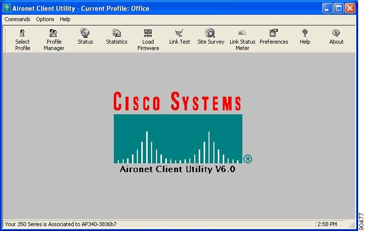
The title bar at the top of the Aironet Client Utility screen shows the profile that is being used by the client adapter.
The status bar at the bottom of the Aironet Client Utility screen reflects the current state of your client adapter. The following states are possible, where radio_name is the client adapter type and ap_name is the configured name of an access point:
•![]() Your radio_name is Associated to ap_name
Your radio_name is Associated to ap_name
•![]() Your radio_name is Not Associated!
Your radio_name is Not Associated!
•![]() Authentication Started with ap_name
Authentication Started with ap_name
•![]() Your radio_name is Authenticated to ap_name
Your radio_name is Authenticated to ap_name
•![]() Authentication Failed with ap_name
Authentication Failed with ap_name
•![]() Your radio_name is in AdHoc Mode
Your radio_name is in AdHoc Mode
•![]() Your radio_name is being loaded with new firmware!
Your radio_name is being loaded with new firmware!
•![]() The radio in your radio_name is turned OFF!
The radio in your radio_name is turned OFF!
•![]() Unable to read the status from your Wireless LAN Adapter!
Unable to read the status from your Wireless LAN Adapter!
•![]() Your radio_name has a problem!
Your radio_name has a problem!
Note ![]() Some 340 series cards may improperly display a radio_name of 4800.
Some 340 series cards may improperly display a radio_name of 4800.
Note ![]() Aironet Extensions must be enabled on access points running Cisco IOS release 12.2(4)JA or greater in order for the ap_name to appear in the status bar.
Aironet Extensions must be enabled on access points running Cisco IOS release 12.2(4)JA or greater in order for the ap_name to appear in the status bar.
The information shown in the status bar is updated once per second.
The right side of the status bar shows the current time of day. If you set the clock to display seconds in the Aironet Client Utility Preferences screen, the time includes seconds in addition to hours and minutes.
Note ![]() To enable the clock to display seconds, open ACU, click the Preferences icon or select Preferences from the Options drop-down menu, check the Display Seconds on Clock check box, and click OK.
To enable the clock to display seconds, open ACU, click the Preferences icon or select Preferences from the Options drop-down menu, check the Display Seconds on Clock check box, and click OK.
Buttons on the ACU Screens
The buttons on the ACU screens are used to perform specific functions. Table 1-2 describes the most common buttons.
Network Configurations Using Client Adapters
Client adapters can be used in a variety of network configurations. In some configurations, access points provide connections to your network or act as repeaters to increase wireless communication range. The maximum communication range is based on how you configure your wireless network.
This section describes and illustrates the two most common network configurations:
•![]() Ad hoc wireless local area network (LAN)
Ad hoc wireless local area network (LAN)
•![]() Wireless infrastructure with workstations accessing a wired LAN
Wireless infrastructure with workstations accessing a wired LAN
For examples of more complex network configurations involving client adapters and access points, refer to the documentation for your access point.
Note ![]() Refer to Chapter 5, for information on setting the client adapter's network mode.
Refer to Chapter 5, for information on setting the client adapter's network mode.
Ad Hoc Wireless LAN
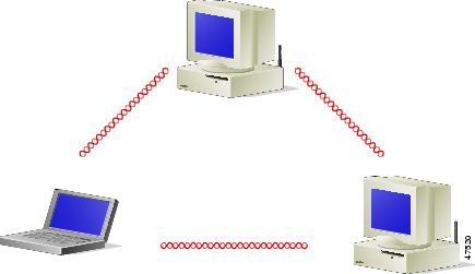
An ad hoc (or peer-to-peer) wireless LAN (see Figure 1-2) is the simplest wireless LAN configuration. In a wireless LAN using an ad hoc network configuration, all devices equipped with a client adapter can be linked together and communicate directly with each other. The use of an infrastructure device, such as an access point, is not required.
Figure 1-2 Ad Hoc Wireless LAN
Wireless Infrastructure with Workstations Accessing a Wired LAN
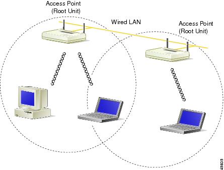
A microcellular network can be created by placing two or more access points on a LAN. Figure 1-3 shows a microcellular network with workstations accessing a wired LAN through several access points.
This configuration is useful with portable or mobile stations because it allows them to be directly connected to the wired network even while moving from one microcell domain to another. This process is transparent, and the connection to the file server or host is maintained without disruption. The mobile station stays connected to an access point as long as it can. However, once the transfer of data packets needs to be retried or beacons are missed, the station automatically searches for and associates to another access point. This process is referred to as seamless roaming.
Figure 1-3 Wireless Infrastructure with Workstations Accessing a Wired LAN
 Feedback