Introduction
This document introduces ATF (Air Time Fairness) feature, and provides general guidelines for its deployment. The purpose of this document is to:
-
Provide an overview of ATF feature, and its deployment within the Cisco Unified Architecture.
-
Highlight key Service Provider features
Introduction to Air Time Fairness (ATF) Phase 1
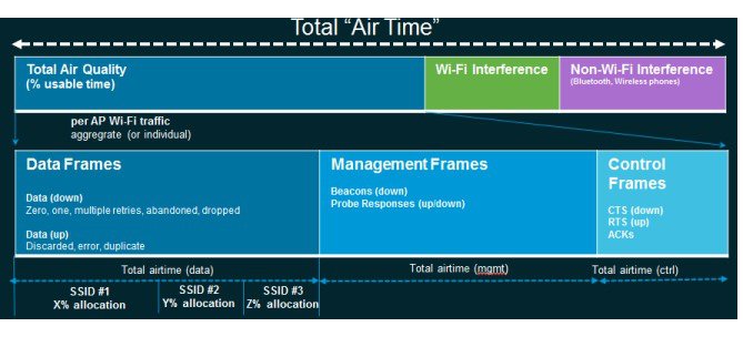
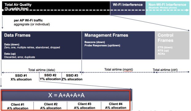
Traditional (wired) implementations of QOS regulate egress bandwidth. With wireless networking, the transmission medium is via radio waves that transmit data at varying rates. Instead of regulating egress bandwidth, it makes more sense to regulate the amount of airtime needed to transmit frames. Air Time Fairness (ATF) is a form of wireless QOS that regulates downlink airtime (as opposed to egress bandwidth). Large scale, high density Wi-Fi deployments are driving this feature. Wireless Network owners are mandating that their applications be allocated some fixed percentage of the total bandwidth of the Wi-Fi network. At the same time, with capital sharing being considered with multiple cellular providers, ATF is needed to ensure fairness of usage across operators.
Cisco Air Time Fairness (ATF) Use Cases
Public Hotspots (Stadium/Airport/Convention Center/Other)
In this instance a public network is sharing a WLAN between two (or more) service providers and the venue. Subscribers to each service provider can be grouped and each group can be allocated a certain percentage of airtime.
Education
In this instance, a university is sharing a WLAN between students, faculty, and guests. The guest network can be further partitioned by service provider. Each group can be assigned a certain percentage of airtime.
Enterprise or Hospitality or Retail
In this instance, the venue is sharing a WLAN between employees and guests. The guest network can be further partitioned by service provider. The guests could be sub-grouped by tier of service type with each subgroup being assigned a certain percentage of airtime, for example a paid group is entitled to more airtime than the free group.
Time Shared Managed Hotspot
In this instance, the business entity managing the hotspot, such as a service provider or an enterprise, can allocate and subsequently lease airtime to other business entities.
ATF Functionality and Capabilities
-
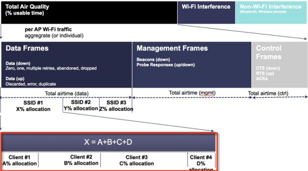
ATF policies are applied only in the downlink direction (AP transmitting frames to client). Only airtime in the downlink direction, that is AP to client, can be controlled accurately by the AP. Although airtime in the uplink direction, that is client to AP, can be measured, it cannot be strictly controlled. Although the AP can constrain airtime for packets that it sends to clients, the AP can only measure airtime for packets that it ‘hears’ from clients because it cannot strictly limit their airtime.
-
ATF policies are applied only on wireless data frames; management and control frames gets ignored.
-
When ATF is configured per-SSID, each SSID is granted airtime according to the configured policy.
-
ATF can be configured to either drop or defer frames that exceed their airtime policies. If the frame is deferred, it will be buffered and transmit at some point in the future when the offending SSID has a sufficient airtime budget. Of course, there is a limit as to how many frames can be buffered. If this limit is crossed, frames will be dropped regardless.
-
ATF can be globally enabled or disabled
-
ATF can be enabled or disabled on an individual access point, AP group or entire network
-
ATF is supported in release 8.4 on the 1260, 1700, 2600, 2700, 3600, 3500, 3700, 1550-128mb, and 1570 series access points in local and FlexConnect mode.
-
ATF on Mesh is supported in release 8.4 on 1550-128mb, 1560, 1570 and 3700 series MAPs.
-
ATF results and statistics are available on the wireless controller.
ATF Modes of Operation
The Framework behind the ATF monitor mode is to allow the user to view and get the stats of overall Air Time being used i.e. to report the Air Time usage for all the AP transmissions. The ATF in monitor mode can be enabled on following levels.
-
Disable Mode: By default ATF is disabled on the WLC
-
Monitor Mode: To monitor airtime usage on your network
-
Enforce—Policy Mode: Assigning ATF policies on your network
-
Strict Enforcement
-
Optimized
-
Monitor Mode Configuration
-
Per AP
-
Per AP Group
-
Network (all APs)
To configure ATF in monitor mode, perform the following steps:
Procedure
|
Step 1 |
Choose WIRELESS > ATF > Monitor Configuration from WLC's main menu bar. |
|
Step 2 |
Select AP Name or AP Group Name or Network (all the APs on that particular WLC). |
|
Step 3 |
Select radio type 802.11a (5 GHz) or 802.11b (2.4 GHz) or both. 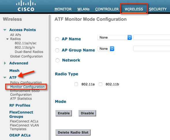 |
Per AP Monitoring Configuration
For AP monitoring configuration, perform the following steps
Procedure
|
Step 1 |
Click AP Name and from the drop down menu choose the AP. 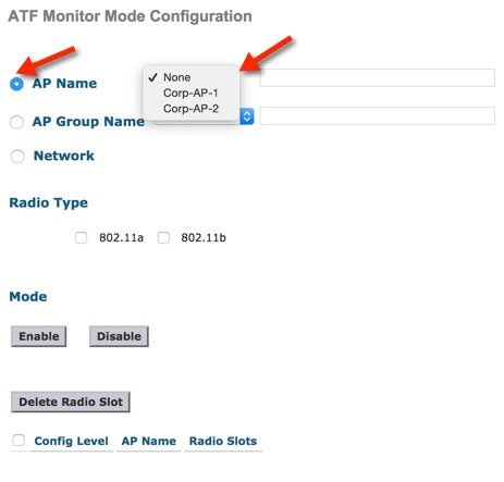 |
|
Step 2 |
Choose the Radio Type by checking the 802.11a or 802.11b or both radio boxes and click Enable under the Mode option. 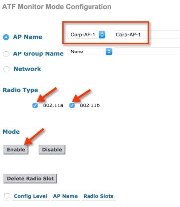 Once
configuration is done it displays the config level, AP name and radio slots (Slot 0 is 802.11b Radio and
Slot 1 is 802.11a Radio) on which monitoring is enabled.
|
Per AP Group Monitoring Configuration
For per AP group monitoring configuration, perform the following steps:
Procedure
|
Step 1 |
Click AP Group Name and from the drop down menu choose the AP Group. 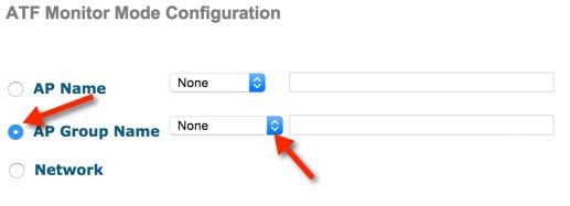 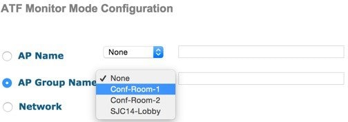 |
|
Step 2 |
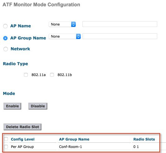
Choose the Radio Type by checking the 802.11a or 802.11b or both radio boxes and click Enable under the Mode option. 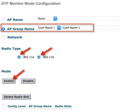 Once
configuration is done it displays the config level, AP name and radio slots (Slot 0 is 802.11b Radio and
Slot 1 is 802.11a Radio) on which monitoring is enabled.
 |
ATF Network Monitoring Configuration
To monitor Air Time on the network, perform the following steps:
Procedure
|
Step 1 |
Click Network and this displays the monitor is disabled on the network. 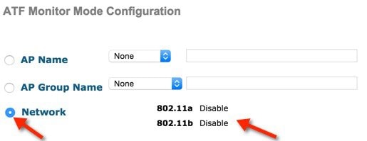 |
|
Step 2 |
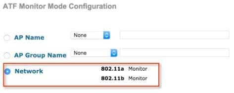
Choose the Radio Type by checking the 802.11a or 802.11b or both radio boxes then click Enable under the Mode option 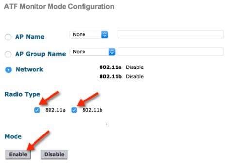 When
ATF network monitoring is configured user can see that Radio status change to
Monitor from Disable state.
 |
Monitoring ATF Statistics
Procedure
|
Step 1 |
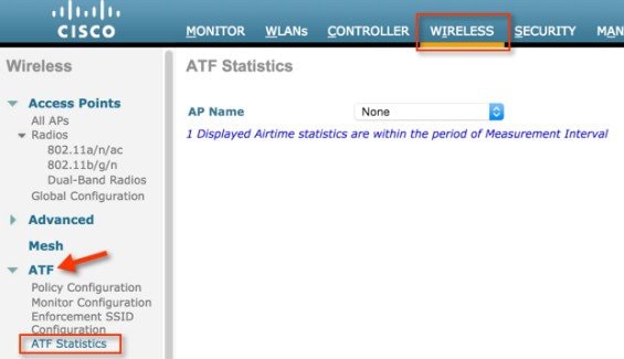
To view the ATF statistics from WLC main menu go to WIRELESS > ATF > ATF Statistics.
|
||
|
Step 2 |
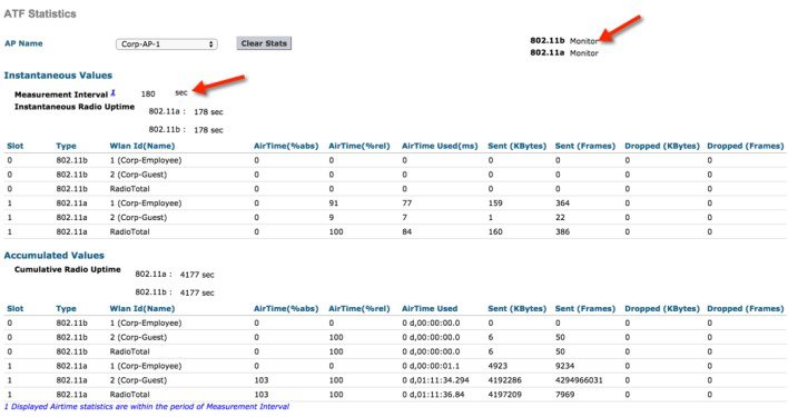
Choose the AP from the AP Name dropdown list. 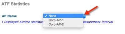 The ATF
statistics will show under two following values:
The Instantaneous values reflect the ATF stats through the measurement interval and Instantaneous Radio uptime. By default the measurement interval is set to180 sec. This is configurable in the range 0 to 65535 on the AP. User can view the atf stats per WLAN for both 802.11a and 802.11b radios which shows the percentage of AirTime (%abs), percentage of Realtive AirTime(%rel), AirTime used value in miliseconds (ms)
The
Accumulative Values are the instantaneous ATF statistics which were accumulated
over the measurement interval.
 |
Disabling ATF Monitor Mode
Procedure
|
Step 1 |
To disable the ATF monitoring navigate to WIRELESS > ATF > Monitor Configuration. |
|
Step 2 |
Choose the options AP Name, AP group and Network from the drop down menu, whichever the user has previously enabled. Select the Radio Type the user want to disable and click Disable. 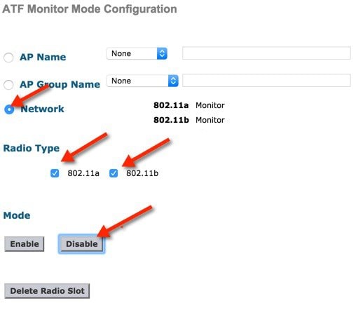 |
|
Step 3 |
Click OK on the pop up conformation to disable the ATF. 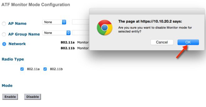 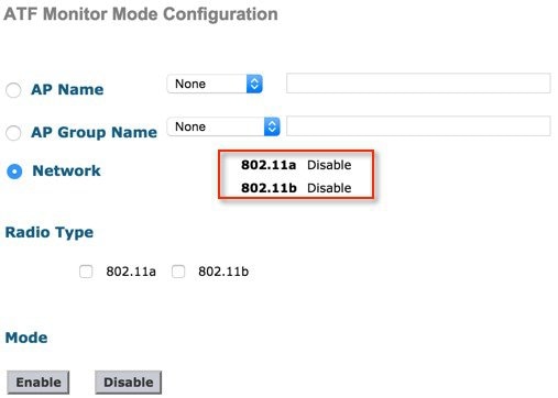 |
ATF Enforce-Policy Mode
The Enforcement of Air Time is based on the configured Policy. The ATF Policy/Policies are set by user according to the network requirements.
Air-Time can be Enforced on following parameters:
-
WLAN and on all APs connected within a WLC’s network
-
Per AP group
-
On an individual AP
Strict Enforcement per WLAN—Air-Time used by the WLANs on a Radio will be strictly enforced up to the configured limits in the Policies
Optimal Enforcement per WLAN—Share unused air-time from other SSIDs
Steps to Configure ATF
Create Policy
To configure ATF first the user need to create or configure ATF policy.
Procedure
|
Step 1 |
Navigate WIRELESS > ATF > Policy Configuration. |
|
Step 2 |
The Default policy is 10 and the user has to assign weight from 5 to 100. 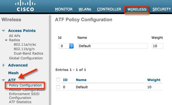 |
|
Step 3 |
To create user own policy select the policy Id from the drop down menu and assign a name and weight. Here Weight is the percentage of Air Time which user want to assign to a policy. |
|
Step 4 |
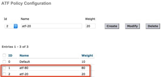
Click Create. 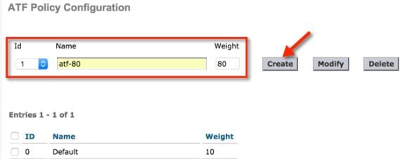 In the
example we have created multiple policies with the name
atf-80
and
atf-20
with the Weights 80 and 20 respectively.
 |
Policy Enforcement on SSID
 Note |
First disable the WLANs on which you want to enable policy enforcement. |
Once the policy is configured user can apply the policy to a particular WLAN or on all WLANs per AP group or on an individual AP.
Procedure
|
Step 1 |
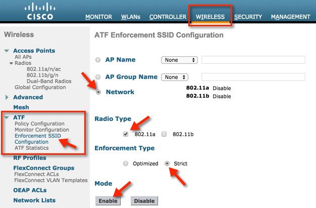
Naviage to the WLC main menu WIRELESS > ATF > Enforcement SSID Configuration. 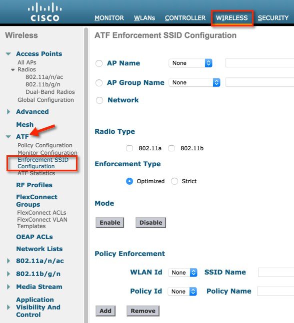 |
|
Step 2 |
To configure it on the network Select the parameters Radio Type, Enforcement Type (can select either Optimized or Strict; by default Optimized is selected. |
|
Step 3 |
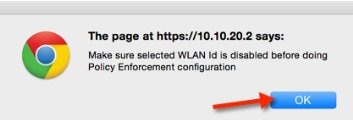
Click Enable under the Mode. 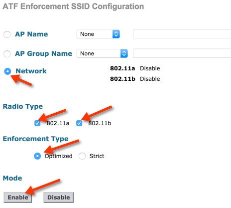 When
applied, the webpage gives the popup warning to disable the WLAN id before
configuring policy enforcement. Click
Ok, if the
WLAN is disabled the enforcement gets applied.
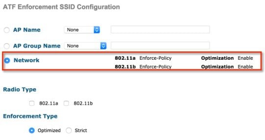
 The policy
Enforcement shows on Radios and also the Optimization shows Enabled.
 |
|
Step 4 |
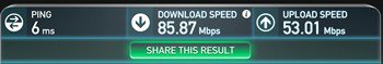
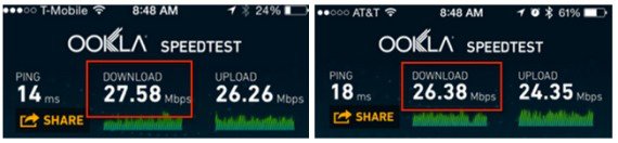
To enable strict enforcement policy then select Strict option under Enforcement type. Strict option does not allow sharing of its weighted ratio slot with other WLANs (SSIDs). 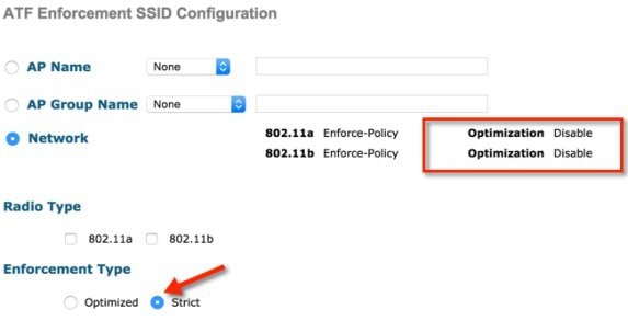 When the ATF configuration is done, then Enable the WLANs on which ATF was applied. Once the clients are associated to these WLANs user can view the ATF statistics under the ATF statistics page as previously shown in Monitoring ATF Statistics section. The user can also run a speed test to verify the ATF by configuring two WLANs with different ATF policies. In the
example we have configured two ATF policies, one with weight 80 and other with
weight 20.
|
Air Time Fairness–Client Fair Sharing (ATF—Phase 2)
Feature Description
ATF Client Fair Sharing/per client entitlement is introduced in 8.2 release. Client fair share ensures the clients within a SSID/WLAN are treated equally based on their utilization of the radio bandwidth.
Benefit
Currently, as part of 8.1 MR2 and MR3 release, SSID based Airtime entitlement is accomplished. However, with SSID based Airtime Fairness, there is no guarantee for the clients within the SSID to be treated equally based on their utilization of the radio bandwidth. There is a potential risk where one or few clients shall end up utilizing the complete airtime allocated for a SSID/WLAN by ruining the opportunity of Wi-Fi experience for rest of the clients within the same SSID.
ATF Phase 1 (Without Client Fair Sharing)
To overcome this problem, in 8.2 release each ATF policy have a new option to turn on or off client fair sharing among clients associated to a policy. This option can be executed while creating, modifying the policy in the Wireless LAN Controller. Customer can use this option or feature to provide fair sharing of Airtime between clients associated to a SSID. As shown below all the clients associated to SSID gets equal air time.
ATF Phase 2 (With Client Fair Sharing)
ATF Configuration Overview
Procedure
|
Step 1 |
First configure WLANs on the controller. |
|
Step 2 |
Configure ATF Policies and enable ATF assign those policies to the WLANs. |
|
Step 3 |
Connect clients to the ATF enabled WLAN and use media stream applications such as YouTube or https://www.speedtest.net/ and observe throughput performance with different ATF policies and weights for downstream data traffic. |
Configuration for ATF Phase 2
Procedure
|
Create WLANs on the controller in our setup we created two WLANs PODX-atf20 and PODX-atf80. 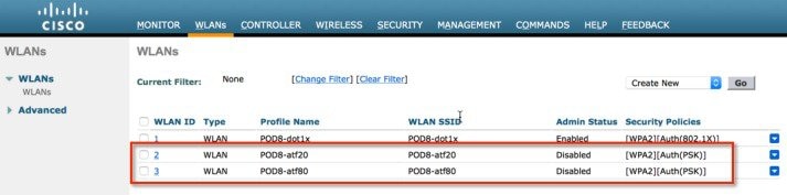 |
Creating ATF Client Fair Sharing Policies
Procedure
|
Step 1 |
On the Controller GUI under WIRELESS > ATF click Policy Configuration and configure Id Name. Id Name can be any intuitive name, in our example we are configuring the name atf20 and atf80) for weights of 20 and 80 respectively. |
||
|
Step 2 |
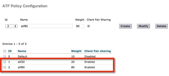
Check the Client Fair Sharing box and hit Create to Create two policies. User can assign there own ATF policy weights in example below we are using 20 and 80.
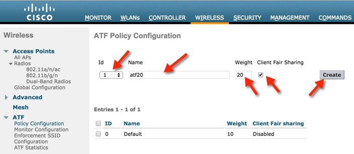 The configuration sets the policy, which can be applied per radio. The two Policy IDs and Weights define policy Id 1 with weight 20 and the second policy Id 2 with weight 80 and Client Fair Sharing shows Enabled.
|
Configure and Enable ATF policy on the Network and per specific Radio Type
Procedure
|
Step 1 |
Navigate Wireless > ATF > Enforce SSID configuration. |
||
|
Step 2 |
Select Network and select Radio Type as 802.11a/b. |
||
|
Step 3 |
Choose the policy Enforcement Type asOptimized or Strict. Apply policy as Strict in the setup.
 The policy displays that it has been enabled on 5GHz radio and is not Optimized but in Strict mode. 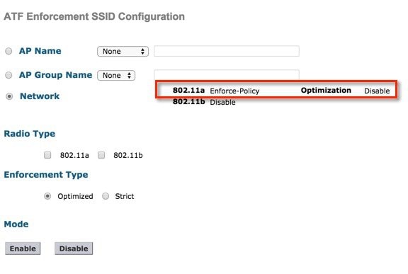 |
Apply ATF Policy on WLANs
Procedure
|
Step 1 |
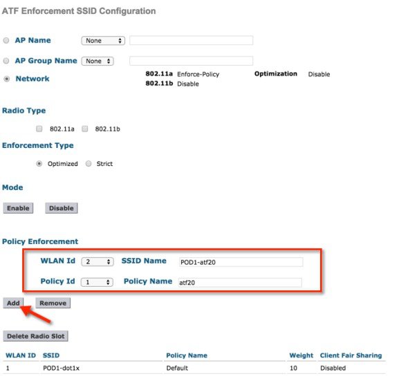
Navigate Wireless > ATF > Policy Enforcement. |
|
Step 2 |
Select the WLAN Id and Policy Id. |
|
Step 3 |
Click Apply. We use ATF policy (atf20) for one WLAN and policy (atf80) for another WLAN as shown.
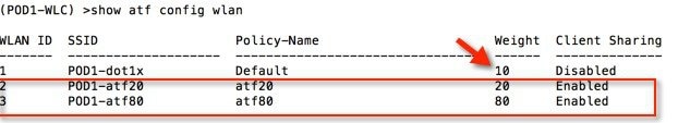
 Once the policies are created and applied to the WLANs, users can check this by running show atf config wlan command from WLC CLI and also on the GUI. You can see from the output that ATF policy configured WLANs are set with configured weights of 20 and 80 and the WLAN on which we did not apply the policy is set to default weight of 10. Also check that Client Fair Sharing shows Enabled for ATF polices we created. Here is an example is from CLI to confirm the policies have been applied
 |
Enable WLANs in Disabled State
Procedure
|
Step 1 |
Navigate toATF > Enforcement SSID Configuration settings. 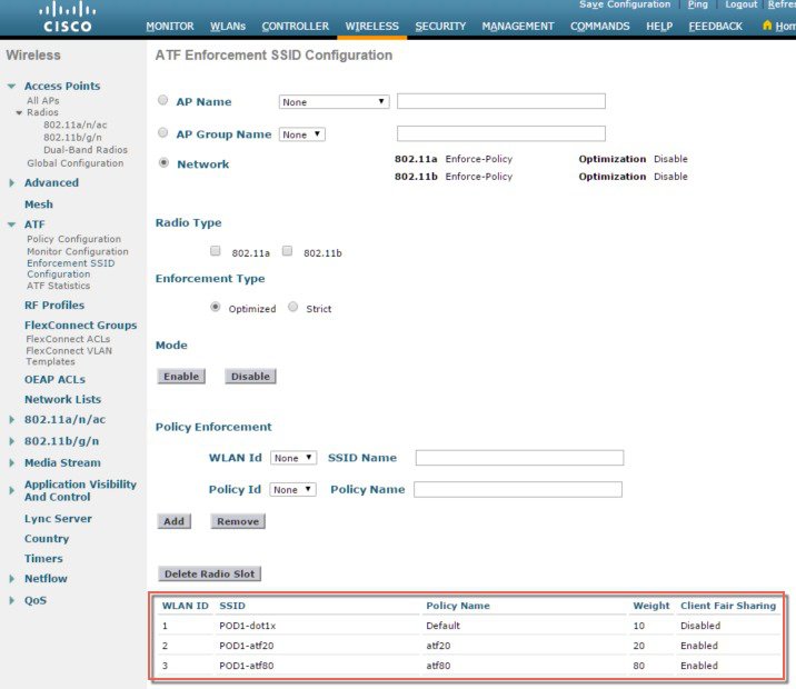 |
|
Step 2 |
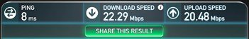
Connect two wireless clients to SSID that is configured with policy 80 and observe the effect of the ATF on this WLAN. |
|
Step 3 |
Run https://www.speedtest.net/ simultaneously on the clients at the same time. The test results might vary due to the clients capability, interference and other factors.
 |
|
Step 4 |
Connect a wireless Client to SSID configured with ATF policy and observe the effects of the ATF on that WLAN. You should see speedtest performance on the download the test results might vary due to the clients capability, interference and other factors. |
Client ATF Statistics
Procedure
|
Step 1 |
Navigate WIRELESS > ATF > ATF Statistics and then select the AP Name from the drop down menu to which the clients are connected. 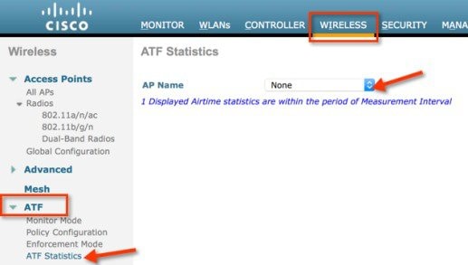 ATF
Statistics page appears where user can view all the ATF enabled WLAN
statistics.
|
|
Step 2 |
To have a granular view of ATF client fair sharing statistics click WLAN id which has client fair sharing enabled as shown. 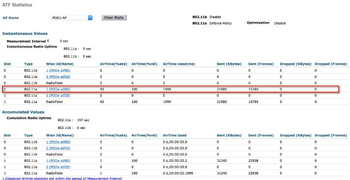 |
|
Step 3 |
Clicking the client MAC address, users can view the WLAN ATF stats as well as client ATF statistics for all the clients associated with that particular WLAN. 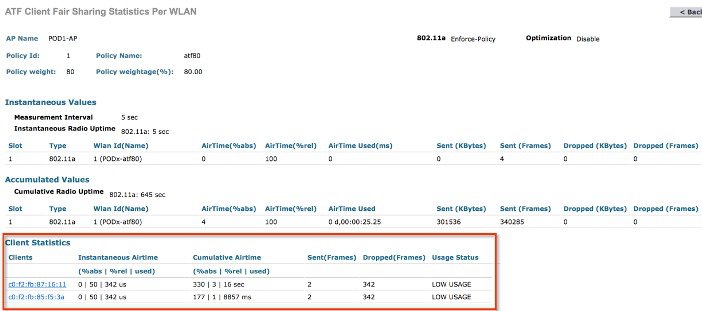 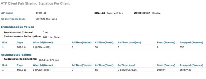 |
ATF Client Statistics from WLC CLI
From CLI user can also run the following command to see the atf statistics per client on the WLC
(WLC)> show atf statistics client <MAC addr>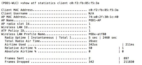
Client Statistics on AP
If required user can login to AP CLI to see that Clients stats as well by running the following command
AP# show controller dot11Radio <0/1> atf
AP # show controller d0/d1 atf cfs client
 Feedback