Cisco Catalyst IW9167E Heavy Duty Access Point Configuration Guide, Cisco IOS XE Cupertino 17.9.x
Overview of Supported Access Point Modes
The Cisco Catalyst IW9167E Heavy Duty Access Point provides reliable wireless connectivity for mission-critical applications in a state-of-the art platform. It can operate as Cisco Catalyst Wi-Fi (CAPWAP) mode or Cisco Ultra-Reliable Wireless Backhaul (Cisco URWB) mode. The IW9167EH access point has the flexibility to change the operating mode from Wi-Fi to Cisco URWB, and vice versa.
This document covers configuration of CAPWAP mode specific to the IW9167EH access points. The access points can operate in the following modes:
-
Local
-
Flexconnect
-
Bridge
-
Flexconnect + Bridge
-
Sniffer
-
Monitor
IW9167EH is supported on Cisco Catalyst 9800 Series Wireless Controllers from IOS XE 17.9.3 Software Release. For more information about the configuration on 9800 WLC, see Cisco Catalyst 9800 Series Wireless Controller Software Configuration Guide, Cisco IOS XE Cupertino 17.9.x.
To view all support information for the Cisco Catalyst IW9167E Heavy Duty Access Point, see https://www.cisco.com/c/en/us/support/wireless/catalyst-iw9167-series/series.html.
In addition to the documentation available on the support page, you will need to refer to the following guides:
-
For information about IW9167EH hardware, see Cisco Catalyst IW9167E Heavy Duty Access Point Hardware Installation Guide.
-
A full listing of the AP's features and specifications is provided in Cisco Catalyst IW9167E Heavy Duty Access Point Data Sheet.
-
For information about Cisco URWB mode configuration, see the relevant documents at:
https://www.cisco.com/c/en/us/support/wireless/catalyst-iw9167-series/series.html.
-
For more information about Cisco IOS XE, see the relevant documents at:
http://www.cisco.com/c/en/us/products/ios-nx-os-software/ios-xe/index.html
Determine Image on IW9167EH
Software images are stored under different folders on the same partition on IW9167EH.

You need to choose the image to boot up with according to the mode your AP is runnning: CAPWAP, or Cisco URWB.
|
IW9167EH Mode |
Software Image |
||
|---|---|---|---|
|
CAPWAP |
ap1g6a-k9w8-xxx.tar |
||
|
Cisco URWB
|
ap1g6j-k9c1-xxx.tar |
To determine the image that your IW9167EH is running, use the show version command.
-
If the show version output displays Cisco AP Software, (ap1g6a) as shown in the following example, it means that AP is running the CAPWAP image ap1g6a-k9w8-xxx.tar, which supports the CAPWAP mode.
Cisco AP Software, (ap1g6a), C9167, RELEASE SOFTWARE Technical Support: http://www.cisco.com/techsupport Copyright (c) 1986-2022 by Cisco Systems, Inc. Compiled Fri Jul 29 01:56:00 PDT 2022 ROM: Bootstrap program is U-Boot boot loader BOOTLDR: U-Boot boot loader Version 2022010100 APFC58.9A16.E648 uptime is 0 days, 1 hours, 03 minutes Last reload time : Mon Sep 19 02:23:13 UTC 2022 Last reload reason : Image Upgrade cisco IW9167EH-B ARMv8 Processor rev 4 (v8l) with 1757076/1006864K bytes of memory. -
If the show version output displays Cisco AP Software (ap1g6j) as shown in the following example, it means that AP is running ap1g6j-k9c1-xxx.tar image, which supports the Cisco URWB mode.
Cisco AP Software, (ap1g6j), C9167, RELEASE SOFTWARE
Technical Support: http://www.cisco.com/techsupport
Copyright (c) 1986-2022 by Cisco Systems, Inc.
Compiled Thu Aug 18 01:01:29 PDT 2022

ROM: Bootstrap program is U-Boot boot loader
BOOTLDR: U-Boot boot loader Version 2022010100

APFC58.9A16.E464 uptime is 1 days, 3 hours, 58 minutes
Last reload time   : Wed Sep 7 11:17:00 UTC 2022
Last reload reason : reload command

cisco IW9167EH-B ARMv8 Processor rev 4 (v8l) with 1759128/1091316K bytes of memory.
Configuring AP to Boot up with Different Image Options
To configure the access point to boot up with CAPWAP or URWB mode, follow these steps:
 Note |
Switching between different modes performs full factory reset. Any configuration and data will be removed completely. |
Procedure
|
Step 1 |
enable Enables privileged EXEC mode. Enter your password if prompted. |
|
Step 2 |
configure boot mode {capwap |urwb } Configures AP to CAPWAP or URWB mode. AP will reboot with specified mode. |
Configuring Indoor Deployment for -E Domain
IW9167EH supports indoor deployment for -E domain.
By default, indoor deployment is disabled, and the 5G radio supports channels 100, 104, 108, 112, 116, 120, 124, 128, 132, 136, 140. After factory reset, indoor deployment configuration is reset to default, which is disabled.
You can check AP mode by using the show ap name <ap-name> config general | section Indoor command. In the command output, "Enabled" means AP is in indoor mode, and "Disabled" means AP is in outdoor mode, as shown in the following example.
#show ap name APFC58.9A15.C9A4 config general | inc Indoor
    AP Indoor Mode                                  : Disabled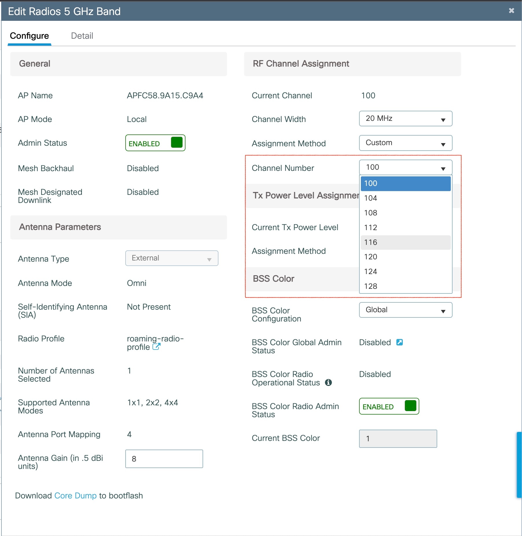
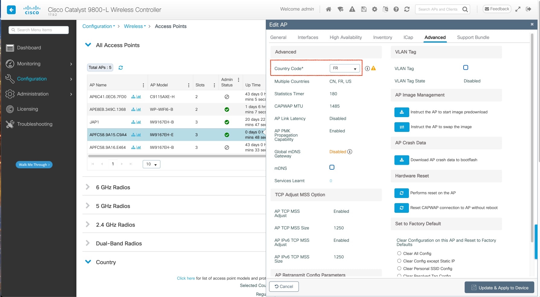
To configure the AP to indoor mode, use the ap name <ap-name > indoor command from wireless LAN controller. This command triggers an AP rebooting. After AP registers to the wireless LAN controller after rebooting, you need to assign corresponding country code to the AP. When indoor deployment is enabled, 5G radio supports channels 36, 40, 44, 48, 52, 56, 60, 64, 100, 104, 108, 112, 116, 120, 124, 128, 132, 136, 140.
Note |
To disable indoor deployment, use the ap name <ap-name > no indoor command. |

Note |
Channel list extends from U-NII-2c to U-NII-1, U-NII-2a, U-NII-2c (channel 144 is excluded). |
802.11ax 1600ns and 3200ns Guard Interval Support
802.11ac has two Guard Interval (GI) options – long GI (800ns) and short GI (400ns). 802.11ax introduces new guard interval options. It has three types of GI – 800ns, 1600ns, and 3200ns. Longer guard intervals provide improved performance in environments with multi-path and delay spread. It improves link reliability for longer-range outdoor deployments and helps to prevent inter-symbol interference in outdoor environments and therefore improve coverage and performance.
The following table compares 802.11ax to the previous two standards.
|
Capabilities |
802.11n |
802.11ac |
802.11ax |
|---|---|---|---|
|
Physical Layer (PHY) |
High Throughput (HT) |
Very High Throughput (VHT) |
High-Efficiency (HE) |
|
Guard Interval |
800/400 ns |
800/400 ns |
800/1600/3200 ns |
Configuring 802.11ax Long Guard Interval
HE mode guard intervals should be configured in RF profiles.
Procedure
|
Step 1 |
Enters global configuration mode. Example: |
||
|
Step 2 |
Configures RF profile and enters RF profile configuration mode Example: |
||
|
Step 3 |
Configures guard interval for the RF profile. Example:
|
||
|
Step 4 |
Exit global configuration mode. end Example: |
Use the following command to verify the configuration on wireless controller:
#show ap rf-profile name Demo-24G-RF-profile detail | inc Guard
Guard Interval        : 1600ns
#show ap rf-profile name Demo-5G-RF-profile detail | inc Guard
Guard Interval        : 3200ns
Example
1. Define GI in RF profile
ap dot11 24ghz rf-profile Demo-24G-RF-profile
shutdown
guard-interval GUARD_INTERVAL_1600NS
no shutdown
ap dot11 5ghz rf-profile Demo-5G-RF-profile
shutdown
guard-interval GUARD_INTERVAL_3200NS
no shutdown
2. Associate RF profile to RF tag
wireless tag rf Demo-Guard-Interval-RF-tag
24ghz-rf-policy Demo-24G-RF-profile
5ghz-rf-policy Demo-5G-RF-profile
3. Associate RF tag to AP
ap fc58.9a15.c83c
rf-tag Demo-Guard-Interval-RF-tag
RAP Ethernet Daisy Chain
The RAP Ethernet Daisy Chain feature enhances the existing Ethernet bridging functionality by configuring strict wired uplink on each access point. It forces the bridge AP to stick to the Ethernet link, and block the selecting of wireless link for uplink backhaul. Even the Ethernet link failure happens, the access point will never select a parent over wireless backhaul.
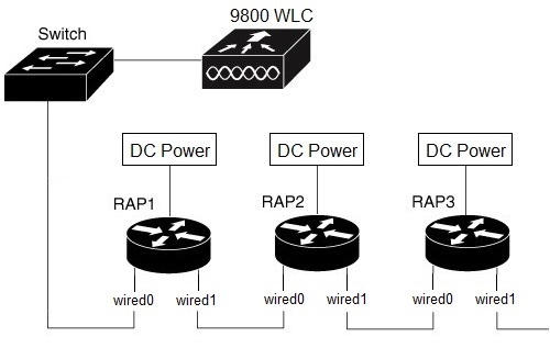
The following figure shows an example of RAP Ethernet Daisy Chain topology. Standalone DC power source is provided to each RAP.
|
Panel Label |
SW Interface |
|---|---|
|
mGig POE-IN port |
wired 0 |
|
SFP |
wired 1 |
Note |
The supported SFP module for this feature is the 1000BASE-T rugged SFP (Cisco PID: GLC-T-RGD). |
Follow these guidelines when you configure this feature:
-
All APs in daisy chain is operating in mesh bridge mode or Flex+Bridge mode with Root AP role. The PoE-IN (wired0) and SFP (wired1) port can be used as uplink port and the PoE-IN (wired0) port has the higher priority than SFP (wired1).
-
VLAN transparency should be disabled on all daisy-chained RAPs.
-
To enable VLAN support on each root AP:
-
For bridge mode APs, use the ap name name-of-rap mesh vlan-trunking [native] vlan-id command to configure a trunk VLAN on the corresponding RAP.
-
For Flex+Bridge APs, you must configure the native VLAN ID under the corresponding flex profile.
-
-
Strict wired uplink should be enabled to prevent RAP in daisy chain from switching to wireless backhaul when the wired uplink path fails, so that the RAP can recover quickly when the uplink wired path is recovered.
RAP Ethernet Daisy Chain Configuration
This section provides procedures of the RAP Ethernet daisy chain configuration.
Configuring Ethernet Bridging (CLI)
The Ethernet port on the MAPs are disabled by default. It can be enabled only by configuring Ethernet bridging on the Root AP and the other respective MAPs. Follow these steps to enable Ethernet bridging on the AP.
Procedure
|
Step 1 |
Enters global configuration mode. |
|
Step 2 |
Creates a mesh profile. Example: |
|
Step 3 |
ethernet-bridging Example:Connects remote wired networks to each other. |
|
Step 4 |
Disables VLAN transparency to ensure that the bridge is VLAN aware. Example: |
|
Step 5 |
Exit global configuration mode. end Example: |
Example
Use the following command to verify the configuration:
#show wireless profile mesh detailed rap-eth-daisy

Mesh Profile Name           : rap-eth-daisy
--------------------------------------
Description                 :
Bridge Group Name           : unconfigured
Strict match BGN            : DISABLED
Amsdu                       : ENABLED
Background Scan             : DISABLED
Channel Change Notification : DISABLED
Backhaul client access      : DISABLED
Ethernet Bridging           : ENABLED
Ethernet Vlan Transparent   : DISABLED
Daisy Chain SP Redundancy   : DISABLED
Full Sector DFS             : ENABLED
Configuring Ethernet Bridging (GUI)
Follow these steps to configure Ethernet Bridging from wireless controller GUI:
Procedure
|
Step 1 |
Choose Configuration > Wireless > Mesh > Profiles |
|
Step 2 |
Click Add. |
|
Step 3 |
In General tab, enter the Name of the mesh profile. |
|
Step 4 |
In Advanced tab, uncheck the VLAN Transparent check box to disable VLAN transparency. |
|
Step 5 |
In Advanced tab, check the Ethernet Bridging check box. |
|
Step 6 |
Click Apply to Device. 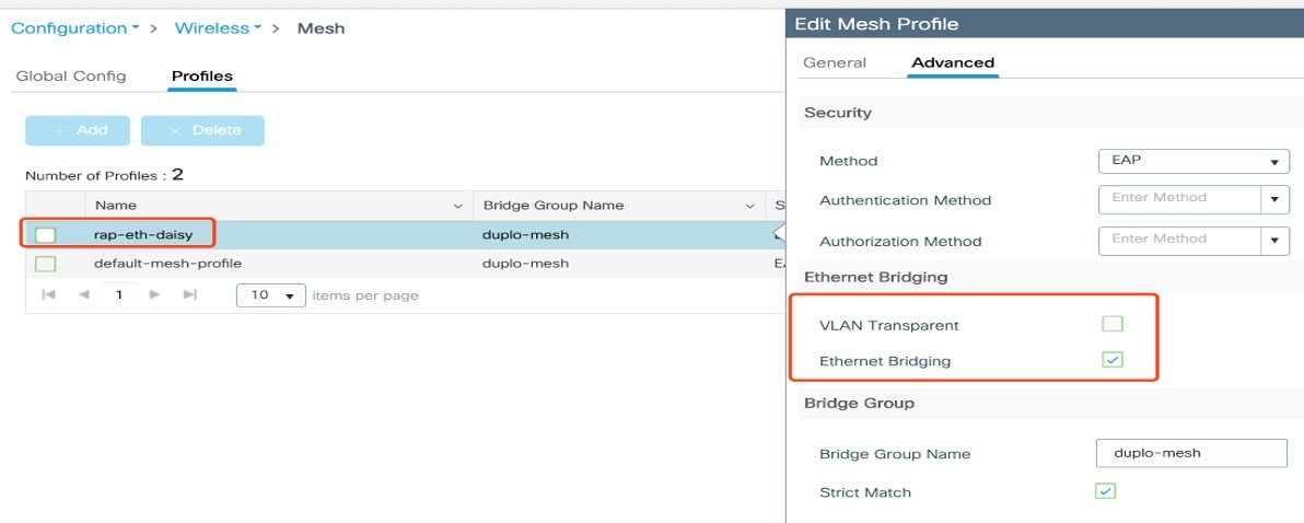
|
Configuring Strict Wired Uplink
Follow these steps to configure persistent SSID broadcast and ensures strict wired uplink. RAP will not switch to wireless backhaul when you configure this command.
Note |
You can only use CLI to configure and show status of ssid-broadcast-persist. It's not supported on the GUI. |
Procedure
| Command or Action | Purpose | |
|---|---|---|
|
Step 1 |
configure terminal Example: |
Enters global configuration mode. |
|
Step 2 |
ap profile profile-name Example: |
Specifies an AP profile. |
|
Step 3 |
[no ] ssid broadcast persistent Example: |
Enables persistent SSID broadcast and ensures strict wired uplink. Use the no form of the command to disable persistent SSID broadcast. |
|
Step 4 |
end Example: |
Returns to privileged EXEC mode. |
Example
Use the following command to verify the configuration:
#show ap profile name rap-ssid-join-profile detailed | in SSID
Persistent SSID Broadcast             : ENABLED
Configuring Ethernet Port (CLI)
RAP Ethernet secondary port supports Access mode and Trunk mode. Follow these steps to configure Ethernet port mode.
-
Use the following command to configure access mode.
#ap name ap-name mesh ethernet 1 mode access Vlan-ID
-
Use the following commands to configure trunk mode. VLAN support must be enabled in advance, and VLAN transparent should be disabled in your mesh profile.
-
Configure a trunk VLAN on the corresponding RAP.
#ap name ap-name mesh vlan-trunking native Vlan-ID
-
Configure the native VLAN for the trunk port.
#ap name ap-name mesh ethernet 1 mode trunk vlan native Vlan-ID
-
Configure the allowed VLANs for the trunk port. Permits VLAN filtering on an ethernet port of any Mesh or Root Access Point. Active only when VLAN transparency is disabled in the mesh profile.
#ap name ap-name mesh ethernet 1 mode trunk allowed Vlan-ID
-
Configuring Ethernet Port (GUI)
Follow these steps to configure Ethernet port from wireless controller GUI:
Procedure
|
Step 1 |
Choose Configuration > Wireless > Access Points. The All Access Points section, which lists all the configured APs in the network, is displayed with their corresponding details. |
|
Step 2 |
Click the configured mesh AP. The Edit AP window is displayed. |
|
Step 3 |
Choose the Mesh tab. |
|
Step 4 |
In the Ethernet Port Configuration section, from the Port drop-down list, choose the port to configure. |
|
Step 5 |
From the Mode drop-down list, choose access mode or trunk mode. |
|
Step 6 |
In the Native VLAN ID field, enter the native VLAN for the trunk port. |
|
Step 7 |
Click Update and Apply to Device. 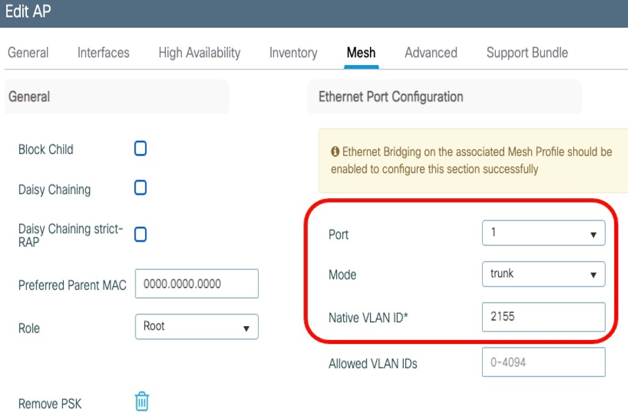
|
 Feedback