Parallel Redundancy Protocol Over Wireless Deployment Guide
This document provides details about configuring Parallel Redundancy Protocol (PRP) over wireless on the Cisco IW3702 access points.
 Note |
The documentation set for this product strives to use bias-free language. For purposes of this documentation set, bias-free is defined as language that does not imply discrimination based on age, disability, gender, racial identity, ethnic identity, sexual orientation, socioeconomic status, and intersectionality. Exceptions may be present in the documentation due to language that is hardcoded in the user interfaces of the product software, language used based on RFP documentation, or language that is used by a referenced third-party product. |
Information About Parallel Redundancy Protocol (PRP) over Wireless
Parallel Redundancy Protocol (PRP) is defined in the International Standard IEC 62439-3. PRP is designed to provide hitless redundancy (zero recovery time after failures) in Ethernet networks.
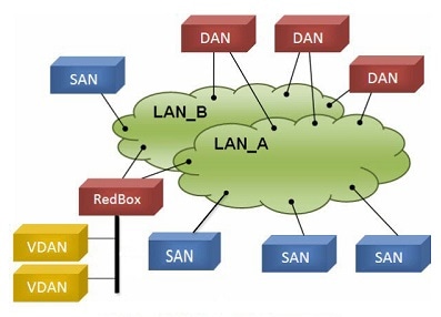
PRP allows a data communication network to prevent data transmission failures by providing two alternate paths for the traffic to reach its destination. Two Ethernet networks (LANs) with similar topology are separated.
A device that requires protection for data across the network connects to the two independent networks (LAN-A and LAN-B) is called a Dual Attached Node implementing PRP (DANP). A DANP source sends two frames simultaneously on both LANs. A DANP destination receives both frames and discards the duplicating. If one LAN fails, a DANP destination can still receive a frame from the other LAN.
Nonredundant endpoints in the network that attach only to either LAN-A or LAN-B are known as Singly Attached Nodes (SANs). A Redundancy Box (RedBox) is used when a single interface node must be attached to both networks. Such a node can communicate with all other nodes.
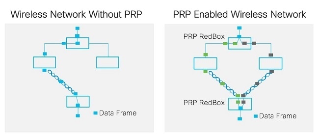
The PRP functionality is available on wireless since Cisco Wireless Controller Release 8.4. The feature is designed to bridge wired client traffic (behind the WGB) using dual radio links to provide reliable wireless transmission. As shown in the following figure, the typical wireless data transmission goes over a single radio path and is susceptible to RF interference and packet loss during handoff. The PRP over Wireless feature creates a redundant radio path for data transmission and enables consistent and reliable data connectivity over the wireless network. It allows the distribution of traffic over two parallel wireless connections to achieve the highest level of resilience and reduction in delay variation.
The PRP over Wireless feature is supported on IW3702 WGB with two redundancy options. Wired client traffic is duplicated and transmitted on dual radio links either by two WGBs (dual WGB, dual radio), or by a single WGB with dual radio links (single WGB, dual radio). Each redundancy option is discussed in detail in the following sections with sample configurations provided.
Prerequisites and Components Used
The PRP over wireless feature is supported for the following software releases, platforms, and AP Modes.
-
Dual WGB dual radio redundancy option – Wireless Controller Software Release 8.4
-
Single WGB dual radio redundancy option – Wireless Controller Software Release 8.5
-
APs on the infrastructure side – FlexConnect mode (central authentication, local switching). The following IOS-based platforms are supported: IW3702, 2700, 3700, and 1570 series.
-
WGB on the mobile client side – IW3702
The configuration example that is given in this document involves the following components:
-
Wireless LAN Controller (WLC) – Release 8.5.120.0
-
Infrastructure APs – IW3702 APs in FlexConnect mode (central authentication, local switching)
-
WGB – IW3702 AP running autonomous image of Release 15.3(3)JF
-
PRP switch – IE 4000 with image version ie4000-universal-mz.152-4.EA5
-
Aggregate switch with Dot1q tunneling function – Catalyst 3750
Dual WGB Dual Radio PRP Redundancy Option
These sections contain configurations of the infrastructure side and mobile client side for dual WGB dual radio PRP redundancy.
Example Network Topology
The following figure shows an example of dual WGB dual radio PRP redundancy topology.
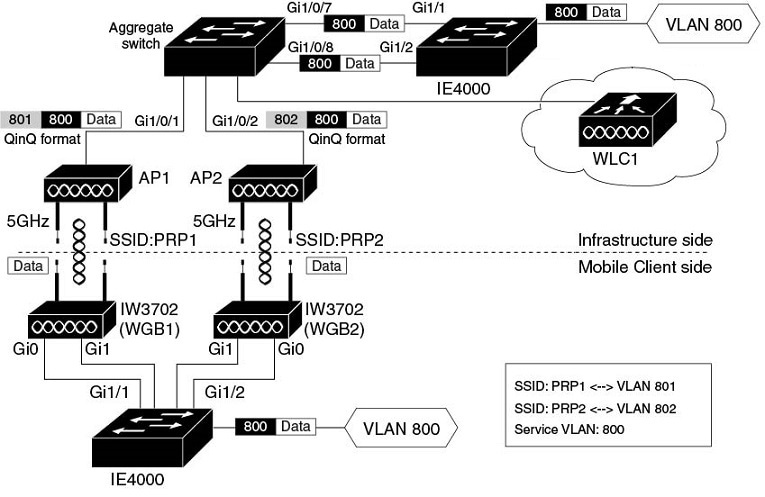
In this topology, the redundant path is provided by two 5GHz radios on two WGBs. The two PRP switches (in this example, the Cisco IE4000) work as RedBox (redundancy box) on both the mobile client side and network infrastructure side, performing packet duplication and duplication discard.
Detailed functions of each network component are described as following:
Infrastructure side:
-
The PRP capable switch (in this example, the Cisco IE4000) on the infrastructure side serves as the RedBox, performing packet duplication and duplication discard.
-
APs on the infrastructure side transmit and receive redundant data traffic over different SSIDs (in this example, PRP1 and PRP2), and tag the data with different VLANs (QinQ Tunnel encapsulation or decapsulation).
-
The traffic between aggregate switch and APs is in QinQ format to identify the path where they come from. The QinQ function is enabled on the aggregate switch Ethernet interfaces (Gi1/0/7 and Gi1/0/8), which connect to the IE switch PRP ports. These two interfaces perform QinQ Tunnel encapsulation for downstream traffic and decapsulation for upstream traffic, so that the duplicated traffic can be carried over different VLANs.
Mobile client side:
-
The Gig port 0 (PoE IN) of each IW3702 is connected to the two PRP ports of the PRP switch. Since the IE4000 PRP port is not a PoE port, IW3702 should connect to a power injector.
-
PRP-capable switch IE4000 is used to perform packet duplication and duplication discard function for the client VLAN traffic (VLAN 800).
-
Each IW3702 works as a WGB, which associates to different SSIDs (in this example, PRP1 and PRP2) and locates in different VLANs (in this example, VLAN 801 and VLAN 802). The redundant wireless paths are provided for wired clients behind the WGB by two 5GHz radios on two WGBs.
Roaming Coordination:
-
Gig port 1 (PoE OUT) of the two IW3702s can be connected through the IE switch Ethernet interface to provide roaming coordination function, which prevents both WGBs from roaming at the same time.
Note
When powered by the PoE IN port with 802.3at power input, the IW3072 Gig port 1 can still forward traffic. But the PoE OUT functionality is not supported.
Infrastructure Side Configuration
This section contains the following infrastructure side configurations.
Wireless LAN Controller Configuration
This section contains the following Wireless LAN Controller configurations.
WLAN Creation
For the PRP over wireless to function, two WLANs (SSIDs) in two different interfaces (VLANs) are required to carry redundant wireless traffic. Configure the WLANs across all the infrastructure side APs.
Procedure
| Step 1 |
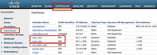
Create dynamic interfaces. For the PRP and QinQ to work under Flexconnect and local switch mode, you should configure the following dynamic interfaces:
 |
||
| Step 2 |
Create WLAN with SSID (PRP1/PRP2). 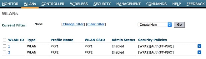 |
||
| Step 3 |
The PRP over wireless feature works only in Flexconnect mode. Enable FlexConnect Local Switching mode on the WLANs that have been created. 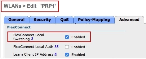 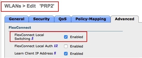 |
||
| Step 4 |
Connect the APs to the infrastructure and make them join the WLC in Flexconnect mode. 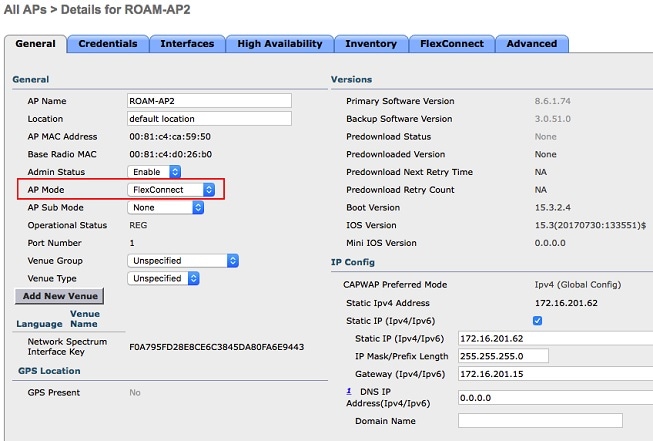 |
||
| Step 5 |
Enable VLAN mappings on all APs and make sure that WLANs created for PRP are included for the VLANs. 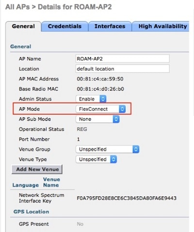 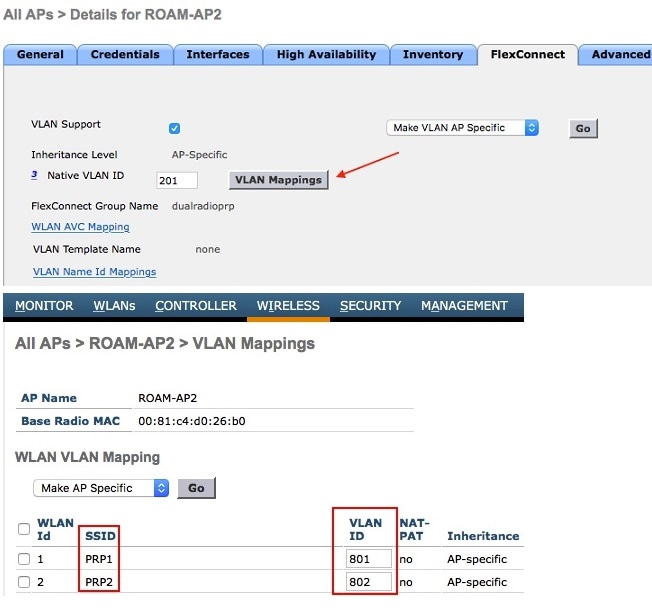
|
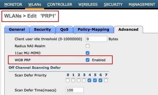
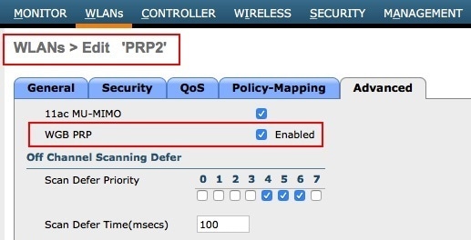
Enabling PRP Under WLAN
Make sure to enable the PRP feature only for the WLANs that require PRP functionality. In this example, PRP feature should be enabled for WLAN PRP1 and WLAN PRP2.
Configuring WGB Multiple Client VLAN
To enable WGB client multiple VLAN support, both WLC and WGB need to be configured.
On WLC, navigate to the Controller > General tab, and choose Enable for WGB VL AN client.
On WGB, use the following command to enable WGB VLAN tagging:
WGB(config)#workgroup-bridge unified-vlan-client
WGB(config)#workgroup-bridge unified-vlan-client broadcast-tagging
Note |
When you have multiple VLAN configurations on WGB, you need to configure the encryption cipher mode and keys for a particular VLAN, for example, encryption vlan 801 mode ciphers aes-ccm. Then, you need to configure the encryption cipher mode globally on the multicast/broadcast interface by entering the following command: encryption mode ciphers aes-ccm. |
PRP Switch Configuration
Several Cisco Industrial Ethernet switches support PRP feature.
PRP channel or channel group is a logical interface that aggregates two Gigabit Ethernet interfaces (access, trunk, or routed) into a single link. In the channel group, the lower numbered Gigabit Ethernet member port is the primary port and connects to LAN_A. The higher numbered port is the secondary port and connects to LAN_B. The PRP channel remains up as long as at least one of these member ports remains up and sends traffic. When both member ports are down, the channel is down. The total number of supported PRP channel groups is 2 per switch, and the interfaces that can be utilized for each group on each switch series are fixed.
On the IE 4000:
-
PRP channel group 1 always uses Gi1/1 for LAN_A and Gi1/2 for LAN_B
-
PRP channel group 2 always uses Gi1/3 for LAN_A and Gi1/4 for LAN_B
The following example shows how to create a PRP channel on the IE 4000 switch.
switch#configure terminal
switch(config)#interface range GigabitEthernet1/1-2
switch(config-if)#switch port mode trunk
switch(config-if)#no keepalive
switch(config-if)#no cdp enable
switch(config-if)#udld port disable
switch(config-if)#prp-channel-group 1
switch(config-if)#no shutdown
switch(config-if)#spanning-tree bpdufilter enable
Note |
The spanning-tree portfast edge trunk command is optional on the prp-channel interface but highly recommended. It improves the spanning tree converge time in PRP LAN-A and LAN-B. |
For more information about configuring the PRP channel group, see Parallel Redundancy Protocol (PRP) for IE 4000, IE 4010, and IE 5000 Switches.
Aggregate Switch Configuration
Following is a sample configuration of aggregation Switch. VLAN 201 is the WLC management interface.
interface GigabitEthernet1/0/1
 description ***Port to AP1***
 switchport trunk encapsulation dot1q
 switchport trunk native vlan 201
 switchport trunk allowed vlan 201,801,802
 switchport mode trunk

interface GigabitEthernet1/0/2
 description ***Port to AP2***
 switchport trunk encapsulation dot1q
 switchport trunk native vlan 201
 switchport trunk allowed vlan 201,801,802
 switchport mode trunk

interface GigabitEthernet1/0/7
 description ***Port to IE switch PRP port***
 switchport access vlan 801
 switchport mode dot1q-tunnel
 spanning-tree portfast trunk

interface GigabitEthernet1/0/8
 description ***Port to IE switch PRP port***
 switchport access vlan 802
 switchport mode dot1q-tunnel
 spanning-tree portfast trunk
Mobile Client Side Configuration
This section contains the following mobile client side configurations.
Workgroup Bridge Configuration
Two IW3702 APs on the mobile client side should be configured as WGBs to associate to SSID PRP1 and SSID PRP2 respectively, with their GigabitEthernet0 ports connect to the IE4000 PRP ports.
-
The following is a sample configuration on WGB1. It is configured to associates to SSID PRP1 with VLAN 801, and with wired client VLAN 800.
Note
Open security method is used in WGB configuration. In the following example, the parameters configured by the mobile station scan xx xx xx and mobile station period x threshold x command should be adjusted based on your own deployment. For more WGB configuration guidelines on roaming and security, see https://www.cisco.com/c/en/us/support/docs/wireless/aironet-1130-ag-series/113198-wgb-roam-config.html.
hostname WGB1 dot11 ssid PRP1 vlan 801 authentication open interface Dot11Radio1 no ip address ssid PRP1 station-role workgroup-bridge mobile station scan 5745 5765 5785 mobile station period 1 threshold 70 ! interface Dot11Radio1.800 encapsulation dot1Q 800 bridge-group 2 bridge-group 2 spanning-disabled ! interface Dot11Radio1.801 encapsulation dot1Q 801 native bridge-group 1 bridge-group 1 spanning-disabled ! interface GigabitEthernet0.800 encapsulation dot1Q 800 bridge-group 2 ! interface GigabitEthernet0.801 encapsulation dot1Q 801 native bridge-group 1 ! workgroup-bridge unified-vlan-client workgroup-bridge unified-vlan-client broadcast-tagging -
Similarly, WGB2 is configured to associates to SSID PRP2 with VLAN 802, and with the wired client VLAN 800, as the following example shows.
Note
Open security method is used in WGB configuration. In the following example, the parameters configured by the mobile station scan xx xx xx and mobile station period x threshold x command should be adjusted based on your own deployment. For more WGB configuration guidelines on roaming and security, see https://www.cisco.com/c/en/us/support/docs/wireless/aironet-1130-ag-series/113198-wgb-roam-config.html.
hostname WGB2
dot11 ssid PRP2
 vlan 802
 authentication open
interface Dot11Radio1
no ip address
ssid PRP2
station-role workgroup-bridge
mobile station scan 5745 5765 5785
mobile station period 1 threshold 70
!
interface Dot11Radio1.800
encapsulation dot1Q 800
bridge-group 2
bridge-group 2 spanning-disabled
!
interface Dot11Radio1.802
encapsulation dot1Q 802 native
bridge-group 1
bridge-group 1 spanning-disabled
!
interface GigabitEthernet0.800
encapsulation dot1Q 800
bridge-group 2
!
interface GigabitEthernet0.802
encapsulation dot1Q 802 native
bridge-group 1
!
workgroup-bridge unified-vlan-client
workgroup-bridge unified-vlan-client broadcast-tagging
WGB Roaming Coordination
A pair of WGBs can support roaming coordination function by communicating via their second Gigabit Ethernet interface. The Gig1 ports of the two IW3702 WGBs can be connected via the IE Switch Ethernet ports to provide roaming coordination function between the two WGBs. The following example contains the configuration needed to enable this function, where VLAN 51 is used as a communication channel between the two WGBs for the roaming coordination.
-
WGB1 Configuration
dot11 coordinator uplink single Dot11Radio1 dot11 coordinator timeout roam-wait 150 interface GigabitEthernet1 no ip address duplex auto speed auto interface GigabitEthernet1.51 encapsulation dot1Q 51 ip address 51.0.0.1 255.255.255.0 ip coordinator peer-addr 51.0.0.2 workgroup-bridge service-vlan 51 -
WGB2 Configuration
dot11 coordinator uplink single Dot11Radio1 dot11 coordinator timeout roam-wait 150 interface GigabitEthernet1 no ip address duplex auto speed auto interface GigabitEthernet1.51 encapsulation dot1Q 51 ip address 51.0.0.2 255.255.255.0 ip coordinator peer-addr 51.0.0.1 workgroup-bridge service-vlan 51 -
Configuration to Avoid Bridge Loop
Wired network on WGB side can introduce a bridge loop if you connect the Gig1 port of WGBs directly or via a switch. The following sample configurations can avoid the bridge loop.
Note
The coordination traffic is forwarded on service VLAN and will not be blocked.
-
To avoid bridge loop when connecting the Gig1 port of WGBs directly, configure the following on both WGBs:
WGB(config)# access-list 700 deny 0000.0000.0000 ffff.ffff.ffff WGB(config)# interface gigabitEthernet 1 WGB(config-if)# l2-filter bridge-group-acl WGB(config-if)# bridge-group 1 WGB(config-if)# bridge-group 1 output-address-list 700 -
To avoid traffic loop when connecting two WGBs via a switch, configure the following on the switch ports:
interface GigabitEthernet0/3
 switchport trunk allowed vlan 51
 switchport mode trunk

interface GigabitEthernet0/4
 switchport trunk allowed vlan 51
 switchport mode trunk
-
PRP Switch Configuration
-
Create PRP channel group.
The following configurations are required to configure PRP channel group on the PRP switch of the mobile client side.
switch#configure terminal
switch(config)#interface range GigabitEthernet1/1-2
switch(config-if)#switch port mode trunk
switch(config-if)#no keepalive
switch(config-if)#no cdp enable
switch(config-if)#udld port disable
switch(config-if)#prp-channel-group 1
switch(config-if)#no shutdown
switch(config-if)#spanning-tree bpdufilter enable
Note
The spanning-tree portfast edge trunk command is optional on the prp-channel interface but highly recommended. It improves the spanning tree converge time in PRP LAN-A and LAN-B.
-
Create communication channel for roaming coordination.
interface GigabitEthernet1/7
 description ***To Gig1 of WGB1***
 switchport trunk allowed vlan 51
 switchport mode trunk
end

interface GigabitEthernet 1/8
 description ***To Gig1 of WGB2***
 switchport trunk allowed vlan 51
 switchport mode trunk
Verification
After the configurations are all set, use the following commands to verify the setup.
-
On the infrastructure side PRP switch, create the SVI interface with service VLAN 800, and create a DHCP pool for VLAN 800.
-
On the mobile client side PRP switch, simulate wired client by creating SVI interface with VLAN 800 as a DHCP client. The DHCP address should be assigned from the DHCP pool VLAN 800.
IE-SW#show ip interface brief Interface IP-Address OK? Method Status Protocol Vlan1 unassigned YES NVRAM administratively down down Vlan800 10.10.80.93 YES DHCP up up -
Verify the wired client status.
(WLC) >show client summary Number of Clients................................ 4 Number of PMIPV6 Clients......................... 0 Number of EoGRE Clients.......................... 0 GLAN/ RLAN/ MAC Address AP Name Slot Status WLAN Auth Protocol Port Wired Tunnel Role ----------------- ----------------- ---- ------------- ----- ---- ---------------- ---- ----- ------- ---------------- 00:10:94:00:00:07 AP1 1 Associated 8 Yes N/A 1 No No Local 4c:00:82:1a:c0:b0 AP1 1 Associated 7 Yes 802.11n(5 GHz) 1 No No Local f4:0f:1b:f8:3b:c1 AP1 1 Associated 8 Yes N/A 1 No No Local f8:72:ea:e4:a4:d8 AP1 1 Associated 8 Yes 802.11n(5 GHz) 1 No No Local (WLC) >show client detail f4:0f:1b:f8:3b:c1 Client MAC Address............................... f4:0f:1b:f8:3b:c1 Client Username ................................. N/A AP MAC Address................................... d4:a0:2a:98:88:00 AP Name.......................................... AP1 AP radio slot Id................................. 1 2nd AP MAC Address............................... d4:a0:2a:98:88:00 2nd AP Name...................................... AP1 2nd AP radio slot Id............................. 1 Client State..................................... Associated Client User Group................................ Client NAC OOB State............................. Access Workgroup Bridge Client.......................... WGB: f8:72:ea:e4:a4:d8 Workgroup Bridge Client.......................... 2nd WGB: 4c:00:82:1a:c0:b0 Wireless LAN Id.................................. 8 Wireless LAN Network Name (SSID)................. PRP2 Wireless LAN Profile Name........................ PRP2 2nd Wireless LAN Id.............................. 7 2nd Wireless LAN Network Name (SSID)............. PRP1 2nd Wireless LAN Profile Name.................... PRP1 -
Verify data path.
Ping the infrastructure side from the mobile client side.
PRP-SW#ping 10.10.80.1
Type escape sequence to abort.
Sending 5, 100-byte ICMP Echos to 10.10.80.1, timeout is 2 seconds:
!!!!!
Success rate is 100 percent (5/5), round-trip min/avg/max = 1/5/9 ms
Output from the infrastructure PRP switch:
PRP-SW#show prp statistics ingressPacketStatistics GE ports PRP INGRESS STATS: ingress pkt lan a: 6 <= LAN A receives 6 pkts ingress pkt lan b: 6 <= LAN B receives 6 pkts ingress crc lan a: 0 ingress crc lan b: 0 ingress danp pkt acpt: 5 ingress danp pkt dscrd: 5 <= discard 5 duplicate pkts ingress supfrm rcv a: 0 ingress supfrm rcv b: 0 ingress over pkt a: 0 ingress over pkt b: 0 ingress pri over pkt_a: 0 ingress pri over pkt_b: 0 -
Verify the roaming coordination status.
WGB1#show coordinator status

WGB1#show dot11 coordinator statistics
Single WGB Dual Radio PRP Redundancy Option
These sections contain configurations of the infrastructure side and mobile client side for single WGB dual radio PRP redundancy.
Example Network Topology
The following figure shows a sample topology of the single WGB dual radio PRP redundancy.

For the single WGB dual radio PRP redundancy option, the redundant path is available via 2.4GHz and 5GHz radios on a single WGB. The single WGB works as a RedBox (redundancy box) on the mobile client side, performing packet duplication and duplication discard. On the network infrastructure side, the PRP switch works as the RedBox. Detailed functions of each network components are illustrated as below.
Infrastructure side:
-
The PRP capable switch (in this example, the Cisco IE4000) on the infrastructure side serves as the RedBox, performing packet duplication and duplication discard function.
-
The APs on the infrastructure side transmit and receive the redundant data traffic over different SSIDs (in this example, PRP1 and PRP2), and tag the traffic with different VLANs (QinQ Tunnel encapsulation or decapsulation).
-
The traffic between the aggregate switch and APs is in QinQ format to identify the path of where it is from. The QinQ function is enabled on the Ethernet interfaces (Gi1/0/7 and Gi1/0/8) of the aggregate switch. These two interfaces connect to the PRP ports of the IE switch, performing QinQ Tunnel encapsulation for the downstream traffic and decapsulation for the upstream traffic, so that the duplicated traffic can be carried over different VLANs.
Mobile client side:
-
The IW3702 Gig0 port connects to the switch Ethernet port. The IW3702 serves as the PRP Redbox, performing packet duplication and duplication discard function for the client VLAN traffic (VLAN800).
-
The IW3702 works as a WGB, with 2.4GHz and 5GHz radios associate to different SSIDs (in this example, PRP1 and PRP2) and locate in different VLANs (in this example, VLAN 801 and VLAN 802). The redundant wireless paths are provided for the wired clients behind the WGB via 2.4GHz and 5GHz radios on the single WGB.
Roaming Coordination:
-
Roaming coordination between 2.4GHz and 5GHz radios is provided via internal communication to prevent two radios from roaming at the same time.
Infrastructure Side Configuration
For the PRP over wireless on single WGB dual radio redundancy option, the network topology and configurations of the infrastructure side are identical to the dual WGB dual radio redundancy option. For details, see Infrastructure Side Configuration.
Mobile Client Side Configuration
This section contains the following mobile client side configurations.
Workgroup Bridge Configuration
Both 2.4GHz and 5GHz radios of the IW3702 on the mobile client side are configured as WGB and associate to SSID PRP1 and SSID PRP2 respectively. The IW3702 GigabitEthernet0 port connects to a normal switch port to bridge wired client traffic.
Use the following commands to enable the PRP sub mode on WGB.
iw3702(config)# dot11 wgb prp
iw3702(config-prp)# no shutdown
In the following WGB configuration example, the wired client vlan 800 traffic is bridged over parallel paths - SSID PRP1 (VLAN 801) on 2.4GHz radio and SSID PRP2 (VLAN 802) on 5GHz radio. Bvi-vlanid is used to configure the VLAN ID of the BVI interface, which should be different from the wired client's VLAN. In this example, VLAN ID 900 is configured. A dynamic interface with VLAN ID 900 is created on WLC on the infrastructure side.
Note |
Open security method is used in WGB configuration. In the following example, the parameters configured by the mobile station scan xx xx xx and mobile station period x threshold x command should be adjusted based on your own deployment. For more WGB configuration guidelines on roaming and security, see https://www.cisco.com/c/en/us/support/docs/wireless/aironet-1130-ag-series/113198-wgb-roam-config.html. |
dot11 wgb prp
 no shutdown
 bvi-vlanid 900
!
dot11 ssid PRP1
 vlan 801
 authentication open
 no ids mfp client
!
dot11 ssid PRP2
 vlan 802
 authentication open
 no ids mfp client
!
interface Dot11Radio0
ssid PRP1
packet retries 32 drop-packet
station-role workgroup-bridge
mobile station scan 2412 2437 2462
mobile station period 1 threshold 70
rts retries 32
bridge-group 1
bridge-group 1 spanning-disabled
!
interface Dot11Radio0.800
encapsulation dot1Q 800
bridge-group 50
bridge-group 50 spanning-disabled
!
interface Dot11Radio0.801
encapsulation dot1Q 801
bridge-group 100
bridge-group 100 spanning-disabled
!
interface Dot11Radio1
ssid PRP2
packet retries 32 drop-packet
station-role workgroup-bridge
mobile station scan 5745 5765 5785
mobile station period 1 threshold 70
rts retries 32
bridge-group 1
bridge-group 1 spanning-disabled
!
interface Dot11Radio1.800
encapsulation dot1Q 800
bridge-group 50
bridge-group 50 spanning-disabled
!
interface Dot11Radio1.802
encapsulation dot1Q 802
bridge-group 200
bridge-group 200 spanning-disabled

interface GigabitEthernet0
 bridge-group 1
 bridge-group 1 spanning-disabled
!
interface GigabitEthernet0.800
 encapsulation dot1Q 800
 bridge-group 50
 bridge-group 50 spanning-disabled
!
workgroup-bridge unified-vlan-client
workgroup-bridge unified-vlan-client broadcast-tagging
Roaming coordination function on single WGB works by internal communication of the 2.4GHz and 5GHz radios to avoid both radios roam at the same time. It can be enabled by using the following commands:
dot11 coordinator uplink both
dot11 coordinator timeout roam-wait 100
Switch Configuration
Following is a sample configuration of switch.
interface GigabitEthernet1/0/1
description ***Port to WGB***
switchport trunk encapsulation dot1q
switchport mode trunk
interface GigabitEthernet1/0/2
description ***Port to wired client ***
switchport access vlan 800
switchport mode access
Verification
After the configurations are all set, use the following commands to verify the setup.
-
On the infrastructure side PRP switch, create the SVI interface with service VLAN 800, and create a DHCP pool for VLAN 800.
-
On the mobile client side switch, simulate wired client by creating SVI interface with VLAN 800 as a DHCP client. The DHCP address should be assigned from the DHCP pool VLAN 800.
IE-SW#show ip interface brief Interface IP-Address OK? Method Status Protocol Vlan1 unassigned YES NVRAM administratively down down Vlan800 10.10.80.92 YES DHCP up up -
Verify the wired client status.
(WLC) >show client summary Number of Clients................................ 4 Number of PMIPV6 Clients......................... 0 Number of EoGRE Clients.......................... 0 GLAN/ RLAN/ MAC Address AP Name Slot Status WLAN Auth Protocol Port Wired Tunnel Role ----------------- ----------------- ---- ------------- ----- ---- ---------------- ---- ----- ------- ---------------- 00:81:c4:31:7d:90 AP2 1 Associated 8 Yes 802.11ac(5 GHz) 1 No No Local 00:81:c4:31:af:50 AP2 0 Associated 7 Yes 802.11n(2.4 GHz) 1 No No Local 00:82:c4:cc:cd:21 AP2 0 Associated 7 Yes N/A 1 No No Local (WLC) >show client detail 00:82:c4:cc:cd:21 Client MAC Address............................... 00:82:c4:cc:cd:21 Client Username ................................. N/A AP MAC Address................................... 00:81:c4:d0:26:b0 AP Name.......................................... AP2 AP radio slot Id................................. 0 2nd AP MAC Address............................... 00:81:c4:d0:26:b0 2nd AP Name...................................... AP2 2nd AP radio slot Id............................. 1 Client State..................................... Associated Client User Group................................ Client NAC OOB State............................. Access Workgroup Bridge Client.......................... WGB: 00:81:c4:31:af:50 Workgroup Bridge Client.......................... 2nd WGB: 00:81:c4:31:7d:90 Wireless LAN Id.................................. 7 Wireless LAN Network Name (SSID)................. PRP1 Wireless LAN Profile Name........................ PRP1 2nd Wireless LAN Id.............................. 8 2nd Wireless LAN Network Name (SSID)............. PRP2 2nd Wireless LAN Profile Name.................... PRP2 -
Verify the data path.
Ping the infrastructure side from the mobile client side.
PRP-SW#ping 10.10.80.1

Type escape sequence to abort.
Sending 5, 100-byte ICMP Echos to 10.10.80.1, timeout is 2 seconds:
!!!!!
Success rate is 100 percent (5/5), round-trip min/avg/max = 1/5/9 ms
Output from WGB:
WGB#show dot11 wgb prp available uplink count: 2 Index: 0 Status: UP Name: Dot11Radio0 Virtual-Dot11Radio0 AP: cc46.d616.ad84 Index: 1 Status: UP Name: Dot11Radio1 Virtual-Dot11Radio1 AP: cc46.d616.ad8a ======== Statistic counters =========================== cnt_total_sent_A_: 249701 <= RADIO 0 REPLICATION cnt_total_sent_B_: 249699 <= RADIO 1 REPLICATION cnt_tx_difference: 2 cnt_total_received_A_: 2136458 <= RADIO 0 DISCARD cnt_total_received_B_: 4123098 <= RADIO 1 DISCARD cnt_rx_difference: 1986641 cnt_total_errors_A_: 0 cnt_total_errors_B_: 0 cnt_total_discard: 531303 cnt_discard_table_used_items: 1024 max_duplicate_delay_: 200 ======================================================= -
Verify the roaming coordination status.
WGB1#show dot11 coordinator statistics
Troubleshooting
This section describes the good practice of tracking the issue of the wireless PRP solution.
Dual WGB Dual Radio PRP Redundancy Option
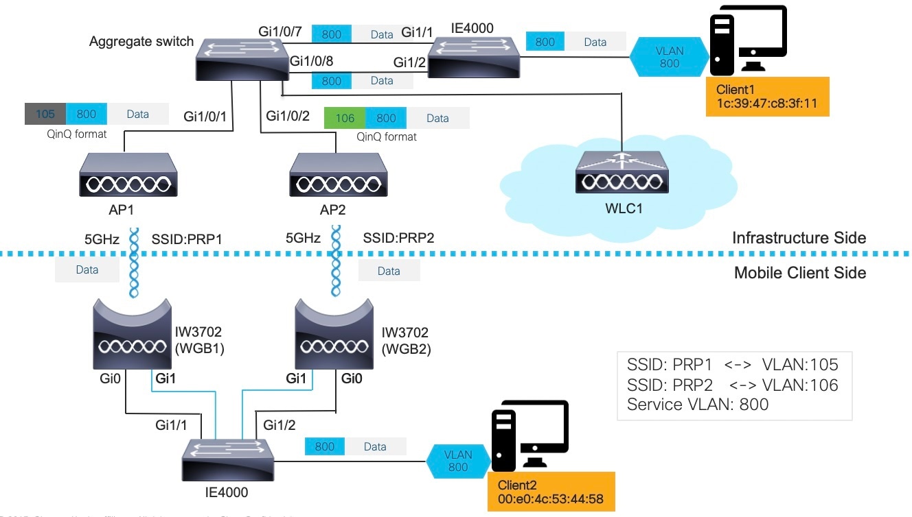
In above diagram, two wired clients communicate with each other. Client1 (1c39.47c8.3f11) resides on the infrastructure side while Client2 (00e0.4c53.4458) is on mobile client side.
Normally, wired Client2 will initialize the communication, using protocols such as DHCP, ARP, GARP, etc. But it is possible that wired Client2 is a passive client, which means it doesn’t make any talk until it receives packets from the infrastructure side, for example, downstream ARP from wired Client1.
The troubleshooting procedures will be described in the following two sections.
Troubleshooting Upstream Traffic
To troubleshoot upstream traffic, use the following procedure to track the packet hop by hop.
SUMMARY STEPS
- On client side IE4000, execute show mac address-table dynamic to check if wired Client2 is learned in the MAC address table with correct VLAN ID.
- On client side IE4000, execute show prp channel 1 detail to check if PRP ports are binding properly.
- On both WGBs, execute show bridge to check if the wired client MAC is learned in correct bridge group (bridge id).
- On WLC, execute show client detail <mac_of_client> to check if the client is learned and both WGBs details are learned on WLC.
- On infrastructure side aggregation switch, execute show mac address-table to check if Client2 is learned in two VLANs (PRP outer VLAN ID).
- On infrastructure side IE4000 switch, execute show mac address-table to check if Client2 MAC is learned in correct VLAN (inner VLAN).
DETAILED STEPS
| Step 1 |
On client side IE4000, execute show mac address-table dynamic to check if wired Client2 is learned in the MAC address table with correct VLAN ID. Example: |
| Step 2 |
On client side IE4000, execute show prp channel 1 detail to check if PRP ports are binding properly. Example:Execute show prp statistics egressPacketStatistics to check LAN-A and LAN-B egress counter. If both PRP ports are in UP state, you should see below sent counters increase equally. Example: |
| Step 3 |
On both WGBs, execute show bridge to check if the wired client MAC is learned in correct bridge group (bridge id). Example: |
| Step 4 |
On WLC, execute show client detail <mac_of_client> to check if the client is learned and both WGBs details are learned on WLC. Example: |
| Step 5 |
On infrastructure side aggregation switch, execute show mac address-table to check if Client2 is learned in two VLANs (PRP outer VLAN ID). Example: |
| Step 6 |
On infrastructure side IE4000 switch, execute show mac address-table to check if Client2 MAC is learned in correct VLAN (inner VLAN). Example: |
Troubleshooting Downstream Traffic
In IoT scenarios, multiple VLAN deployment is a typical solution. Customers assign different OT/IT devices with different VLAN IDs across the whole network.
To configure multi-VLAN network, see Configuring WGB Multiple Client VLAN for more information.
In real use cases, some device on WGB side may be a passive client, for example, a client with static IP address. When the peer device wants to make communication with the client, it broadcasts ARP within the segment.
The broadcasted ARP REQUEST will be flooded across the wired network and reach the infrastructure AP eventually. To preserve the VLAN ID, the infrastructure AP converts the broadcast address to a special multicast address by filling the VLAN ID into that address.
When the packet reaches WGB, WGB converts the special multicast to broadcast and recovers the VLAN ID, forwards the broadcast ARP REQUEST to corresponding GigabitEthernet sub-interface.
Note |
Flex mode AP in PRP solution only sends one broadcast or converted multicast packets over the air when broadcast-tagging configuration is enabled on IW3702 WGB. By default the Broadcast ARP requests packets are sent as unconverted in the Native VLAN only. The non-native broadcast packets to the wired clients behind WGB will be converted as multicast and native broadcast packets (non QinQ) will not be converted. The native VLAN broadcasts will still be sent with original broadcast address as the destination. On the WGB, the presence of ARP entries should be validated as a debugging step when roaming related PRP solutions are debugged in real time use case scenarios. |
To troubleshoot above scenario, use the following procedure to track the packet hop by hop.
SUMMARY STEPS
- Make capture on infrastructure AP side, and check that the ARP is in Q-in-Q format.
- Check following debug logs:
- Perform packet capture behind WGB to check if ARP is converted to broadcast in correct VLAN.
DETAILED STEPS
| Step 1 |
Make capture on infrastructure AP side, and check that the ARP is in Q-in-Q format. |
| Step 2 |
Check following debug logs: |
| Step 3 |
Perform packet capture behind WGB to check if ARP is converted to broadcast in correct VLAN. 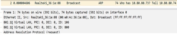
|
What to do next
For downstream unicast traffic, it’s similar but in the reverse way as upstream. On PRP-WGB-SW, execute show prp statistics ingressPacketStatistics.
Example:IE4K-Switch1#show prp statistics ingressPacketStatistics
PRP channel-group 1 INGRESS STATS: ingress
pkt lan a: 7359054 ingress pkt lan b:
10102696 ingress crc lan a: 0
ingress crc lan b: 0
ingress danp pkt acpt: 7376949 ingress
danp pkt dscrd: 1648270 ingress supfrm rcv
a: 4175430 ingress supfrm rcv b: 4262230
Single WGB Dual Radio PRP Redundancy Option
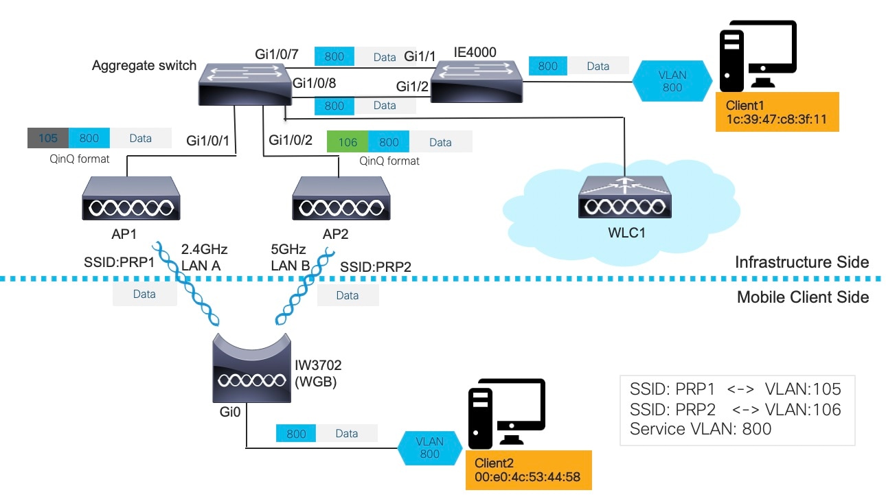
In above diagram, two wired clients communicate with each other. Client1 (1c:39:47:c8:3f:11) resides on the infrastructure side while Client2 (00:e0:4c:53:44:58) is on mobile client side.
Normally, wired Client2 will initialize the communication, using protocols such as DHCP, ARP, GARP, etc. But it is possible that wired Client2 is a passive client, which means it doesn’t make any talk until it receives packets from the infrastructure side, for example, downstream ARP from wired Client1.
The troubleshooting procedures will be described in the following two sections.
Troubleshooting Upstream Traffic
To troubleshoot upstream traffic, use the following procedure to track the packet hop by hop.
SUMMARY STEPS
- On client side IE4000 switch, execute show mac address-table dynamic to check if wired Client2 is learned in the MAC address table with correct VLAN ID.
- On WGB, execute show bridge to check if the wired client MAC is learned in correct bridge group (bridge id).
- On WGB, execute show dot11 wgb prp to check LAN-A and LAN-B egress counter. If both PRP radios are in UP state, you should see below sent counters increase equally.
- On WLC, execute show client detail <mac_of_client> to check if the client is learned and both WGBs details are learned on WLC.
- On infrastructure side aggregation switch, execute show mac address-table to check if Client2 is learned in two VLANs (PRP outer VLAN ID).
- On infrastructure side IE4000 switch, execute show mac address-table to check if Client2 MAC is learned in correct VLAN (inner VLAN).
DETAILED STEPS
| Step 1 |
On client side IE4000 switch, execute show mac address-table dynamic to check if wired Client2 is learned in the MAC address table with correct VLAN ID. Example: |
| Step 2 |
On WGB, execute show bridge to check if the wired client MAC is learned in correct bridge group (bridge id). Example: |
| Step 3 |
On WGB, execute show dot11 wgb prp to check LAN-A and LAN-B egress counter. If both PRP radios are in UP state, you should see below sent counters increase equally. Example: |
| Step 4 |
On WLC, execute show client detail <mac_of_client> to check if the client is learned and both WGBs details are learned on WLC. Example: |
| Step 5 |
On infrastructure side aggregation switch, execute show mac address-table to check if Client2 is learned in two VLANs (PRP outer VLAN ID). Example: |
| Step 6 |
On infrastructure side IE4000 switch, execute show mac address-table to check if Client2 MAC is learned in correct VLAN (inner VLAN). Example: |
Troubleshooting Downstream Traffic
In IoT scenarios, multiple VLAN deployment is a typical solution. Customers assign different OT/IT devices with different VLAN IDs across the whole network.
To configure multi-VLAN network, see Configuring WGB Multiple Client VLAN for more information.
In real use cases, some device on WGB side may be a passive client, for example, a client with static IP address. When the peer device wants to make communication with the client, it broadcasts ARP within the segment.
The broadcasted ARP REQUEST will be flooded across the wired network and reach the infrastructure AP eventually. To preserve the VLAN ID, the infrastructure AP converts the broadcast address to a special multicast address by filling the VLAN ID into that address.
When the packet reaches WGB, WGB converts the special multicast to broadcast and recovers the VLAN ID, forwards the broadcast ARP REQUEST to corresponding GigabitEthernet sub-interface.
To troubleshoot above scenario, use the following procedure to track the packet hop by hop.
SUMMARY STEPS
- Make capture on infrastructure AP side, and check that the ARP is in Q-in-Q format.
- Check following debug logs:
- Perform packet capture behind WGB to check if ARP is converted to broadcast in correct VLAN.
DETAILED STEPS
| Step 1 |
Make capture on infrastructure AP side, and check that the ARP is in Q-in-Q format. |
| Step 2 |
Check following debug logs: |
| Step 3 |
Perform packet capture behind WGB to check if ARP is converted to broadcast in correct VLAN.
|
What to do next
For downstream unicast traffic, it’s similar but in the reverse way as upstream. On WGB, execute show dot11 wgb prp to check LAN-A and LAN-B ingress counter. If both PRP radios are in UP state, you should see below received counters increase equally.
Example:Current work mode : dual-radio
Link selection mode : PRP
Available uplink count : 2
Index: 0 Status: UP Name: Dot11Radio0/Virtual-Dot11Radio0 Peer: 54a2.7474.d920
Index: 1 Status: UP Name: Dot11Radio1/Virtual-Dot11Radio1 Peer: 54a2.7474.d92f
================== PRP STATISTICS ==================
LAN-A Send : 23991
LAN-B Send : 23991
Send Difference : 0
LAN-A Rcv : 53223
LAN-B Rcv : 53223
Rcv Difference : 0
LAN-A Error : 0
LAN-B Error : 0
Discard : 0
Table Usage(INTERNAL) : 0
Max Dup Delay(INTERNAL): 0
====================================================
 Feedback