-
null
Visitor Connect
Workflow to Create Custom Splash Pages Using the Visitor Connect
Table 3-1 provides workflow to create custom splash pages using the visitor connect.
|
|
|
|---|---|
See the Prerequisites for Configuring Custom Splash Pages for more information. |
|
See the Social Application Configuration for more information. |
|
See the Creating a Splash Template Field for more information. |
|
See the Creating a Splash Template for more information. |
|
See the Assigning Splash Templates to Locations for more information. |
Prerequisites for Configuring Custom Splash Pages
- Configuring FlexConnect ACLs—This step is optional.
- Configuring WLAN for Web Passthrough Authentication
- Social Application Configuration
- Splash Template Configuration
Configuring FlexConnect ACLs
You need to configure FlexConnect Access Control Lists (ACLs) only for Flex mode deployments. To configure FlexConnect ACLs, follow these steps:
Step 1![]() Choose Security > Access Control Lists > FlexConnect Access Control Lists from the Controller UI.
Choose Security > Access Control Lists > FlexConnect Access Control Lists from the Controller UI.
The FlexConnect ACL page is displayed. This page lists all the FlexConnect ACLs configured on the controller. This page also shows the FlexConnect ACLs created on the corresponding controller. To remove an ACL, hover your mouse over the blue drop-down arrow adjacent to the corresponding ACL name and choose Remove.
Step 2![]() Add a new ACL by clicking New.
Add a new ACL by clicking New.
The Access Control Lists > New page is displayed.
Step 3![]() In the Access Control List Name text box, enter a name for the new ACL. You can enter up to 32 alphanumeric characters.
In the Access Control List Name text box, enter a name for the new ACL. You can enter up to 32 alphanumeric characters.
Step 5![]() When the Access Control Lists page reappears, click the name of the new ACL.
When the Access Control Lists page reappears, click the name of the new ACL.
When the Access Control Lists > Edit page appears, click Add New Rule.
The Access Control Lists > Rules > New page is displayed.
Step 6![]() Configure a rule for this ACL as follows:
Configure a rule for this ACL as follows:
a.![]() The controller supports up to 64 rules for each ACL. These rules are listed in order from 1 to 64. In the Sequence text box, enter a value (between 1 and 64) to determine the order of this rule in relation to any other rules defined for this ACL.
The controller supports up to 64 rules for each ACL. These rules are listed in order from 1 to 64. In the Sequence text box, enter a value (between 1 and 64) to determine the order of this rule in relation to any other rules defined for this ACL.

Note![]() If rules 1 through 4 are already defined and you add rule 29, it is added as rule 5. If you add or change a sequence number of a rule, the sequence numbers of the other rules are automatically adjusted to maintain a continuous sequence. For instance, if you change a rule’s sequence number from 7 to 5, the rules with sequence numbers 5 and 6 are automatically reassigned as 6 and 7, respectively.
If rules 1 through 4 are already defined and you add rule 29, it is added as rule 5. If you add or change a sequence number of a rule, the sequence numbers of the other rules are automatically adjusted to maintain a continuous sequence. For instance, if you change a rule’s sequence number from 7 to 5, the rules with sequence numbers 5 and 6 are automatically reassigned as 6 and 7, respectively.
b.![]() From the Source drop-down list, choose one of these options to specify the source of the packets to which this ACL is applicable:
From the Source drop-down list, choose one of these options to specify the source of the packets to which this ACL is applicable:
–![]() Any—Any source (This is the default value.)
Any—Any source (This is the default value.)
–![]() IP Address—A specific source. If you choose this option, enter the IP address and netmask of the source in the corresponding text boxes.
IP Address—A specific source. If you choose this option, enter the IP address and netmask of the source in the corresponding text boxes.
c.![]() From the Destination drop-down list, choose one of these options to specify the destination of the packets to which this ACL applies:
From the Destination drop-down list, choose one of these options to specify the destination of the packets to which this ACL applies:
–![]() Any—Any destination (This is the default value.)
Any—Any destination (This is the default value.)
–![]() IP Address—A specific destination. If you choose this option, enter the IP address and netmask of the destination in the text boxes.
IP Address—A specific destination. If you choose this option, enter the IP address and netmask of the destination in the text boxes.
d.![]() From the Protocol drop-down list, choose the protocol ID of the IP packets to be used for this ACL. The protocol options that you can use are the following:
From the Protocol drop-down list, choose the protocol ID of the IP packets to be used for this ACL. The protocol options that you can use are the following:
–![]() Any—Any protocol (This is the default value.)
Any—Any protocol (This is the default value.)
–![]() ICMP—Internet Control Message Protocol
ICMP—Internet Control Message Protocol
–![]() ESP—IP Encapsulating Security Payload
ESP—IP Encapsulating Security Payload
–![]() GRE—Generic Routing Encapsulation
GRE—Generic Routing Encapsulation
–![]() IP in IP—Permits or denies IP-in-IP packets
IP in IP—Permits or denies IP-in-IP packets
–![]() Eth Over IP—Ethernet-over-Internet Protocol
Eth Over IP—Ethernet-over-Internet Protocol
–![]() OSPF—Open Shortest Path First
OSPF—Open Shortest Path First
–![]() Other—Any other Internet-Assigned Numbers Authority (IANA) protocol
Other—Any other Internet-Assigned Numbers Authority (IANA) protocol
Note![]() If you choose Other, enter the number of the desired protocol in the Protocol text box. You can find the list of available protocols in the INAI website.
If you choose Other, enter the number of the desired protocol in the Protocol text box. You can find the list of available protocols in the INAI website.
The controller can permit or deny only the IP packets in an ACL. Other types of packets (such as Address Resolution Protocol (ARP) packets) cannot be specified. If you chose TCP or UDP, two additional parameters, Source Port and Destination Port, are displayed. These parameters enable you to choose a specific source port and destination port or port range. The port options are used by applications that send and receive data to and from the networking stack. Some ports are designated for certain applications, such as Telnet, SSH, HTTP, and so on.
e.![]() From the DSCP drop-down list, choose one of these options to specify the differentiated services code point (DSCP) value of this ACL. DSCP is an IP header text box that can be used to define the quality of service across the Internet.
From the DSCP drop-down list, choose one of these options to specify the differentiated services code point (DSCP) value of this ACL. DSCP is an IP header text box that can be used to define the quality of service across the Internet.
–![]() Any—Any DSCP (This is the default value.)
Any—Any DSCP (This is the default value.)
–![]() Specific—A specific DSCP from 0 to 63, which you enter in the DSCP text box
Specific—A specific DSCP from 0 to 63, which you enter in the DSCP text box
f.![]() From the Action drop-down list, choose Deny to cause this ACL to block packets, or Permit to cause this ACL to allow packets. The default value is Deny.
From the Action drop-down list, choose Deny to cause this ACL to block packets, or Permit to cause this ACL to allow packets. The default value is Deny.
The Access Control Lists > Edit page is displayed on which the rules for this ACL are shown.
h.![]() Repeat this procedure to add additional rules, if any, for this ACL as listed in the table below:
Repeat this procedure to add additional rules, if any, for this ACL as listed in the table below:
|
|
|
|
|
|
|
|
|
|
|---|---|---|---|---|---|---|---|---|
Step 7![]() Click Save Configuration.
Click Save Configuration.
Configuring WLAN for Web Passthrough Authentication
For providing network access to the customers, you need to configure WLAN on the Cisco Wireless LAN Controller (WLC). For this you need to set up the Web Passthrough on the layer three security of WLAN for CMX Visitor Connect.
To configure Web Passthrough configuration, follow these steps:
Step 1![]() Define an Access Control List (ACL) for pre-authentication from the Controller UI to allow the traffic to MSE IP address and to resolve DNS when in WENAUTH_REQD state. All other traffic is blocked from clients connecting to SSID. For more information about configuring ACLs, see the Cisco Wireless LAN Configuration Guide at: http://www.cisco.com/en/US/products/ps12722/products_installation_and_configuration_guides_list.html
Define an Access Control List (ACL) for pre-authentication from the Controller UI to allow the traffic to MSE IP address and to resolve DNS when in WENAUTH_REQD state. All other traffic is blocked from clients connecting to SSID. For more information about configuring ACLs, see the Cisco Wireless LAN Configuration Guide at: http://www.cisco.com/en/US/products/ps12722/products_installation_and_configuration_guides_list.html
Note![]() The ACL is not required for Flex deployments.
The ACL is not required for Flex deployments.
Step 2![]() Choose WLANs to open the WLANs page from the Controller UI.
Choose WLANs to open the WLANs page from the Controller UI.
Step 3![]() Click the ID number of the desired WLAN to open the WLANs > Edit page.
Click the ID number of the desired WLAN to open the WLANs > Edit page.
Step 4![]() Choose Security > Layer 2 tab.
Choose Security > Layer 2 tab.
Step 5![]() From the Layer 2 Security drop-down list, choose None.
From the Layer 2 Security drop-down list, choose None.
Step 7![]() Choose the Security and Layer 3 tabs to open the WLANs > Edit (Security > Layer 3) page.
Choose the Security and Layer 3 tabs to open the WLANs > Edit (Security > Layer 3) page.
Figure 3-1 Web Passthrough Setting
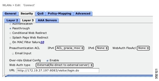
Step 8![]() Select the Web Policy check box.
Select the Web Policy check box.
Step 9![]() Configure Preauthentication ACL to restrict the clients from accessing Internet and rest of the network except MSE and DNS resolution. To redirect the user to a site external to the controller, choose the ACL that was configured from the Preauthentication ACL drop-down list.
Configure Preauthentication ACL to restrict the clients from accessing Internet and rest of the network except MSE and DNS resolution. To redirect the user to a site external to the controller, choose the ACL that was configured from the Preauthentication ACL drop-down list.
An Access Control List (ACL) is a set of rules used to limit access to a particular interface. You can create a preauthentication ACL for web authentication. Such an ACL could be used to allow certain types of traffic before authentication is complete. Both IPV4 and IPV6 are supported. IPV6 ACLs support the same options as IPV4 ACLs including source, destination, source and destination ports.
Define an ACL for Pre-authentication to allow the traffic to MSE IP address and to resolve DNS when in WEBAUTH_REQD state. All other traffic will be blocked from clients connecting to SSID.
The Pre-Authentication Flex Connect ACL is required for flex mode deployments. For more information, see the Configuring FlexConnect ACLs.
Step 10![]() To override global authentication configuration web authentication pages, select the Over-ride Global Config check box.
To override global authentication configuration web authentication pages, select the Over-ride Global Config check box.
Step 11![]() To define the web authentication pages for wireless guest users, choose External from the Web Auth Type drop-down list. This redirects clients to an external server for authentication. If you choose this option, you must also enter the URL of the external server in the URL text box.
To define the web authentication pages for wireless guest users, choose External from the Web Auth Type drop-down list. This redirects clients to an external server for authentication. If you choose this option, you must also enter the URL of the external server in the URL text box.
Note![]() The external redirection URL should point to Visitor Connect captive portal URL.
The external redirection URL should point to Visitor Connect captive portal URL.
Step 12![]() Enter the URL of the splash page in the URL text box. For example, you can enter:
Enter the URL of the splash page in the URL text box. For example, you can enter:
http://<MSE>:8083/visitor/login.do
Note![]() If MSE is behind the firewall, you need to modify security rules to allow traffic to 8083 port on MSE. Otherwise splash pages will not be displayed to the visitor.
If MSE is behind the firewall, you need to modify security rules to allow traffic to 8083 port on MSE. Otherwise splash pages will not be displayed to the visitor.
Step 13![]() Click Apply to commit your changes.
Click Apply to commit your changes.
Step 14![]() Click Save Configuration to save the changes.
Click Save Configuration to save the changes.
Note![]() Visitor Connect redirection requires special configuration on WLC for iOS devices and you can do it using this command: config network web-auth captive-bypass enable.For more information, see the http://www.cisco.com/c/en/us/td/docs/wireless/controller/7-4/configuration/guides/consolidated/b_cg74_CONSOLIDATED/b_cg74_CONSOLIDATED_chapter_01010101.html
Visitor Connect redirection requires special configuration on WLC for iOS devices and you can do it using this command: config network web-auth captive-bypass enable.For more information, see the http://www.cisco.com/c/en/us/td/docs/wireless/controller/7-4/configuration/guides/consolidated/b_cg74_CONSOLIDATED/b_cg74_CONSOLIDATED_chapter_01010101.html
Social Application Configuration
The social authentication requires venue owners to create an application on social network provider such as Facebook, LinkedIn, and Google+. Once the social application is created, it provides an application ID and secret key that is required by the CMX Visitor Connect to successfully authenticate the visitors.
While creating social application, the venue owner has to provide the following information:

- Facebook application link: https://developers.facebook.com/apps
Note![]() Disable the Sandbox Mode from the Facebook Developers page while creating Facebook application ID and secret key.
Disable the Sandbox Mode from the Facebook Developers page while creating Facebook application ID and secret key.
Note![]() Make sure that your App is made available for Public use. Without this, authentications will fail.
Make sure that your App is made available for Public use. Without this, authentications will fail.
- LinkedIn Apps link: https://www.linkedin.com/secure/developer
- Google+ Apps link: https://console.developers.google.com/project
You can now create social connectors as part of splash template creation flow. See Splash Template Configuration for more information.
Note![]() The client authentication fails if the MSE has a private IP address and the MSE IP Address is used in the social application configuration. To fix the problem, assign a DNS name for MSE and use the MSE DNS Name instead of MSE IP address in the social application configuration. Make sure that MSE DNS name is used as the external portal URL in the guest SSID configuration.
The client authentication fails if the MSE has a private IP address and the MSE IP Address is used in the social application configuration. To fix the problem, assign a DNS name for MSE and use the MSE DNS Name instead of MSE IP address in the social application configuration. Make sure that MSE DNS name is used as the external portal URL in the guest SSID configuration.
Note![]() You need to enable Google Cloud Storage JSON API in order to get the API key that is required in the CMX Visitor Connect Splash template set up. To activate this, click Activate that is next to Google Cloud Storage JSON API in the Services tab.
You need to enable Google Cloud Storage JSON API in order to get the API key that is required in the CMX Visitor Connect Splash template set up. To activate this, click Activate that is next to Google Cloud Storage JSON API in the Services tab.
Splash Template Configuration
Splash templates allow you to design splash pages for your guest portal. The following steps are involved in creating the splash template:
- (Optional) Create Template Fields—See Template Fields for more information.
- (Optional) Create Social Connectors—See Social Connectors
- Create Splash Templates—Splash Templates
- Assign Splash Templates—Assigning Splash Templates to Locations
Template Fields
Use the template fields to collect information from visitors at the time if registration. The template fields can be name, gender, phone number, etc.
Creating a Splash Template Field
To create a splash template field, follow these steps:
Step 1![]() Choose Visitor Connect > Templates Fields from the left side bar menu.
Choose Visitor Connect > Templates Fields from the left side bar menu.
The Add/Edit Splash Template Field appears.
Step 3![]() Enter the name of the field you want to create in the Name text box.
Enter the name of the field you want to create in the Name text box.
Step 4![]() Select the field type: Text and List.
Select the field type: Text and List.
Step 5![]() Click Submit to apply your changes, or Cancel to discard the creation of field.
Click Submit to apply your changes, or Cancel to discard the creation of field.
The newly added field appears in the Splash Template Fields group box.
Editing a Template Field
To edit a splash template field, follow these steps:
Step 1![]() Choose Visitor Connect > Template Fields from the left sidebar menu.
Choose Visitor Connect > Template Fields from the left sidebar menu.
Step 2![]() Highlight the field that you want to edit in the Splash Template Fields group box and click Edit.
Highlight the field that you want to edit in the Splash Template Fields group box and click Edit.
Step 3![]() Make the necessary changes in the Add/Edit Splash Template Field group box and click Submit.
Make the necessary changes in the Add/Edit Splash Template Field group box and click Submit.
Deleting a Template Field
To delete a splash template field, follow these steps:
Step 1![]() Choose Visitor Connect > Template Fields from the left sidebar menu.
Choose Visitor Connect > Template Fields from the left sidebar menu.
Step 2![]() Highlight the field that you want to delete in the splash Template Fields group box and click Delete.
Highlight the field that you want to delete in the splash Template Fields group box and click Delete.
Step 3![]() Click OK to confirm the deletion in the Delete Confirmation dialog box, or Close to close the page without making any changes.
Click OK to confirm the deletion in the Delete Confirmation dialog box, or Close to close the page without making any changes.
Social Connectors
The Visitor Connect enables the venue owners to offer Wi-Fi access to their customers using the social network authentication. This requires venue owners to create an application on the social network sites such as Facebook, Google+, and LinkedIn. See the Social Connectors Set up for more information.
Note![]() You can use Facebook, Google+, and LinkedIn sites to create social connectors. The visitors can use credentials for any one of these connectors.
You can use Facebook, Google+, and LinkedIn sites to create social connectors. The visitors can use credentials for any one of these connectors.
Configuring the Social Connector
You can use the social connector menu to create multiple social connectors. To configure the social connector, follow these steps:
Step 1![]() Choose Visitor Connect > Social Connector from the left side bar menu.
Choose Visitor Connect > Social Connector from the left side bar menu.
The Add/Edit Social Connectors group box appears.
Step 3![]() Enter the social connector name in the Connector Name text box. You can create a maximum of 10 social connectors.
Enter the social connector name in the Connector Name text box. You can create a maximum of 10 social connectors.
Step 4![]() To provide Facebook authentication, enter the Facebook APP ID that you received after creating Facebook application in the Facebook text box.
To provide Facebook authentication, enter the Facebook APP ID that you received after creating Facebook application in the Facebook text box.
Step 5![]() To provide LinkedIn authentication, enter the LinkedIn API key that you received in the Linkedin text box.
To provide LinkedIn authentication, enter the LinkedIn API key that you received in the Linkedin text box.
Step 6![]() To provide Google+ authentication, enter the Google API client ID and Google API Key in the Google+ text box.
To provide Google+ authentication, enter the Google API client ID and Google API Key in the Google+ text box.
Editing a Social Connector Entry
To edit a social connector entry, follow these steps:
Step 1![]() Choose Visitor Connect > Social Connector from the left side bar menu.
Choose Visitor Connect > Social Connector from the left side bar menu.
Step 2![]() Click to highlight a social connector entry in the Social Connectors group box and click Edit.
Click to highlight a social connector entry in the Social Connectors group box and click Edit.
Step 3![]() Make the necessary changes in the Add/Edit Social Connectors group box and click Submit.
Make the necessary changes in the Add/Edit Social Connectors group box and click Submit.
Deleting a Social Connector
To delete a social connector, follow these steps:
Step 1![]() Choose Visitor Connect > Social Connector from the left side bar menu.
Choose Visitor Connect > Social Connector from the left side bar menu.
Step 2![]() Click to highlight a social connector entry in the Social Connectors group box and click Delete.
Click to highlight a social connector entry in the Social Connectors group box and click Delete.
Step 3![]() Click OK to confirm the deletion, or Close to close the page without making any changes.
Click OK to confirm the deletion, or Close to close the page without making any changes.
Splash Templates
You can create location aware splash templates to serve different locations or zones. You can create multiple splash templates and assign them to different Points of Interest.
Creating a Splash Template
To create a splash template, follow these steps:
Step 1![]() Choose Visitor Connect from the left sidebar menu.
Choose Visitor Connect from the left sidebar menu.
The Splash Template Configuration page appears.
Step 2![]() Click Create in the Splash Templates group box.
Click Create in the Splash Templates group box.
The Add/Edit Splash Template wizard appears.
Step 3![]() In the Template Name text, enter a name for the splash page.
In the Template Name text, enter a name for the splash page.
Step 4![]() From the Background drop-down list, choose a predefined background for your splash page. To set the background of your choice, choose Custom from the Template Background drop-list and click Click to upload an image to upload an image for the splash page background.
From the Background drop-down list, choose a predefined background for your splash page. To set the background of your choice, choose Custom from the Template Background drop-list and click Click to upload an image to upload an image for the splash page background.
Step 5![]() From the Form Fields list, choose the field(s) that you want to include in the splash page. The fields populate if you have already created template fields using the Visitor Connect > Template Fields > Create menu. If you have not created template fields, you can you can click Create Template Fields and follow steps provided in Creating a Splash Template Field.
From the Form Fields list, choose the field(s) that you want to include in the splash page. The fields populate if you have already created template fields using the Visitor Connect > Template Fields > Create menu. If you have not created template fields, you can you can click Create Template Fields and follow steps provided in Creating a Splash Template Field.
Step 6![]() Provide details for the splash fields that you choose in the Form Fields list. For template fields of type List, provide the list of choices you want to provide.
Provide details for the splash fields that you choose in the Form Fields list. For template fields of type List, provide the list of choices you want to provide.
Step 7![]() In the Terms&Conditions text box, enter the terms and conditions that you want to display in the splash page.
In the Terms&Conditions text box, enter the terms and conditions that you want to display in the splash page.
Step 8![]() In Header text box, enter any welcome information for the customer. For example you can enter 'Welcome to XYZ mall'.
In Header text box, enter any welcome information for the customer. For example you can enter 'Welcome to XYZ mall'.
Step 9![]() In Footer text box, you can enter any disclaimer.
In Footer text box, you can enter any disclaimer.
Step 10![]() Click Next to configure advertisements that you want to display in the splash page.
Click Next to configure advertisements that you want to display in the splash page.
Step 11![]() In the Ad Script text box, provide html script that points to the advertisement server or static HTML pages, or HTML page with animated graphics.
In the Ad Script text box, provide html script that points to the advertisement server or static HTML pages, or HTML page with animated graphics.
This is a sample advertisement configuration that points to a YouTube URL. You can also provide any HTML also.
<iframe width="100 %" height="100%" src="//www.youtube.com/embed/imW392e6XR0" frameborder="0" allowfullscreen></iframe>.
Note![]() Advertisement is an optional step. If you do not specify any URL for the advertisement, the advertisement page will be skipped during the guest on boarding.
Advertisement is an optional step. If you do not specify any URL for the advertisement, the advertisement page will be skipped during the guest on boarding.
Step 12![]() Click Next to configure social authentication for visitors log in.
Click Next to configure social authentication for visitors log in.
Note![]() Social authentication is optional. If you do not select any social connector, the Social Authentication page is skipped during the guest on-boarding.
Social authentication is optional. If you do not select any social connector, the Social Authentication page is skipped during the guest on-boarding.
Step 13![]() In the Header text box, enter the information that you want to display in the Social authentication page. For example, you can enter 'Congratulations! You are on the Wi-Fi network of XYZ'.
In the Header text box, enter the information that you want to display in the Social authentication page. For example, you can enter 'Congratulations! You are on the Wi-Fi network of XYZ'.
Step 14![]() From the Social Connector drop-down list, choose the social connector. The social connector field populates if you have already created using the Visitor Connect > Social Connectors menu. If you have not done, you can click Create Social Connectors and follow steps provided in the Configuring the Social Connector procedure.
From the Social Connector drop-down list, choose the social connector. The social connector field populates if you have already created using the Visitor Connect > Social Connectors menu. If you have not done, you can click Create Social Connectors and follow steps provided in the Configuring the Social Connector procedure.
Step 15![]() Select the corresponding authentication type from Social Auth check box.
Select the corresponding authentication type from Social Auth check box.
Step 16![]() Enter the information in the footer text box.
Enter the information in the footer text box.
Step 18![]() If you want to redirect users to a specific page after successful authentication, enter URL in the Redirect URL text box.
If you want to redirect users to a specific page after successful authentication, enter URL in the Redirect URL text box.
Assigning Splash Templates to Locations
You can assign the splash template to one or more location inside the map. This enables venue owners to give location aware network access to the customer.
To assign a splash template to a floor, follow these steps:
Step 1![]() Choose Maps from the left sidebar menu.
Choose Maps from the left sidebar menu.
Note![]() Ensure that you have updated maps from the PI. See the Updating Maps from the Prime Infrastructure for more information.
Ensure that you have updated maps from the PI. See the Updating Maps from the Prime Infrastructure for more information.
Step 2![]() In the right pane, choose Maps > System Campus > desired Building > desired Floor.
In the right pane, choose Maps > System Campus > desired Building > desired Floor.
Note![]() This inheritance relationship applies to all tiers of locations and not just buildings to floor.
This inheritance relationship applies to all tiers of locations and not just buildings to floor.
Note![]() If you assign a splash template to a building, all the floors defined under that building inherits the splash template. If you have a splash template defined at both building and floor, the floor splash template is used.
If you assign a splash template to a building, all the floors defined under that building inherits the splash template. If you have a splash template defined at both building and floor, the floor splash template is used.
Step 3![]() From the Visitor Connect Splash Template drop-down list, choose the splash page template that you want to assign to the selected floor.
From the Visitor Connect Splash Template drop-down list, choose the splash page template that you want to assign to the selected floor.
Updating Maps from the Prime Infrastructure
If you modify the campus, building, or floor on the PI, you have to update them in the CMX Connect & Engage. To update maps from the Prime Infrastructure, follow these steps:
Step 1![]() Choose Maps from the left sidebar menu.
Choose Maps from the left sidebar menu.
Step 2![]() Click Update Maps from PI in the right pane.
Click Update Maps from PI in the right pane.
Step 3![]() Click Ok in the Update Confirmation dialog box.
Click Ok in the Update Confirmation dialog box.
Visitor Connect Report
Monitoring the Visitor Details
To monitor the visitor details, follow these steps:
Step 1![]() From the left side bar menu, choose Summary.
From the left side bar menu, choose Summary.
Step 2![]() To monitor the visitor details, click the Visitor Connect tab in the right pane.
To monitor the visitor details, click the Visitor Connect tab in the right pane.
Figure 3-2 Hourly Trend for New Visitors
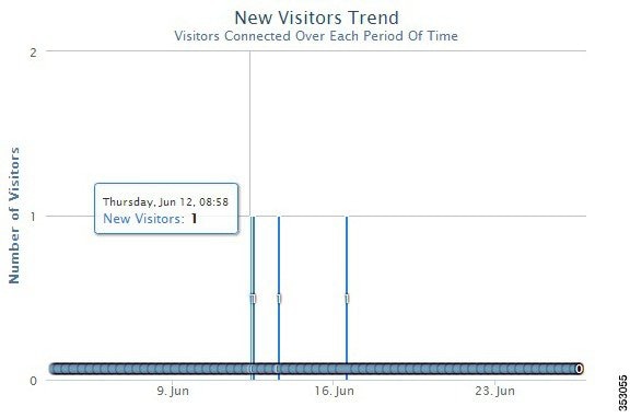
Figure 3-3 Hourly Trend for Total Visitors
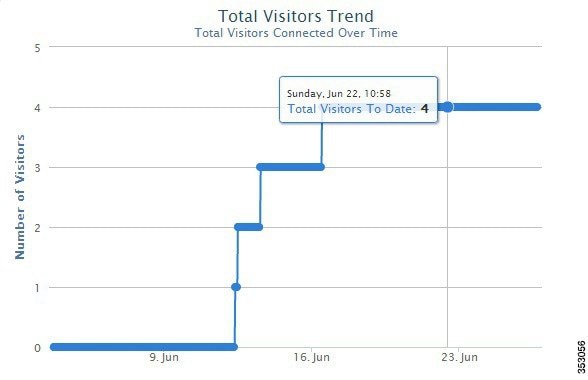
Figure 3-4 Daily Trend for New Visitors

Figure 3-5 Daily Trend for Total Visitors
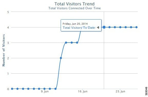
Figure 3-6 Weekly Trend for New Visitors

Figure 3-7 Weekly Trend for Total Visitors
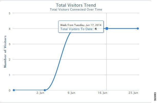
Figure 3-8 Monthly Trend for New Visitors

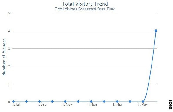
Figure 3-9 Monthly Trend for Total Visitors
Step 3![]() The Active Visitors table at the bottom of the page lists the registration information about active visitors based on the splash template configuration. This information in the table can be sorted and filtered.
The Active Visitors table at the bottom of the page lists the registration information about active visitors based on the splash template configuration. This information in the table can be sorted and filtered.
Step 4![]() Click Export to CSV > Export Active Visitors to export all active visitors details. Click Export to CSV > Export All Visitors to export all visitors details.
Click Export to CSV > Export Active Visitors to export all active visitors details. Click Export to CSV > Export All Visitors to export all visitors details.
Visitor Policy Configuration
Visitor policy allows MSE to differentiate between different types of visitors. Using visitor policy, you can define the network usage limit for different types of users. The following are the user groups available:
- Basic users—When a visitor is redirected to Visitor Connect splash page, he is given an option to login with social network ID. If the visitor does not login with the social network ID, they are placed into the basic group. You can assign usage limit to the visitors and after reaching the usage limit for that day, the user will be asked to log in the next day because the counting of usage starts from 00.00AM. The default usage limit is 300 MB.
- Social users—If the visitor logs in with social network ID, they are placed into the social group. This group also includes Facebook Wi-Fi users. By default, The default usage limit is 3GB per day.
Note![]() Visitor policy configuration applies to both the Visitor connect and Facebook Wi-Fi.
Visitor policy configuration applies to both the Visitor connect and Facebook Wi-Fi.
Enabling Visitor Policy and Editing the User Groups
To enable visitor policy and editing the user groups, follow these steps:
Step 1![]() Choose Visitor Policy from the left sidebar menu.
Choose Visitor Policy from the left sidebar menu.
Step 2![]() Click Enable in the Visitor Policy group box.
Click Enable in the Visitor Policy group box.
Step 3![]() Click Edit icon or Usage Cap number to edit the usage limit.
Click Edit icon or Usage Cap number to edit the usage limit.
Step 4![]() Click outside to save the usage number.
Click outside to save the usage number.
 Feedback