- Preface
- Chapter 1: Overview
- Chapter 2: Adding and Deleting Systems
- Chapter 3: Synchronizing Mobility Services Engines
- Chapter 4: Configuring and Viewing System Properties
- Chapter 5: Managing Users and Groups
- Chapter 6: Configuring wIPS and Profiles
- Chapter 7: Monitoring the System and Services
- Chapter 8: Performing Maintenance Operations
- Appendix A: wIPS Policy Alarm Encyclopedia
- Appendix B: Rogue Management
- Appendix C: Radio Resource Management
- Appendix D : MSE System and Appliance Hardening Guidelines
- Index
Cisco Adaptive Wireless Intrusion Prevention System Configuration Guide Release 7.0.201.0
Bias-Free Language
The documentation set for this product strives to use bias-free language. For the purposes of this documentation set, bias-free is defined as language that does not imply discrimination based on age, disability, gender, racial identity, ethnic identity, sexual orientation, socioeconomic status, and intersectionality. Exceptions may be present in the documentation due to language that is hardcoded in the user interfaces of the product software, language used based on RFP documentation, or language that is used by a referenced third-party product. Learn more about how Cisco is using Inclusive Language.
- Updated:
- March 17, 2015
Chapter: Chapter 6: Configuring wIPS and Profiles
Configuring wIPS and Profiles
This chapter describes how to configure wIPS profiles and those items that must be configured in conjunction to operate wIPS.
This chapter contains the following sections:
•![]() Configuring Access Points for wIPS Monitor Mode
Configuring Access Points for wIPS Monitor Mode
Overview of wIPS Configuration and Profile Management
Configuration of wIPS profiles follows a chained hierarchy starting with Wcs, which is used for profile viewing and modification. The actual profiles are stored within the wIPS service running on the mobility services engine (MSE).
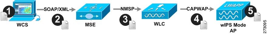
From the wIPS service on the mobility services engine, profiles are propagated to specific controllers, which in turn communicate this profile transparently to wIPS mode access points associated to that respective controller. (See Figure 6-1).
Figure 6-1 Configuration and Update of wIPS Profiles

Note ![]() If your wIPS deployment consists of a controller, access point, and MSE, you must set all the three entities to the UTC timezone.
If your wIPS deployment consists of a controller, access point, and MSE, you must set all the three entities to the UTC timezone.
When a configuration change to a wIPS profile is made at WCS and applied to a set of mobility services engines and controllers, the following occurs:
1. ![]() The configuration profile is modified on WCS and version information is updated.
The configuration profile is modified on WCS and version information is updated.
2. ![]() An XML-based profile is pushed to the wIPS engine running on the mobility services engine. This update occurs over the SOAP/XML protocol.
An XML-based profile is pushed to the wIPS engine running on the mobility services engine. This update occurs over the SOAP/XML protocol.
3. ![]() The wIPS engine on the mobility services engine updates each controller associated with that profile by pushing out the configuration profile over NMSP.
The wIPS engine on the mobility services engine updates each controller associated with that profile by pushing out the configuration profile over NMSP.
Note ![]() A controller is associated to a single configuration profile. All wIPS mode access points connected to that controller share the same wIPS configuration.
A controller is associated to a single configuration profile. All wIPS mode access points connected to that controller share the same wIPS configuration.
4. ![]() The controller receives the updated wIPS profile, stores it into NVRAM (replacing any previous revision of the profile) and propagates the updated profile to its associated wIPS access points using CAPWAP control messages.
The controller receives the updated wIPS profile, stores it into NVRAM (replacing any previous revision of the profile) and propagates the updated profile to its associated wIPS access points using CAPWAP control messages.
5. ![]() A wIPS mode access point receives the updated profile from the controller and applies the modifications to its wIPS software engine.
A wIPS mode access point receives the updated profile from the controller and applies the modifications to its wIPS software engine.
Note ![]() The mobility services engine can only be configured from one WCS.
The mobility services engine can only be configured from one WCS.
Before you can configure wIPS profiles you must do the following:
1. ![]() Install a mobility services engine (if one is not already operating in the network). Refer to the Cisco 3350 Mobility Services Engine Getting Started Guide or Cisco 3310 Mobility Services Engine Getting Started Guide:
Install a mobility services engine (if one is not already operating in the network). Refer to the Cisco 3350 Mobility Services Engine Getting Started Guide or Cisco 3310 Mobility Services Engine Getting Started Guide:
http://www.cisco.com/en/US/products/ps9742/prod_installation_guides_list.html
2. ![]() Add the mobility services engine to WCS (if not already added). See the "Adding and Deleting Systems" section on page 2-1.
Add the mobility services engine to WCS (if not already added). See the "Adding and Deleting Systems" section on page 2-1.
3. ![]() Configure access points to operate in wIPS monitor mode. See the "Configuring Access Points for wIPS Monitor Mode" section.
Configure access points to operate in wIPS monitor mode. See the "Configuring Access Points for wIPS Monitor Mode" section.
4. ![]() Configure wIPS profiles. See the "Configuring wIPS Profiles" section.
Configure wIPS profiles. See the "Configuring wIPS Profiles" section.
This section contains the following topics:
•![]() Configuring Access Points for wIPS Monitor Mode
Configuring Access Points for wIPS Monitor Mode
Configuring Access Points for wIPS Monitor Mode
Note![]() •
•![]() Only Cisco Aironet 1130, 1140, 1240, 1250, 3502E and 3502I Series Access Points support wIPS monitor mode.
Only Cisco Aironet 1130, 1140, 1240, 1250, 3502E and 3502I Series Access Points support wIPS monitor mode.
•![]() The wIPS sub mode is supported only when access point mode is Monitor, Local or HREAP. But for 1130 and 1240 access points, wIPS is supported only in Monitor Mode.
The wIPS sub mode is supported only when access point mode is Monitor, Local or HREAP. But for 1130 and 1240 access points, wIPS is supported only in Monitor Mode.
To configure an access point to operate in wIPS monitor mode, follow these steps:
Step 1 ![]() In WCS, choose Configure > Access Points.
In WCS, choose Configure > Access Points.
Step 2 ![]() Click the 802.11a or 802.11b/g radio link (see Figure 6-2).
Click the 802.11a or 802.11b/g radio link (see Figure 6-2).
Figure 6-2 Configure > Access Points > Radio

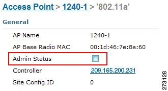
Step 3 ![]() On the access point page, unselect the Admin Status check box to disable the radio.
On the access point page, unselect the Admin Status check box to disable the radio.
Figure 6-3 Access Points > Radio
Step 4 ![]() Click Save.
Click Save.
Note ![]() Repeat these steps for each radio on an access point that is to be configured for wIPS monitor mode.
Repeat these steps for each radio on an access point that is to be configured for wIPS monitor mode.
Step 5 ![]() Once the radios are disabled, choose Configure > Access Points and then click the name of the access point whose radio you just disabled.
Once the radios are disabled, choose Configure > Access Points and then click the name of the access point whose radio you just disabled.
Step 6 ![]() In the access point dialog box, choose Monitor Mode from the AP Mode drop-down list. (see Figure 6-4).
In the access point dialog box, choose Monitor Mode from the AP Mode drop-down list. (see Figure 6-4).
Figure 6-4 Configure > Access Points > AP Name
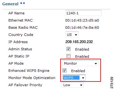
Step 7 ![]() Select the Enabled check box for the Enhanced WIPS Engine.
Select the Enabled check box for the Enhanced WIPS Engine.
Step 8 ![]() From the Monitor Mode Optimization drop-down list, choose WIPS.
From the Monitor Mode Optimization drop-down list, choose WIPS.
Step 9 ![]() Click Save.
Click Save.
Step 10 ![]() Click OK when prompted to reboot the access point.
Click OK when prompted to reboot the access point.
Step 11 ![]() To reenable the access point radio, choose Configure > Access Points.
To reenable the access point radio, choose Configure > Access Points.
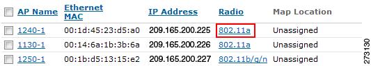
Step 12 ![]() Click the appropriate access point radio (see Figure 6-5).
Click the appropriate access point radio (see Figure 6-5).
Figure 6-5 Configure > Access Points > Radio
Step 13 ![]() In the radio configuration pane, select the Admin Status Enabled check box.
In the radio configuration pane, select the Admin Status Enabled check box.
Step 14 ![]() Click Save.
Click Save.
Repeat this for each access point and each respective radio configured for wIPS monitor mode.
Configuring wIPS Profiles
By default, the mobility services engine and corresponding wIPS access points inherit the default wIPS profile from WCS. This profile comes pre-tuned with a majority of attack alarms enabled by default and will monitor attacks against access points within the same RF-Group as the wIPS access points. In this manner, the system comes pre-setup to monitor attacks against a deployment model that utilizes an integrated solution in which both the WLAN infrastructure and wIPS access points are intermixed on the same controller.
Note ![]() Some of the configuration steps that follow are marked as Overlay-Only and are only to be undertaken when deploying the Adaptive wIPS solution to monitor an existing WLAN Infrastructure such as an autonomous or completely separate controller-based WLAN.
Some of the configuration steps that follow are marked as Overlay-Only and are only to be undertaken when deploying the Adaptive wIPS solution to monitor an existing WLAN Infrastructure such as an autonomous or completely separate controller-based WLAN.
To configure wIPS profiles, follow these steps:
Step 1 ![]() In WCS, choose Configure > wIPS Profiles.
In WCS, choose Configure > wIPS Profiles.
Step 2 ![]() In the wIPS Profile page that appears (Figure 6-6), choose wIPS Profiles.
In the wIPS Profile page that appears (Figure 6-6), choose wIPS Profiles.
Figure 6-6 WIPS Profiles > Profile List
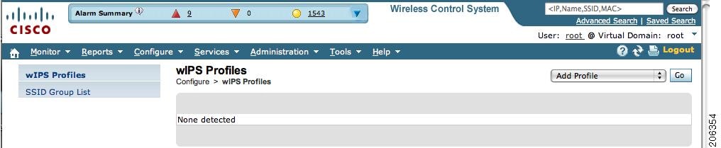
Step 3 ![]() From the Select a command drop-down list, choose Add Profile and click Go.
From the Select a command drop-down list, choose Add Profile and click Go.
Step 4 ![]() In the Profile Parameters dialog box, choose a profile template from the Copy From drop-down list (see Figure 6-7).
In the Profile Parameters dialog box, choose a profile template from the Copy From drop-down list (see Figure 6-7).
Note ![]() The Adaptive wIPS comes with a pre-defined set of profile templates from which customers can choose from or use as a basis for their own custom profiles. Each profile is tailored to either a specific business or application as are the specific alarms enabled on that profile.
The Adaptive wIPS comes with a pre-defined set of profile templates from which customers can choose from or use as a basis for their own custom profiles. Each profile is tailored to either a specific business or application as are the specific alarms enabled on that profile.
Note ![]() You cannot edit the default profile.
You cannot edit the default profile.
Note ![]() Ensure that the NMSP session is active to push the profile to the Controller.
Ensure that the NMSP session is active to push the profile to the Controller.
Figure 6-7 Profile Parameters Dialog Box
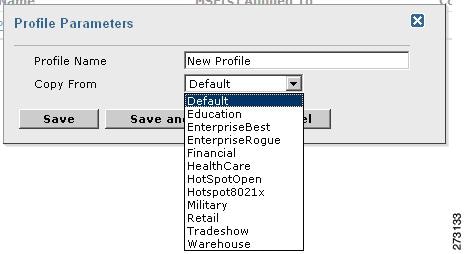
Step 5 ![]() After selecting a profile and entering a profile name, click Save and Edit.
After selecting a profile and entering a profile name, click Save and Edit.
Step 6 ![]() (Optional) Configure the SSIDs to Monitor (see Figure 6-8).
(Optional) Configure the SSIDs to Monitor (see Figure 6-8).
By default, the system monitors attacks launched against the local Wireless LAN Infrastructure (as defined by APs which have the same RF Group name). If the system should also be required to monitor attacks against another network, such as when deployed in an overlay deployment model, the SSID groups feature must be utilized.
Note ![]() If this step is not required, simply click Next.
If this step is not required, simply click Next.
Figure 6-8 SSID Groups Summary Pane
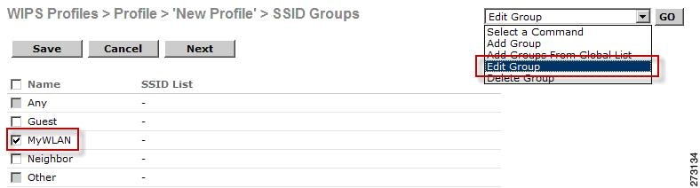
a. ![]() Select the MyWLAN check box and choose Edit Group from the drop-down list, then click Go.
Select the MyWLAN check box and choose Edit Group from the drop-down list, then click Go.
b. ![]() Enter SSIDs to Monitor.
Enter SSIDs to Monitor.
c. ![]() Enter the SSID name (separate multiple entries by a single space), and click Save (see Figure 6-9).
Enter the SSID name (separate multiple entries by a single space), and click Save (see Figure 6-9).
Figure 6-9 SSID Group Configuration Dialog Box
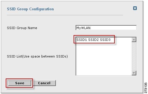
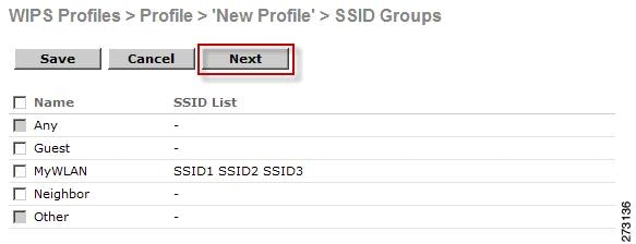
The SSID Groups page appears confirming the SSIDs are added successfully (see Figure 6-10).
Figure 6-10 New Profile > SSID Groups Page
d. ![]() Click Next.
Click Next.
The Select Policy and Policy Rules summary panes appear (see Figure 6-11).
Figure 6-11 Next > Select Policy Summary Pane
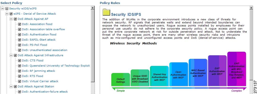
Note ![]() At the policy page (Figure 6-11), you can enable or disable attacks to be detected and reported. You can also edit specific thresholds for alarms and turn on forensics.
At the policy page (Figure 6-11), you can enable or disable attacks to be detected and reported. You can also edit specific thresholds for alarms and turn on forensics.
Step 7 ![]() To enable or disable attacks to be detected and reported, select the check box next to the specific attack type in question in the Select Policy pane.
To enable or disable attacks to be detected and reported, select the check box next to the specific attack type in question in the Select Policy pane.
Step 8 ![]() To edit the profile, click the name of the attack type (such as DoS: Association Flood).
To edit the profile, click the name of the attack type (such as DoS: Association Flood).
The configuration pane for that attack type appears in the right pane above the policy rule description (see Figure 6-12).
Figure 6-12 Policy Rules Pane
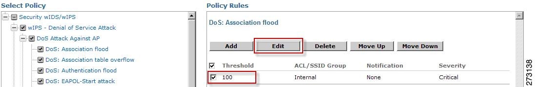
Step 9 ![]() To modify a policy rule do the following:
To modify a policy rule do the following:
a. ![]() In the Policy Rules pane, select the check box next to the policy rule, and click Edit.
In the Policy Rules pane, select the check box next to the policy rule, and click Edit.
The Policy Rule Configuration dialog box appears (see Figure 6-13).
Figure 6-13 Policy Rule Configuration Dialog Box
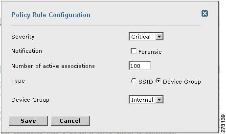
b. ![]() Choose the severity of the alarm.
Choose the severity of the alarm.
c. ![]() Select the Forensic check box if you want to capture packets for this alarm.
Select the Forensic check box if you want to capture packets for this alarm.
d. ![]() Modify the number of active associations, if desired. (This value varies by alarm type).
Modify the number of active associations, if desired. (This value varies by alarm type).
e. ![]() Select the type of WLAN infrastructure (SSID or Device Group) that the system will monitor for attacks.
Select the type of WLAN infrastructure (SSID or Device Group) that the system will monitor for attacks.
1. ![]() If you select SSID, continue with Step 10.
If you select SSID, continue with Step 10.
2. ![]() If you select Device Group, continue with Step 11.
If you select Device Group, continue with Step 11.
Note ![]() Device Group (Type) and Internal are the defaults. Internal indicates all access points within the same RF Group. Selecting SSID as the type, allows you to monitor a separate network which is typical of an overlay deployment.
Device Group (Type) and Internal are the defaults. Internal indicates all access points within the same RF Group. Selecting SSID as the type, allows you to monitor a separate network which is typical of an overlay deployment.
Step 10 ![]() (Optional, overlay deployments only) To add a policy rule for an SSID, do the following:
(Optional, overlay deployments only) To add a policy rule for an SSID, do the following:
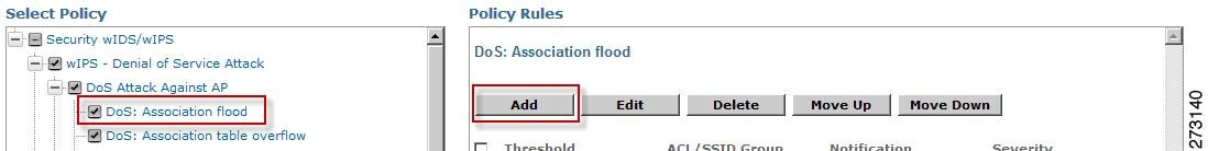
a. ![]() To add a policy rule, click Add (see Figure 6-14).
To add a policy rule, click Add (see Figure 6-14).
Figure 6-14 Adding a Policy Rule
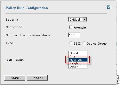
b. ![]() In the Policy Rule Configuration dialog box, select MyWLAN from the SSID Group list (see Figure 6-15).
In the Policy Rule Configuration dialog box, select MyWLAN from the SSID Group list (see Figure 6-15).
Note ![]() SSID is already selected as the type.
SSID is already selected as the type.
Figure 6-15 Policy Rule Configuration Dialog Box for SSIDs
c. ![]() Click Save after all changes are complete.
Click Save after all changes are complete.
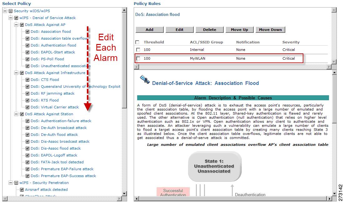
d. ![]() Modify each policy rule. Continue with Step 11 when all modifications are complete. (See Figure 6-16).
Modify each policy rule. Continue with Step 11 when all modifications are complete. (See Figure 6-16).
Note ![]() When you configure a system to monitor another WLAN infrastructure by SSID, changes must be made for each and every policy rule to monitor by SSID. You must create a policy rule under each separate alarm which defines the system to monitor attacks against the SSID Group created earlier.
When you configure a system to monitor another WLAN infrastructure by SSID, changes must be made for each and every policy rule to monitor by SSID. You must create a policy rule under each separate alarm which defines the system to monitor attacks against the SSID Group created earlier.
Figure 6-16 Edit Policy Rules for SSID Monitoring
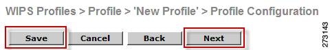
Step 11 ![]() In the Profile Configuration dialog box, click Save to save the Profile (SSID or Device Group). Click Next (see Figure 6-17).
In the Profile Configuration dialog box, click Save to save the Profile (SSID or Device Group). Click Next (see Figure 6-17).
Figure 6-17 Profile Configuration Dialog box
Step 12 ![]() Select the MSE/Controller combinations to apply the profile to and then click Apply (see Figure 6-18).
Select the MSE/Controller combinations to apply the profile to and then click Apply (see Figure 6-18).
Figure 6-18 Apply Profile Dialog Box

 Feedback