Cisco Catalyst 9800-CL Wireless Controller for Cloud Deployment Guide
Available Languages
Bias-Free Language
The documentation set for this product strives to use bias-free language. For the purposes of this documentation set, bias-free is defined as language that does not imply discrimination based on age, disability, gender, racial identity, ethnic identity, sexual orientation, socioeconomic status, and intersectionality. Exceptions may be present in the documentation due to language that is hardcoded in the user interfaces of the product software, language used based on RFP documentation, or language that is used by a referenced third-party product. Learn more about how Cisco is using Inclusive Language.
- US/Canada 800-553-2447
- Worldwide Support Phone Numbers
- All Tools
 Feedback
 Feedback
This document provides installation guidance for the virtual Cisco® Catalyst® 9800-CL Wireless Controller for Cloud with VMware ESXi, Linux KVM, Microsoft Hyper-V, and Cisco 5000 Series Enterprise Network Compute System (ENCS) Network Function Virtualization Infrastructure Software (NFVIS). The document:
● Provides an overview of the virtual deployment options
● Provides instructions for configuring and setting up the virtual wireless controller.
Supported hypervisor versions
For the supported hypervisor versions for the 9800-CL private cloud, please see the release notes for the required Cisco IOS® XE version here: https://www.cisco.com/c/en/us/support/wireless/catalyst-9800-series-wireless-controllers/products-release-notes-list.html
The table below shows an example of the Cisco IOS XE 17.6.x release train.
Table 1. Supported hypervisor versions for the 9800-CL private cloud running 17.6.x.
| Hypervisor |
Supported version |
| VMware ESXi |
ESXi vSphere: 6.0, 6.7, and 7.0 ESXi vCenter: 6.0, 6.5, 6.7, and 7.0 |
| KVM |
Red Hat Enterprise Linux: 7.6, 7.8, and 8.2 Ubuntu: 16.04 LTS, 18.04 LTS, 20.04.5 LTS |
| Microsoft Hyper-V1 |
Microsoft Windows Server: 2016 or 2019 (Standard, Enterprise, and Datacenter) Hyper-V Manager: 10.0.14393 |
| Cisco NFVIS |
Release 3.8.1 and 3.9.1 |
9800-CL virtual machine requirements
Scale and sizing suggest the minimum virtual resource requirements in the table below.
Table 2. Minimum virtual resource requirements for small, medium, and large configurations
|
|
Existing supported templates pre Cisco IOS XE Release 17.3 |
Templates added as part of Cisco IOS XE Release 17.3 |
||||
| Model configuration |
Small (Low throughput) |
Medium (Low throughput) |
Large (Low throughput) |
Small (High throughput) |
Medium (High throughput) |
Large (High throughput) |
| Minimum number of vCPUs1 (hyperthreading is not supported) |
4 |
6 |
10 |
7 |
9 |
13 |
| Minimum CPU allocation (MHz) |
4000 |
6000 |
10,000 |
4000 |
6000 |
10,000
|
| Minimum memory (GB) |
8 |
16 |
32 |
8 |
16 |
32 |
| Required storage2 (GB) |
16 |
16 |
16 |
16 |
16 |
16 |
| Virtual NICs (vNICs) (*) Third NIC is for High Availability |
2/(3)* |
2/(3)* |
2/(3)* |
2/(3)* |
2/(3)* |
2/(3)* |
| ESXi vNIC |
VMXNET3 |
VMXNET3 |
VMXNET3 |
VMXNET3 |
VMXNET3 |
VMXNET3 |
| Linux KVM vNIC |
OVS Linux bridge (brctl) |
OVS Linux bridge (brctl) |
OVS Linux bridge (brctl) |
OVS Linux bridge (brctl) |
OVS Linux bridge (brctl) |
OVS Linux bridge (brctl) |
| KVM NIC virtualization |
Virtio |
Virtio |
Virtio |
Virtio |
Virtio |
Virtio |
| Hyper-V vNIC |
NETVSC |
NETVSC |
NETVSC |
Not supported |
Not supported |
Not supported |
| Hyper-V NIC Virtualization |
VMBus |
VMBus |
VMBus |
Not supported |
Not supported |
Not supported |
| Maximum access points |
1000 |
3000 |
6000 |
1000 |
3000 |
6000 |
| Maximum clients supported |
10,000 |
32,000 |
64,000 |
10,000 |
32,000 |
64,000 |
| vMotion, vNIC teaming, Snapshot, DRS3 |
Supported |
Supported |
Supported |
Supported |
Supported |
Supported |
| VMware tools |
Not supported |
Not supported |
Not supported |
Not supported |
Not supported |
Not supported |
| Layer 2 link aggregation LAG4 |
Supported |
Supported |
Supported |
Supported |
Supported |
Supported |
9800-CL vCPU allocation
The 9800-CL vCPU allocation for control plane and data plane processes is shown in the table below.
Table 3. 9800-CL vCPU allocation for small, medium, and large configurations
|
|
|
CPU allocation |
|
| OVA template size |
Total number of vCPUs |
Control plane |
Data plane |
| Small |
4 |
2 |
2 |
| Small |
7 |
2 |
5 |
| Medium |
6 |
4 |
2 |
| Medium |
9 |
4 |
5 |
| Large |
10 |
8 |
2 |
| Large |
13 |
8 |
5 |
High Availability
High Availability (HA) is supported on the 9800-CL VM hosts using virtual redundant ports, in a stateful switchover (SSO) configuration as well as in an N+1 configuration.
9800-CL file format options
Catalyst 9800-CL deployment OVA template (OVA)
C9800-CL-universalk9.BLD_V***.ova
Catalyst 9800-CL deployment image
C9800-CL-universalk9.BLD_V***.iso
Catalyst 9800-CL upgrade and patches (bin)
C9800-CL-universalk9.upgrade***.bin
9800-CL network interface mappings
The Catalyst 9800-CL maps the GigabitEthernet network interfaces to the logical vNIC name assigned by the VM. The VM in turn maps the logical vNIC name to a physical MAC address.
When the Catalyst 9800-CL is booted for the first time, the router interfaces are mapped to the logical vNIC interfaces that were added when the VM was created. The figure below shows the relationship between the vNICs and the Catalyst 9800-CL interfaces.
By default, the 9800-CL comes with three network interfaces. Below is an example of interface mapping:
● GigabitEthernet1 > Device management interface: Map it to the out-of-band management network. This is the equivalent of the service port on the physical appliance.
● GigabitEthernet2 > Wireless management interface: Map it to the network to reach APs and services. Usually, this interface is a trunk to carry multiple VLANs.
● GigabitEthernet3 > High Availability interface: Map it to a separate network for peer-to-peer communication for HA SSO. This is the equivalent of the RP port. This port is not needed if HA SSO is not going to be configured.
Note: Do not connect two interfaces to a single network, as that may cause network loops. When a trunk port is used, you must either prune VLANs from vCenter or have the GigabitEthernet interfaces in a different vSwitch.

Mapping the vNICs to the Catalyst 9800-CL interfaces
The figure below shows an example of mapping the hypervisor physical port (vmnic2, connected to a switch trunk) to vSwitch0, as intended for the 9800-CL VM management interface, in ESXi. An optional interface intended for use in the redundant HA configuration (vmnic3) is named RP and mapped to vSwitch3.
Note: When testing two 9800-CL controllers in the same Cisco UCS® server and using RP ports for HA, it is not necessary to connect the physical RP mapped physical adapters at all. However, if active and standby 9800-CL controllers are on separate hypervisors, the RP mapped physical ports need to be connected to the network and must be Layer 2 adjacent and reachable by each other.

Mapping the hypervisor to the VM management interface in ESXi
By default, a hypervisor vSwitch is configured to reject promiscuous mode. For 9800-CL, besides the above mapping to the hypervisor interfaces, promiscuous mode needs to be set to “accept" in order for the vSwitch to carry traffic to the 9800-CL.
Secure Boot
Starting with Cisco IOS XE 17.6.1, Secure Boot deployments of the 9800-CL VM hosts are supported.
For information on enabling Secure Boot, go to https://www.cisco.com/c/en/us/td/docs/wireless/controller/9800/9800-cloud/installation/b-c9800-cl-install-guide/controller_overview.html#concept_z44_fcm_cdb
Deploying the 9800-CL using VMware ESXi
Design considerations with VMware VM operations
When deploying VMware VM operations such as vMotion, DRS, Snapshot and vNIC teaming, there are a few design considerations to take into account.
Using SR-IOV interfaces
If SR-IOV interfaces are deployed with the 9800-CL, none of the VM operations are supported. This is due to how SR-IOV works within ESXi as documented at https://docs.vmware.com/en/VMware-vSphere/7.0/com.vmware.vsphere.networking.doc/GUID-E8E8D7B2-FE67-4B4F-921F-C3D6D7223869.html
Snapshot
When taking a snapshot, there is a chance the controller might crash. To avoid this, we recommend configuring RAID0 on the Cisco UCS for both SSD and HDD.
Note: Cloning from snapshots is not supported.
vMotion
When deploying vMotion on the 9800-CL in standalone mode, vMotion will work without caveats.
However, when the 9800-CL is deployed in HA SSO, there are a few considerations to take into account.
● Do not run vMotion on both the active and standby VMs at the same time. In the time it takes for the active and standby to move to the new hardware resource, the 9800-CL may be seen as going down.
● When using vMotion with 9800-CL in HA SSO, there will be an extended data outage if no packets originate from WLC. This is due to a limitation in ESXi for Virtual Guest Tagging (VGT mode). As a workaround, a continuous ping will need to be initiated from the 9800-CL to update the MAC address in the right port on the physical switch. For more details, see https://kb.vmware.com/s/article/2113783?lang=en_US.
NSX Support
● VMware NSX-T is not supported with the Cisco Catalyst 9800-CL Wireless Controller.
● When NSX is enabled on the host where the C9800-CL is located, all interfaces are integrated into NSX by default. To avoid the automatic integration of the C9800-CL VM into NSX, you must exclude the C9800-CL VM from NSX.
In a NIC teamed environment where multiple uplinks are configured for a virtual switch and a port channel LACP is not configured on the physical switch, the vSwitch will receive a multicast or broadcast packet from the physical network on each vSwitch uplink in the NIC team. All traffic received by the vSwitch will be forwarded to the virtual portgroup in promiscuous mode so the virtual machine guest OS will receive multiple multicast or broadcast packets. To prevent this issue, you must enable the /Net/ReversePathFwdCheckPromisc setting in VMware.
Deploying the 9800-CL using the OVA
The provided OVA file package can be used to deploy the Cisco wireless controller to the VM. The OVA package includes an OVF file that contains a default VM configuration based on the Cisco IOS XE release and the supported hypervisor.
The following considerations apply when deploying the OVA package to the VM:
● The single OVA package creates a VM with options for three types of virtual wireless controllers, small, medium, and large. Selecting a profile specifies the required virtual CPU and memory. The hard disk requirement will be the same—16 GB—for any wireless controller type. We do not recommend changing the virtual CPU and memory configuration after deployment.
● When deploying using the OVA template, the VM will bootstrap with three interfaces: one is for out-of-band management, one is for wireless management (usually mapped to a trunk interface on the switch side), and the third is for HA to connect to the SSO peer.
● The installation process can be monitored using the virtual VGA console or the console on the virtual serial port. A virtual serial port is optional and can be added after deploying the OVA. At first customer shipment (FCS) the serial console port is not supported for large-scale deployments. If the serial port is required, please see Appendix B: Adding a virtual serial port in ESXi.
Using the ESXi embedded web GUI
VMware ESXi provides a direct deployment of the virtual Catalyst 9800-CL wireless controller without bootstrap customization (see Deploying the OVA to ESXi with vCenter Server).
Perform the following steps in the VMware GUI.
Step 1. Log in to the VMware embedded GUI at https://ESXi_Host_IP.
Step 2. From the Host page, choose Create/Register VM.

Step 3. In the New virtual machine wizard, select Deploy a virtual machine from an OVF or OVA file. Click Next.

Step 4. Enter a name for the 9800-CL VM and select the OVA file that will be deployed. Click Next.

Step 5. Select the datastore for the VM’s configuration files and virtual disks. Click Next.

Step 6. In the Network mappings section, allocate one port group for each of the required network interfaces.

Note: Please refer to Appendix A: Creating a port group in ESXi for steps to configure the port groups for the VM.
Note: SR-IOV interfaces are high-performance interfaces possible in certain Intel® NIC cards. Refer to Appendix C: Enabling and using the SR-IOV NIC in ESXi to see how to enable and attach them to the 9800-CL.
Step 7. In the Deployment type section, select the desired hardware configuration (AP and client scale) template from the drop-down menu.
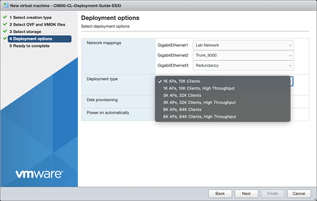
Step 8. The rest of the settings in the Disk provisioning and Power on automatically sections can be left at their defaults. Click Next.

Note: If using the virtual serial port, uncheck the box for Power on automatically, and refer to Appendix B: Adding a virtual serial port in ESXi (optional).
Step 9. Confirm the configured settings. Click Finish to deploy the OVA.


Step 10. Once the VM is finished deploying, select the 9800-CL VM and open the console.

Step 11. Go to the Configuring the 9800-CL section.
Deploying the OVA to ESXi with vCenter Server
VMware vCenter has a flow similar to that of standalone ESXi, except for the ability to customize and bootstrap the virtual wireless controller with login and network information so that the Command-Line Interface (CLI) is not needed at all.
Step 1. Log in to vCenter and choose Launch vSphere Web Client (HTML5).

Step 2. Select Actions à Deploy OVF Template.

Step 3. Enter the URL where the OVA file can be downloaded or select Local file and choose a file. Click Next.

Step 4. Enter a name and select a location for the VM. Click Next.

Step 5. Select which ESXi host to deploy the 9800-CL on. Click Next.

Step 6. Verify the details of the template. Click Next.

Step 7. Select the configuration (AP and client scale) template. Click Next.

Step 8. Select the storage. Click Next.

Step 9. Map the virtual network interface(s) and click Next.

Step 10. As was mentioned earlier, vCenter deployment provides an option to customize or bootstrap the Catalyst 9800-CL wireless controller with a hostname, network configuration, and login. Go through the steps to provide any necessary information using the provided template, and click Next.

Note: When specifying the device management interface, choose the interface mapped to the out-of-band management network. It will be configured as a Layer 3 routed interface with the IP address provided in this step. The network entered in step 2.4 is the remote network from which the 9800-CL will be managed. This will create a static route to that specified network.
Note: When deploying the OVA via vCenter, the configuration bootstrap will always get applied, so “wr erase” and “reload” will not bring the box to the default configuration. If the deployment does not require bootstrapping or if the 9800-CL needs to be reset to the factory default, please do not power on the 9800-CL after deploying, and refer to the steps in Appendix E: Resetting the 9800-CL to the factory default.
Step 11. Finally, review the configuration data. Click Finish to deploy the 9800-CL in vCenter.

Step 12. Select Power on after deployment.
Note: If you are removing the configuration bootstrap, please do not power on the 9800-CL after deploying and refer to the steps in Appendix E: Resetting the 9800-CL to the factory default.

Step 13. Go to the Configuring the 9800-CL section.
Deploying the 9800-CL using the ISO
Step 1. Copy the 9800-CL ISO file into the datastore.
Step 2. Create a new virtual machine and choose the OS family/version as suggested below.
● Compatibility: Required ESXi version
● Guest OS family: Other
● Guest OS version: Other (64-bit)

Step 3. Select the datastore for deploying the 9800-CL.

Step 4. Choose the CPU, memory, and hard disk size depending on the deployment requirements. Refer to the virtual machine requirement and scale shown earlier in Table 2.

Step 5. Add the required network adapters and select the port groups needed. Ensure that the network adapter type is VMXNET 3.

Step 6. Ensure that the CD/DVD drive is set to Datastore ISO File and that the Status is checked for Connect at power on. Select the ISO file for the 9800-CL. Click Next.

Step 7. Review the configuration and click Finish. Start the VM.
Step 8. After ISO installation, walk through the initial setup wizard and configure SVIs, wireless interface, trustpoint, etc. (Review the previous sections, as these will be the same.)
Step 9. Go to the Configuring the 9800-CL section.
Deploying the 9800-CL on Linux KVM
The virtual Cisco Catalyst 9800-CL Wireless Controller for Cloud can be deployed in Linux KVM using an ISO file (downloaded from the Cisco website), with support for the following distribution:
● Red Hat Enterprise Linux (RHEL) 7.1 or higher
● Ubuntu 16.04 LTS or higher
This guide will not cover every aspect of Linux or KVM components, only the general set of instructions needed to deploy a virtual wireless controller on KVM.
Scale for the virtual 9800-CL on Linux KVM
Table 4. Minimum virtual resource requirements for small, medium, and large configurations
|
|
Existing supported templates pre Cisco IOS XE Release 17.3 |
Templates added as part of Cisco IOS XE Release 17.3 |
||||
| Model configuration |
Small (Low throughput) |
Medium (Low throughput) |
Large1 (Low throughput) |
Small (High throughput) |
Medium (High throughput) |
Large1 (High throughput) |
| Minimum number of vCPUs |
4 |
6 |
10 |
7 |
9 |
13 |
| Minimum CPU allocation (MHz) |
4000 |
6000 |
10,000 |
4000 |
6000 |
10,000 |
| Minimum memory (GB) |
8 |
16 |
32 |
8 |
16 |
32 |
| Required storage (GB) |
16 |
16 |
16 |
16 |
16 |
16 |
| Virtual NICs (vNICs) (*) Third NIC is for High Availability |
2/(3)* |
2/(3)* |
2/(3)* |
2/(3)* |
2/(3)* |
2/(3)* |
| Linux KVM vNIC |
OVS Linux bridge (brctl) |
OVS Linux bridge (brctl) |
OVS Linux bridge (brctl) |
OVS Linux bridge (brctl) |
OVS Linux bridge (brctl) |
OVS Linux bridge (brctl) |
| NIC virtualization |
Virtio |
Virtio |
Virtio |
Virtio |
Virtio |
Virtio |
| Maximum access points |
1000 |
3000 |
6000 |
1000 |
3000 |
6000 |
| Maximum clients supported |
10,000 |
32,000 |
64,000 |
10,000 |
32,000 |
64,000 |
| Layer 2 LAG, SR-IOV |
Supported |
Supported |
Supported |
Supported |
Supported |
Supported |
Prerequisites before installing KVM
To run KVM, a processor that supports hardware virtualization is required. Intel and AMD both have developed extensions for their processors, deemed, respectively, Intel VT-x (code name Vanderpool) and AMD-V (code name Pacifica).
To see if the processor supports one of these extensions, issue the following command and review the output:
egrep -c '(vmx|svm)' /proc/cpuinfo
If the result is 0, it means the CPU doesn't support hardware virtualization.
If it is 1 or more, it does support hardware virtualization, but virtualization needs to be enabled in the BIOS.
Required packages for KVM
The following KVM packages are required for installation:
· Qemu-kvm
· Qemu-utils
· Uml-utilities
· Bridge-utils
· Socat
· Kvm
· Libvirt-bin
· Virtinst
The following are Ubuntu sample commands to install the packages:
| # apt-get install qemu-kvm qemu-utils uml-utilities bridge-utils socat # apt-get install kvm libvirt-bin virtinst |
Use the following command to install the packages in RHEL:
| # yum install kvm libvirt |
Networking options vary within Linux. Effectively, KVM supports the following:
Linux bridge
OVS switch
The following are sample network settings, where br0 and br1 can be mapped to the virtual wireless controller interface(s):
| [root@localhost ~]# vim /etc/network/interfaces
interfaces(5) file used by ifup(8) and ifdown(8) auto lo iface lo inet loopback
auto br0 iface br0 inet static address 10.104.170.99 netmask 255.255.255.0 network 10.104.170.0 broadcast 10.104.170.255 #gateway 10.104.170.1 #up route add default gw 10.104.170.1 # dns-* options are implemented by the resolvconf package, if installed bridge_ports eth0 bridge_stp off bridge_fd 0 bridge_maxwait 0 dns-nameservers 72.163.128.140
auto br1 iface br1 inet static address 9.11.124.44 network 9.11.124.0 netmask 255.255.255.0 bridge_ports eth1 bridge_stp off bridge_fd 0 bridge_maxwait 0 |
For how to configure the SR-IOV interfaces for KVM, see Appendix D: Enabling and using the SR-IOV NIC in KVM.
| sudo virt-install --virt-type=kvm --name C9800_sriov_3-18 --ram 16384 --vcpus=9 --hvm --cdrom=/home/C9800-CL-universalk9.BLD_POLARIS_DEV_LATEST_20200318_062819-serial.iso --network none --host-device=pci_0000_18_06_0 --host-device=pci_0000_18_06_1 --graphics vnc --disk path=/var/lib/libvirt/images/C9800_sriov_3-18.qcow2,size=8,bus=virtio,format=qcow2 |
Verify this on the 9800-CL console after launching:
| C9800> en C9800#show platform software vnic-if interface-mapping ------------------------------------------------------------- Interface Name Driver Name Mac Addr ------------------------------------------------------------- GigabitEthernet2 net_i40e_vf 3cfd.fede.ccbd GigabitEthernet1 net_i40e_vf 3cfd.fede.ccbc ------------------------------------------------------------- |
Attaching to an existing VM using the CLI
Adding the PCI device number:

causes the address domain, bus, slot, and function to be derived from the PCI BDF by the script in step 1.
| # virsh edit <VM name> # virsh edit <name of virtual machine> # virsh dump <name of virtual machine> <domain> … <devices> … <hostdev mode=’subsystem’ type=’pci’ managed=’yes’> <source> <address domain=’0x0000’ bus=’0x18’ slot=’0x06’ function=’0x0’/> </source> </hostdev> … </devices> … </domain> |
Attaching to the 9800-CL using the Virtual Machine Manager
In the Virtual Machine Manager (virt-manager), use the Add Hardware button to add the PCI host device. Navigate to the NIC and choose the VF that needs to be attached to the VM.

Once the PCI is added to the VM, start the VM.
Table 5. Verified and recommended software versions for SR-IOV
| Guest OS |
NIC |
Driver version |
Firmware |
| KVM RedHat Version 7.5 |
Intel x710 |
I40e 2.10.19.82 |
7.10 |
| KVM RedHat Version 7.4 |
Ciscoized x710 |
I40e 2.10.19.82 |
7.0 |
Creating the Catalyst 9800-CL VM using the virt-manager GUI tool
Once the Linux KVM requirement is met, the packages have been installed, and networking has been configured, download the ISO from Cisco for use with the virt-manager. This GUI tool is the easiest method for deploying the virtual 9800-CL wireless controller. The following examples are based on Ubuntu/Gnome as a desktop environment.
Step 1. Start Virtual Machine Manager and choose Create a new virtual machine. Select Local install media (ISO image) and click Forward.

Step 2. Browse and select the Catalyst 9800-CL ISO file.

Step 3. Using the AP and client scale guide in Table 4, set the CPU and memory requirements. For example, four CPUs and 8 GB RAM are recommended for small deployments with 1000 APs and 6000 clients. Click Forward.

Step 4. Create a disk of 8 GB (standard for all deployment sizes). Click Forward.

Step 5. Provide a name for the VM and select Customize configuration before install. (Note: This setting is important.) Click Forward.

The default is a single interface at the time of VM creation. This can be used as any of the functional virtual 9800-CL interfaces, for example, the wireless management interface. However, if an additional interface (or serial port) is needed, use the Add New Virtual Hardware tool.
Step 6. Go to Add New Virtual Hardware > Network interface. Map each of the vNICs to the target bridge interface defined in the Linux network configuration.

Step 7. For each vNIC, set the Device model to virtio. Click Finish.

Step 8. A virtual serial console also exists for KVM. Simply add the virtual hardware, select Serial, Host = 127.0.0.1 (local host), and the port number (user-defined), and check Use Telnet. Click Finish.

Below is an example of a console using Telnet to connect to the KVM hypervisor at a user-defined port.

Step 9. Next, click Begin Installation. The VM will boot and progress through the installation process.

Step 10. Progress can be monitored through the KVM VM console.

Step 11. Go to the Configuring the 9800-CL section.
Deploying the 9800-CL on Microsoft Hyper-V
Starting with Cisco IOS XE Release 17.1.1, the virtual Cisco Catalyst 9800-CL Wireless Controller for Cloud can be deployed in Microsoft Hyper-V, using an ISO file (downloaded from the Cisco website). Hyper-V is supported on the following Windows installations:
● Windows Server 2016 or later – Standard, Enterprise, and Datacenter edition
● Hyper-V Manager – Version 10.0.14393 or later
This guide will not cover every aspect of Hyper-V and Windows components, only the general set of instructions needed to deploy a virtual wireless controller on Hyper-V.
For more information on getting started with Hyper-V, see https://docs.microsoft.com/en-us/virtualization/hyper-v-on-windows/about/
Scale for the Virtual 9800-CL on Hyper-V
Table 6. Minimum virtual resource requirements for small, medium, and large configurations on Hyper-V
|
|
Existing supported templates pre Cisco IOS XE Release 17.3 |
||
| Model configuration |
Small (Low throughput) |
Medium (Low throughput) |
Large (Low throughput) |
| Minimum number of vCPUs |
4 |
6 |
10 |
| Minimum CPU allocation (MHz) |
4000 |
6000 |
10,000 |
| Minimum memory (GB) |
8 |
16 |
32 |
| Required storage (GB) |
16 |
16 |
16 |
| Virtual NICs (vNICs) (*) Third NIC is for High Availability |
2/(3)* |
2/(3)* |
2/(3)* |
| Hyper-V vNIC |
NETVSC |
NETVSC |
NETVSC |
| NIC virtualization |
VMBus |
VMBus |
VMBus |
| Maximum access points |
1000 |
3000 |
6000 |
| Maximum clients supported |
10,000 |
32,000 |
64,000 |
Catalyst 9800-CL deployment image – Requires Cisco IOS XE Release 17.1.1 or higher
C9800-CL-universalk9.***.iso
Catalyst 9800-CL upgrade and patches (bin)
C9800-CL-universalk9.***.bin
If Hyper-V is not already installed, follow the steps here to install it: https://docs.microsoft.com/en-us/windows-server/virtualization/hyper-v/hyper-v-on-windows-server
Hyper-V supports mapping the physical network interfaces to a virtual switch. The virtual switch is used by the VM network adapter to send traffic to the rest of the network.
The easiest method to create the virtual switch is done using the Hyper-V Manager GUI tool.
Step 1. Open Hyper-V Manager by going to Control Panel > System & Security > Administrative Tools.

Step 2. In the Actions pane, click Virtual Switch Manager.

Step 3. In the New virtual network switch section, select an External virtual switch. Click Create Virtual Switch.

Step 4. Set the name of the virtual switch. In the drop-down menu, select the physical NIC that will be connected to the virtual switch, and, if the Windows host uses the NIC to connect to the network, check Allow management operating system to share this network adapter. If the Windows host requires VLAN ID, check Enable virtual LAN identification for management operating system and enter the VLAN ID. Click Apply.

Step 5. Repeat steps 3 and 4 for any other physical NICs.
Creating the Catalyst 9800-CL VM using the Hyper-V Manager GUI tool
Download the ISO from Cisco for use with the Hyper-V Manager. This GUI tool is the easiest method for deploying the virtual 9800-CL wireless controller.
Step 1. Open Hyper-V Manager by going to Control Panel > System & Security > Administrative Tools.
Step 2. In the Actions pane, click New > Virtual Machine.

Step 3. Provide a name for the VM and specify a location to store it. Click Next.

Step 4. Specify either generation of the VM. This can be either Generation 1 or Generation 2. Click Next.
Note: The generation cannot be changed after the VM has been created.

Step 5. Set the memory requirements of the VM based on the AP and client scale in Table 6. The example below is for small deployments with 1000 APs and 6000 clients. Click Next.

Step 6. Specify the network connection for the included network adapter, or this can be done later. This network adapter will correspond to GigabitEthernet1 within the 9800-CL VM.

Step 7. Create a new virtual disk with a size of 16 GB (standard for all deployment sizes). Click Next.

Step 8. To boot from the ISO file for the 9800-CL, select Install an operating system from a bootable CD/DVD-ROM and enter the location for the required ISO file of the 9800-CL image.

Step 9. Click Finish to complete the VM creation.

Step 10. Navigate to the settings page for the VM. Right-click the 9800-CL VM and select settings.

Step 11. Go to the Processor section. Set the number of processors based on the AP and client scale in Table 6. The example below shows four virtual processors for a small deployment with 1000 APs and 6000 clients.

Step 12. The default is a single network adapter at the time of VM creation. This can be used as any of the functional virtual 9800-CL interfaces, such as the wireless management interface.
However, if additional adapters are required, you will need to use either PowerShell or the Hyper-V GUI, depending on whether the traffic for the network adapters will be tagged or untagged or trunked. These options are described below.
The network adapter will have traffic that is untagged or tagged with a single VLAN ID (GigabitEthernet1 and GigabitEthernet3):
Go to Add Hardware and select Network Adapter. Click Add.

Repeat for any additional network adapters.
For each network adapter, go to the required Network Adapter section. Select the required Virtual switch. If VLAN tagging is required, check Enable virtual LAN identification and enter the required VLAN ID. Click OK.

The network adapter needs to be configured as a trunk port (normally for GigabitEthernet2):
Open the PowerShell application as administrator.
Enter the following commands:
| Add-VMNetworkAdapter -VMName <VM Name> -SwitchName <Virtual Switch Name> Name <Network Adapter Name> Set-VMNetworkAdapterVlan -VMName <VM Name> -VMNetworkAdapterName <Network Adapter Name> -Trunk -AllowedVlanIdList <VLAN Range> -NativeVlanId <VLAN ID> |
Example: Creating the network adapter for GigabitEthernet2 on the 9800-CL. It is configured as a trunk port with a native VLAN ID of 0 that allows traffic with VLAN IDs between 1 and 4000.

To verify the VLAN settings for the VM adapters, type the command:
| Get-VMNetworkAdapterVlan -VMName <VM Name> |
Example:

Step 13. Start the 9800-CL VM by right clicking the VM and selecting Start.

Step 14. The installation progress can be monitored through the Hyper-V console.

Step 15. Go to the Configuring the 9800-CL section.
Creating the Catalyst 9800-CL VM in Hyper-V with the CLI using PowerShell
In addition to the Hyper-V Manager GUI, the 9800-CL can be deployed using PowerShell. This can help in automating the deployment process of 9800-CL VMs.
Step 1. Open a PowerShell window as Administrator.
Step 2. Create the VM using the following command:
New-VM -Name <VMName> -Path <VMPath> -MemoryStartupBytes <Startup Memory> -NewVHDPath <VHD Path> -NewVHDSizeBytes <VHD(X) size> -SwitchName <VM Switch Name> -Generation <VM Gen (1 or 2)>
Example:
| PS C:\Windows\system32> New-VM -Name C9800-CL-CLI -Path "C:\ProgramData\Microsoft\Windows\Hyper-V\Virtual Machines" -MemoryStartupBytes 8GB -NewVHDPath "C:\Users\Public\Documents\Hyper-V\Virtual hard disks\C9800-CL-CLI.vhdx" -NewVHDSizeBytes 17179869184 -SwitchName "Lab Switch" -Generation 1
Name State CPUUsage(%) MemoryAssigned(M) Uptime Status Version ---- ----- ----------- ----------------- ------ ------ ------- C9800-CL-CLI Off 0 0 00:00:00 Operating normally 9.0 |
Step 3. Set the number of processors required for the VM deployment.
Set-VM -Name <VMName> -ProcessorCount <Number of Processors>
Example:
| PS C:\Windows\system32> Set-VM -Name C9800-CL-CLI -ProcessorCount 4 PS C:\Windows\system32> |
Step 4. Map the virtual DVD drive to the ISO image path.
| Set-VMDvdDrive -VMName <VMName> -Path <ISO Image Path> |
Example:
| PS C:\Windows\system32> Set-VMDvdDrive -VMName C9800-CL-CLI -Path "C:\Users\netadmin\Downloads\C9800-CL-universalk9.17.06.02.iso" PS C:\Windows\system32> |
Step 5. If needed, create additional network interfaces.
Add-VMNetworkAdapter -VMName <VM Name> -SwitchName <Virtual Switch Name> Name <Network Adapter Name>
If the interface needs to be tagged with a single VLAN ID, enter the following command to set the interface as an access port with traffic tagged with the configured VLAN.
Set-VMNetworkAdapterVlan -VMName <VM Name> -Access -VlanId <VLAN ID>
Example:
| Create access port PS C:\Windows\system32> Set-VMNetworkAdapterVlan -VMName C9800-CL-CLI -VMNetworkAdapterName "Network Adapter" -Access -VlanID 125 |
If the interface needs to be configured as a trunk port, enter the following command:
Set-VMNetworkAdapterVlan -VMName <VM Name> -VMNetworkAdapterName <Network Adapter Name> -Trunk -AllowedVlanIdList <VLAN Range> -NativeVlanId <VLAN ID>
Example:
| PS C:\Windows\system32> Add-VMNetworkAdapter -VMName C9800-CL-CLI -SwitchName "Lab Switch" -Name "Gigabit2" PS C:\Windows\system32> Set-VMNetworkAdapterVlan -VMName C9800-CL-CLI -VMNetworkAdapterName "Gigabit2" -Trunk -AllowedVlanIdList "1-4000" -NativeVlanID 0 PS C:\Windows\system32> Get-VMNetworkAdapterVlan -VMName C9800-CL-CLI VMName VMNetworkAdapterName Mode VlanList ------ -------------------- ---- -------- C9800-CL-CLI Network Adapter Access 125 C9800-CL-CLI Gigabit2 Trunk 0,1-4000 |
To verify the interfaces, enter the following command:
Get-VMNetworkAdapterVlan -VMName <VM Name>
Example:
| PS C:\Windows\system32> Get-VMNetworkAdapterVlan -VMName C9800-CL-CLI VMName VMNetworkAdapterName Mode VlanList ------ -------------------- ---- -------- C9800-CL-CLI Network Adapter Access 125 C9800-CL-CLI Gigabit2 Trunk 0,1-4000 |
Step 6. Start the 9800-CL VM.
Start-VM <VM Name>
Example:
| PS C:\Windows\system32> Start-VM C9800-CL-CLI PS C:\Windows\system32> Get-VM Name State CPUUsage(%) MemoryAssigned(M) Uptime Status Version ---- ----- ----------- ----------------- ------ ------ ------- C9800-CL-CLI Running 16 8192 00:00:12.7660000 Operating normally 9.0 |
Step 7. Go to the Configuring the 9800-CL section.
Deploying the 9800-CL on the Cisco ENCS NFVIS platform
Overview of Cisco NFVIS software
Cisco Enterprise Network Function Virtualization Infrastructure Software (NFVIS) is Linux-based infrastructure software designed to help service providers and enterprises dynamically deploy virtualized network functions, such as a virtual router, firewall, and WAN acceleration, on a supported Cisco device. The addition of a physical device for every network function is not required; automated provisioning and centralized management can be used.
The Cisco Enterprise NFVIS solution helps convert critical network functions into software, making it possible to deploy network services in minutes across dispersed locations. It provides a fully integrated platform that can run on top of a diverse network of both virtual and physical devices.
The Cisco 5400 Enterprise Network Compute System (ENCS) combines routing, switching, storage, processing, and a host of other computing and networking activities into a compact 1-Rack-Unit (1RU) box. This high-performance unit achieves this goal by providing the infrastructure to deploy virtualized network functions and acting as a server that addresses processing, workload, and storage challenges.
The virtual Catalyst 9800-CL Wireless Controller for Cloud can be deployed on a Cisco ENCS NFVIS platform using an ISO file or tar.gz (download from the Cisco website).
The NFVIS software version should be higher than 3.8. If the NFVIS software version is lower than 3.8, it should be upgraded to any version higher than 3.8. To upgrade the NFVIS software, refer to the “Upgrading Cisco NFVIS” section in the following document:
https://www.cisco.com/c/en/us/td/docs/routers/nfvis/config/3-10-1/nfvis-config-guide-3-10-1.html
Scale for the virtual 9800-CL on Cisco ENCS NFVIS
The virtual Catalyst 9800-CL Wireless Controller for Cloud on the ENCS NFVIS platform supports:
● 1000 access points
● 10,000 wireless clients
It needs four CPUs, 8 GB of RAM, 8 GB of storage space, and three vNICs. (The third vNIC is for HA/SSO.)
Note: Other sizes (medium and large) for the 9800-CL are not supported on the Cisco ENCS NFVIS platform.
Log in to the WebUI of NFVIS with the username (admin) and the password that was set up.
Uploading the image on NFVIS
Follow the procedure below to upload an image to NFVIS (a screenshot highlighting the procedure described is given below for reference).
Step 1. Select VM Life Cycle > Image Repository.
Step 2. Select the Image Registration tab, click Drop Files or Click, and select the 9800-CL virtual image file for NFVIS from a local machine to be uploaded (for example, C9800-CL-universalk9.16.10.01e.tar.gz).
Step 3. Click Start to upload the image.
After the image is uploaded, NFVIS creates respective profiles and registers the image. The file can be found listed in the Images section on the same page.

Creating a network
Follow the procedure below to create a network.
Step 1. Select VM Life Cycle > Networking.

Step 2. Click the + (Create) icon next to Networks & Bridges.

Step 3. Populate the fields with values (Network, Mode, VLAN, Bridge, and Interface).

Note: Create separate network interfaces for the wireless management network, service interface, and HA, and map them to separate bridge interfaces. Each bridge interface maps to a physical interface.
Example:
● A wireless management network named mgmt-intf with the Mode set to Trunk, carrying multiple VLANs, mapped to a bridge interface named mgmt-br tied to physical interface GE0-0.
● An HA network named ha-intf with the Mode set to access, mapped to a bridge interface named ha-br tied to physical interface GE0-1.
Deploying the 9800-CL virtual controller on NFVIS
Follow the procedure below to deploy the 9800-CL virtual controller on NFVIS.
Step 1. Select VM Life Cycle > Deploy.

Step 2. From the VM Deployment window, drag and drop the controller icon to the pane below and map it to the desired networks as required. In the VM Details area, enter a name for the 9800-CL controller. Select the image and profile from the drop-down menu.
Note: Only 1000 APs and 10,000 clients are supported.

Step 3. Map the network interfaces and click Deploy.

Step 4. Once deployed, check the 9800-CL’s status in VM Life Cycle > Manage > VM Status.

Step 5. Click the console symbol next to the VM name to open the console to the 9800-CL virtual controller that is deployed.

Step 6. Go to the Configuring the 9800-CL section.
Enable serial console access
Step 1. Issue the following command on the 9800-CL VM:
| C9800_SJC_1# configure terminal C9800-SJC_1(config)# platform console serial |
Step 2. SSH to the management interface of ENCS to access the 9800-CL console.
| nfvis# show system deployments NAME ID STATE ------------------- vWLC 2 running
nfvis# vmConsole ? Possible completions: VM name; "show system deployments" command shows list of VM names.
nfvis# vmConsole <VM name > |
Viewing VM resource allocation
Follow the procedure below to view the VM resource allocations.
Step 1. From NFVIS, select VM Life Cycle > Resource Allocation.
This opens up the VM CPU Allocation tab, which displays the overall CPU allocations.

Step 2. Click the VM Memory Allocation tab.
This tab shows the overall memory allocations.

Step 3. Click the VM Disk Allocation tab.
This tab shows the overall disk allocations.

Note: VM must be redeployed to increase the disk space from 8 GB to 16 GB (as required from the Cisco IOS XE Amsterdam 17.3).
Viewing VM statistics
Follow the procedure below to view the VM resource utilization.
Step 1. From NFVIS, select VM Life Cycle > VM Monitoring.
This opens up the VM CPU Utilization tab, which displays the overall CPU utilization per VM. Click the other tabs — Memory Utilization, vNIC Utilization, and Disk Utilization — to view the utilization of the resource.

9800-CL DAY 0 CLI configuration setup wizard
For Cisco IOS XE Release 17.4.1 and above, the 9800-CL provides a DAY 0 CLI wizard. To access the CLI, connect to the VGA console. Within the wizard, configurations such as Device Management interface, Wireless Management interface, deployment mode, and self-signed certificate for AP join will be created. After going through the wizard, the controller will generate the new configuration and apply it.
Note: If the DAY 0 WebUI wizard is preferred, please see the Configure the basic 9800-CL settings section first.
Example of DAY 0 CLI configuration wizard
| --- System Configuration Dialog ---
Would you like to enter the initial configuration dialog? [yes/no]: yes
At any point you may enter a question mark ‘?’ for help. Use ctrl-c to abort configuration dialog at any prompt. Default settings are in square brackets ‘[]’.
This is a Wireless LAN Controller (WLC) setup wizard. This wizard gives the option to configure a device management interface, aka Service Port. If a separate Service Port is not desired, the device can also be managed using the same interface which is used for wireless management. For such a case, please select [no] in the prompt below
Setup device management interface (aka Service Port)? [yes]: yes Select interface to be used for device management 1. GigabitEthernet1 [Up] 2. GigabitEthernet2 [Up] 3. GigabitEthernet3 [Up] Choose the interface to config [1]: 1
... Truncating Output ...
[0] Go to the IOS command prompt without saving this config. [1] Return back to the setup without saving this config. [2] Save this configuration to nvram and exit.
Enter your selection: 2 Building configuration... [OK] Use the enabled mode 'configure' command to modify this configuration.
Building configuration... [OK] |
Configure the basic 9800-CL settings
Let’s create the minimal configuration to connect to the WebUI of the 9800-CL and use the DAY 0 guided flow to get the controller fully operational. This will establish basic IP connectivity and user login on the 9800-CL.
Before 17.4.1, DAY 0 assumes that the box has two separate virtual interfaces (one for device management and one for wireless management and client traffic) and that the first login happens on the device management (out-of-band) interface. The wireless management interface is configured via the DAY 0 guided flow. If using a different setup (for example, if you are using only a single interface), see the previous section or go to Configuring the 9800-CL via the CLI: Skipping the DAY 0 guided flow section.
Connect to the CLI via the VGA console and follow these steps for the basic configuration:
Step 1. Terminate the configuration wizard (this is the general Cisco IOS CLI wizard, and it’s not specific for wireless).
| Would you like to enter the initial configuration dialog? [yes/no]: no Would you like to terminate autoinstall? [yes]: yes |
Step 2. Optionally, set the hostname:
| WLC(config)# hostname C9800 |
Step 3. Add login credentials, using the following command:
| C9800(config)# username <name> privilege 15 password <yourpwd> |
Step 4. Add an IP address on the device management interface. The example assumes GigabitEthernet1 is mapped to the out-of-band/device management network during VM bootstrap:
| C9800(config)# interface GigabitEthernet1 C9800(config-if)# no switchport C9800(config-if)# ip address <Management IP> <Management Subnet> |
Step 5. Add the route to the remote network from which the 9800-CL will be managed.
| C9800(config)# ip route <Remote Network Address> <Remote Network Subnet> <Gateway> |
Note: With an ESXi direct host, no default bootstrap configuration is passed to the instance. If one is desired, you must enter the following configurations manually (these are automatically configured if using vCenter):
| netconf-yang ip http server ip http secure-server line vty 0 4 transport input telnet ssh login local |
From a computer, verify that the computer can ping the 9800-CL.
9800-CL DAY 0 WebUI configuration setup wizard
Since the box has never been configured, the WebUI will redirect to the DAY 0 page. To skip the DAY 0. WebUI, [lease see the Configuring the 9800-CL via the CLI: Skipping the DAY 0 guided flow section.
To simplify the bootstrap process of the Catalyst 9800-CL wireless controller, the DAY 0 wizard will appear after a virtual instance is deployed, with network connectivity but without any other wireless configuration.
Step 1. Connect to the DAY 0 GUI using https://< Management IP>.

To log in, use the username and password credentials given during the 9800-CL instance creation described in the previous sections.
Step 2. Once you are logged in, the 9800-CL presents a simplified configuration flow to set the basic parameters and have the controller fully operational. On the first page, enter the required information.

These settings are Deployment Mode, Country, Date, Time, NTP Servers (optional), and AAA Servers (optional).
Note: For Deployment Mode, the available options are Standalone or Active/Standby if configuring HA SSO.
Step 3. Enter the wireless management interface configuration.

Note: Only an interface that is different from the one used to access the GUI can be selected. In the example above, only GigabitEthernet2 or GigabitEthernet3 can be selected, as GigabitEthernet1 is used to access the GUI.
Step 4. Configure the interface by choosing the VLAN, the IP address, and the default gateway. This will automatically configure the:
● Interface as a trunk port
● Switch Virtual Interface (SVI) for wireless management
● Default gateway.
Click Next.
Step 5. On the next page, add a WLAN (optional) so that clients can connect. In this example, the PSK dialog is shown.

Step 6. On the next page, set some basic RF parameters and the AP certificate.

A trustpoint is essentially a certificate authority that is trusted implicitly. A trustpoint certificate is a self-signed certificate, hence the name “trustpoint,” since it does not rely on the trust of anyone else or another party. A trustpoint is needed for an AP to join the 9800-CL. It can be automatically generated during DAY 0. Otherwise, if the Generate Certificate is toggled to No, a certificate authority will have to be configured at DAY 1 for APs to join.
Click Summary to review the configuration, and then click Finish. The configuration and trustpoint will be pushed to the device and the user will be logged out. The 9800-CL controller will not reboot, but it will take about 60 seconds to prompt you to log in again. Enter the same credentials.
This time it will skip the DAY 0 page, since the box already has an initial configuration, and redirect to the main dashboard for the DAY 1 configuration.
Configuring the 9800-CL via the CLI: Skipping the DAY 0 guided flow
If two separate virtual interfaces for device management and wireless management are not needed, create the DAY 0 configuration via the CLI and then access the GUI for the DAY 1 configuration. However, if separate interfaces are necessary, please follow the steps in the “Configure the basic 9800-CL settings” section first.
Follow the steps below to configure the 9800-CL with a wireless management interface and skip the DAY 0 flow.
This example assumes that GigabitEthernet2 is connected to a trunk interface on the switch and multiple VLANs will be configured with a dedicated one for the Wireless Management Interface (WMI). Also, in this example, VLAN 122 will be used for the WMI.
Step 1. Access the CLI via the VGA/monitor console of ESXi.
Step 2. Terminate the configuration wizard (this wizard is not specific for the wireless controller).
| Would you like to enter the initial configuration dialog? [yes/no]: no Would you like to terminate autoinstall? [yes]: yes |
Step 3. Optionally, set the hostname:
| WLC(config)# hostname C9800 |
Step 4. Enter the config mode and add login credentials using the following command:
| C9800(config)# username <name> privilege 15 password <yourpwd> |
Step 5. Configure the VLAN for the wireless management interface.
| C9800# configure terminal Enter configuration commands, one per line. End with CNTL/Z. C9800(config)# vlan 122 C9800(config-vlan)# name wireless_management |
Step 6. Configure the SVI for the wireless management interface; for example:
| C9800(config)# interface vlan 122 C9800(config-if)# ip address 172.20.229.21 255.255.255.192 C9800(config-if)# no shutdown |
Step 7. Configure the interface GigabitEthernet2 as the trunk:
| C9800(config-if)# interface GigabitEthernet2 C9800(config-if)# switchport mode trunk C9800(config-if)# switchport trunk allowed vlan 122 C9800(config-if)# shut C9800(config-if)# no shut |
Step 8. Configure a default route (or a more specific route) to reach the box:
| C9800(config-if)# ip route 0.0.0.0 0.0.0.0 172.20.229.1 |
Step 9. Configure the AP country domain. This configuration is what will trigger the GUI to skip the DAY 0 flow, as the 9800-CL needs a country code to be operational:
| C9800(config)# wireless country ? AE United Arab Emirates AL Albania AR Argentina ... US United States UY Uruguay VE Venezuela VN Vietnam ZA South Africa |
Step 10. A certificate is needed for the AP to join the virtual 9800-CL. This can be created automatically via the DAY 0 flow or manually using the following commands.
a. Specify the interface to be the wireless management interface:
| C9800(config)# wireless management interface vlan 122 |
b. In exec mode, issue the following command:
| C9800# wireless config vwlc-ssc key-size 2048 signature-algo sha256 password 0 <pwd> |
Note: Ensure that the gateway for the WMI is reachable from the 9800-CL.
Step 11. Verify certificate installation:
| C9800# show wireless management trustpoint |
Note: The certificate/trustpoint configuration can be skipped, but APs will not be able to join. This can be configured via the GUI by importing the desired certificate.
Step 12. Verify that the WMI can be pinged, and enter https://<Management IP>. Use the credentials entered earlier. Since the box has a country code configured, the GUI will skip the DAY 0 page and go directly to the main dashboard for the DAY 1 configuration.
Once the 9800-CL can be reached successfully from the network, access the main dashboard to continue the DAY 1 and DAY 2 operations.
Step 1. Access the 9800-CL WebUI using https://<Management IP>. The username and password will be what was provided either during the initial configuration or during the OVA installation with vCenter.

Appendix A: Creating a port group in ESXi
To create a port group, a virtual switch needs to be created. Follow the steps outlined here to create a virtual switch: https://docs.vmware.com/en/VMware-vSphere/6.7/com.vmware.vsphere.html.hostclient.doc/GUID-6BF5281C-F8EF-4F26-8285-52EB5999D687.html
Step 1. Go to the WebUI of the ESXi host.
Step 2. Go to Networking > Port groups and click Add port group.

Step 3. In the Add port group window, set the:
● Name
● VLAN ID
◦ The VLAN ID should be the same VLAN ID used for rest of the network. This would be the case for the management and redundancy interfaces, which would be on their own respective VLANs.
◦ For the data port, the port group should be set to be a trunk port. To do this, set the VLAN ID to 4095.
● Virtual switch
● Security
◦ Both Promiscuous mode and Forged Transmits need to be set to Accept on the port group where the 9800-CL is connected. This is needed for both trunk and nontrunk connections. These security settings can be restricted to the single port group where the 9800-CL is connected, and as long as the VLANs are available only on this port group, the settings will not affect other VMs connected to other port groups. This is recommended, as setting Promiscuous mode to Accept will result in flooding traffic to all the other VMs on the same VLAN.

Step 4. Click Add to save the settings.
Step 5. Repeat for all required port groups.
To create a port group, a virtual switch needs to be created. Follow the steps outlined here to create a virtual switch: https://docs.vmware.com/en/VMware-vSphere/6.7/com.vmware.vsphere.networking.doc/GUID-DAF824CD-104D-4ED7-8BA3-D769DF688CEB.html
Step 1. Go to the vSphere Web Client.
Step 2. Select the required ESXi host.

Step 3. Go to the Configure tab and select Networking > Virtual switches. Click ADD NETWORKING.

Step 4. In the Add Networking window, set the connection type as Virtual Machine Port Group for a Standard Switch. Click Next.

Step 5. Select the required vSwitch for the port group. Click Next.

Step 6. Set the Network label and VLAN ID for the port group. Click Next.

Note: The VLAN ID should be the same VLAN ID used for rest of the network. This would be the case for the management and redundancy interfaces, which would be on their own respective VLANs. For the data port, the port group should be set to be a trunk port. To do this, set the VLAN ID to 4095.
Step 7. Review the settings and click Finish.

Step 8. To change the security settings of the port group, click the … icon for the newly created port group. Choose Edit Settings.

Step 9. In the Security section, check the override boxes for Promiscuous mode and Forged transmits. Set both values to Accept. Click OK.

Note: Both Promiscuous mode and Forged Transmits need to be set to Accept on the port group where the 9800-CL is connected. This is needed both for trunk and nontrunk connections. These security settings can be restricted to the single port group where the 9800-CL is connected, and as long as the VLANs are available only on this port group, the settings will not affect other VMs connected to other port groups. This is recommended, as setting Promiscuous mode to Accept will result in flooding traffic to all the other VMs on the same VLAN.
Step 10. Repeat for all required port groups.
Appendix B: Adding a virtual serial port in ESXi
Adding a virtual serial port allows an administrator to connect to the virtual wireless controller like accessing a physical appliance’s serial console.
Step 1. In the Edit settings window for 9800-CL, click Add other device. Select Serial port.

Step 2. In the New Serial Port settings:
a. Select Use network, as Telnet will be used to connect to the ESXi network address and custom port assignment.
b. For Direction, select Server.
c. Enter the port URI to connect to.
d. Click Save.
| telnet://<ESXi IP address>:<port> |
Note: The ESXi IP address can be omitted (for example, telnet://:<port>). In this case, the IP address of the ESXi host the device is hosted on will used.

Step 3. To allow for computers to access the serial port of the VM, go to Networking > Firewall rules. Select VM serial port connected over network.

Step 4. Click Actions and then click Enable.

Step 5. Click the Play icon to power on the VM and bring up the VGA console simultaneously.

Step 6. If this is the first boot after creating the VM, select the Serial Console boot option to change the default console output to the serial port. This will be a one-time action. Proceed to step 7.
Note: If this step is missed, the console output can be changed to the serial port via the 9800-CL CLI. Please see step 6.

Step 7. If vWLC Virtual (VGA) Console was selected, enter the followings commands in the 9800-CL CLI.
| C9800> enable C9800# configure terminal C9800(config)# platform console serial |
The mode will be available on the next reload.
Step 8. Once the 9800-CL has booted with the serial console option selected (or platform serial mode enabled), connect to the console of the 9800-CL by using Telnet to the ESXi and assigned port.
![]()

Step 9. To revert back to using the VGA console, enter the following commands and reload the
9800-CL.
| C9800> enable C9800# configure terminal C9800(config)# no platform console serial C9800(config)# platform console virtual |
The mode will be available on the next reload.
Appendix C: Enabling and using the SR-IOV NIC in ESXi
SR-IOV (single-root I/O virtualization) introduction
SR-IOV provides the ability to partition a single physical PCI resource into virtual PCI functions which can then be injected into a VM. These network Virtual Functions (VFs) of SR-IOV improve north-south network performance by allowing traffic to bypass the host machine’s network stack.
● Each virtual machine is directly assigned and given access to the physical resources (VFs) by the hypervisor (VMM).
● VMs load up specific drivers to support SR-IOV.
● The VM boots up and probes its PCIe config space to see what devices it has.
● VMM tells that it has a VF attached and indicates the HW registers for VFs to the NIC driver in the VM.

Reference: Intel SR-IOV architecture
Enabling SR-IOV on the C9800-CL on ESXi
Step 1. Enable SR-IOV on the network adapter.

Step 2. Enable and configure the virtual functions on the adapter.
Note: Ethernet Server Adapter X710 supports up to 32 VFs per port. Creating one VF per port gives the maximum performance. Each VF would represent a NIC.

Step 3. Reboot the ESXi host and the SR-IOV configurations will take effect.
Step 4. Create a new virtual switch without any physical NICs attached to it.

Step 5. Create a new port group with the settings below and attach it to the newly created vSwitch. The settings below are for the WMI, which will act as a trunk port.
● VLAN ID: 4095
● Promiscuous Mode: Accept
● MAC Address Changes: Accept
● Forged Transmits: Accept

Step 6. Edit the VM and reserve all the guest memory for the VM, which is necessary for SR-IOV. For the 9800-CL, this will be 8192 MB.

Step 7. Edit the VM, remove the network port already attached, and add a new network adapter with the following settings:
● Port group: Set to the newly created port group
● Adapter Type: SR-IOV passthrough
● Physical function: Required Physical NIC with SR-IOV enabled
● Guest OS MTU Change: Allow

Step 8. Save the configuration and reboot the VM.
Step 9. In the Security settings, verify that the trust settings are updated correctly on the NIC.
https://kb.vmware.com/s/varticle/74909
vSwitch security policy is not persistent when SR-IOV is enabled. To work around this, SSH to ESXi.
Step 10. Use the following command to verify that the NIC is trusted and spoof check is disabled.
| esxcli intnet sriovnic vf get -n <nic> |
Example:
| esxcli intnet sriovnic vf get -n vmnic2 VF ID Trusted Spoof Check ----- ------- ----------- 0 true false |
If the trust parameters are not set correctly
Step 1. Stop the C9800-CL VM at the boot prompt.
| GNU GRUB version 0.97 (638K lower / 3143552K upper memory +-------------------------------------------------------------------+ | vWLC – packages.conf | vWLC – GOLDEN IMAGE |
Step 2. Use the CLI to set the trust parameters using the following command:
| esxcli intnet sriovnic vf set -t on -s off -v <vf num> -n <nic> |
● -t sets the trust mode
● -s sets the spoof check
For firmware and driver versions prior to and including firmware version 7.0 and driver version 1.8.6, the above two steps are always needed on VM reboot.
Verified and recommended software versions
| Guest OS |
NIC |
Driver version |
Firmware |
Notes |
| VMware Version 6.5 |
Intel x710 |
I40en 1.10.6 Plugin version 1.4.1 |
7.10 |
|
| VMware Version 6.5 |
Ciscoized x710 |
I40en 1.8.6 Plugin version 1.4.1 |
7.0 |
7.0 firmware and 1.8.6 driver have a trust mode persistence issue across VM reload. Issue will be fixed in subsequent firmware and driver versions. |
Appendix D: Enabling and using the SR-IOV NIC in KVM
Step 1. Install the latest drivers for the NIC.
The Ethernet and driver versions can be verified using the following command:
| # ethtool -i <interface name> |
Example output:

The script below can print all the Ethernet information followed by the driver versions and the SR-IOV VF names.

Example output from script below:
| #!/bin/bash # Copy this script to a .sh file and execute echo "Listing all the PCI NIC Interfaces " echo -------------------------------------------------------- lspci | grep -i eth
NIC_DIR="/sys/class/net" for i in $( ls $NIC_DIR) ; do if [ -d "${NIC_DIR}/$i/device" -a ! -L "${NIC_DIR}/$i/device/physfn" ]; then declare -a VF_PCI_BDF declare -a VF_INTERFACE k=0 for j in $( ls "${NIC_DIR}/$i/device" ) ; do if [[ "$j" == "virtfn"* ]]; then VF_PCI=$( readlink "${NIC_DIR}/$i/device/$j" | cut -d '/' -f2 ) VF_PCI_BDF[$k]=$VF_PCI #get the interface name for the VF at this PCI Address for iface in $( ls $NIC_DIR ); do link_dir=$( readlink ${NIC_DIR}/$iface ) if [[ "$link_dir" == *"$VF_PCI"* ]]; then VF_INTERFACE[$k]=$iface fi done ((k++)) fi done NUM_VFs=${#VF_PCI_BDF[@]} if [[ $NUM_VFs -gt 0 ]]; then echo +-+-+-+-+-+-+-+-+-+-+-+-+-+-+-+-+-+-+-+-+-+-+-+-+-+-+-+-+-+-+-+-+-+-+ echo "Driver Versions" ethtool -i $i echo -------------------------------------------------------------------- #get the PF Device Description PF_PCI=$( readlink "${NIC_DIR}/$i/device" | cut -d '/' -f4 ) PF_VENDOR=$( lspci -vmmks $PF_PCI | grep ^Vendor | cut -f2) PF_NAME=$( lspci -vmmks $PF_PCI | grep ^Device | cut -f2). echo "Virtual Functions on $PF_VENDOR $PF_NAME ($i):" echo -e "PCI BDF\t\tInterface" echo -e "=======\t\t=========" for (( l = 0; l < $NUM_VFs; l++ )) ; do echo -e "${VF_PCI_BDF[$l]}\t${VF_INTERFACE[$l]}" done unset VF_PCI_BDF unset VF_INTERFACE echo " " fi fi done |
References for the firmware downloads can be found in the links below.
Firmware for Intel NIC
https://downloadcenter.intel.com/product/82947/Intel-Ethernet-Controller-X710-Series
Driver for Intel and Cisco NIC
Firmware for Cisco NIC
Step 2. Verify that the Intel VT-D support is enabled on the Linux Kernel.
Do this by running the command dmesg | grep -e DMAR -e IOMMU
The output should show that the IOMMU is enabled, as shown in the example below

If the VT-D support is not enabled:
1. Activate Intel VT-d in the kernel by adding the intel_iommu=on and iommu=pt parameters to the end of the GRUB_CMDLINX_LINUX line, within the quotes, in the /etc/sysconfig/grub file.
2. Regenerate /etc/grub2.cfg by running:
| grub2-mkconfig -o /etc/grub2.cfg |
3. Reboot the system to enable the changes. The system is now capable of PCI device assignment.
Step 3. Configure SR-IOV VFs on the NIC.
In step 1, if the VF is not seen in the output of the script, enable it using the following commands:
Configure VF on the NIC:
| # echo 1 > /sys/class/net/enp129s0f0/device/sriov_numvfs |
Create one VF per port for maximum performance.
Configure spoofcheck, trust mode, and MAC using the commands below:
| # ip link set dev enp129s0f0 vf 0 trust on # ip link set enp129s0f0 vf 0 spoofchk off # ip link set enp129s0f0 vf 0 mac 3c:fd:fe:de:cc:bc |
Verify the settings using the command below:
| # ip link show <nic name> |
Example:
| [root@localhost ~]# ip link show enp129s0f0 6: enp129s0f0: <BROADCAST,MULTICAST> mtu 1500 qdisc noop state DOWN mode DEFAULT group default qlen 1000 link/ether 3c:fd:fe:de:01:bc brd ff:ff:ff:ff:ff:ff vf 0 MAC 3c:fd:fe:de:cc:bc, spoof checking off, link-state auto, trust on |
Step 4. SR-IOV setting persistence:
SR-IOV configurations configured in the above way are not persistent across the reboots. To fix this, the above configuration can be run as a service that is auto enabled on host reboots.
1. Create a bash script with the commands to be persisted, for example, in /usr/bin/sriov-config. Write the script in /usr/bin/sriov-config :
| #!/bin/sh echo 1 > /sys/class/net/enp129s0f0/device/sriov_numvfs ip link set dev enp129s0f0 vf 0 trust on ip link set enp129s0f0 vf 0 spoofchk off ip link set enp129s0f0 vf 0 mac 3c:fd:fe:de:cc:bc |
2. Repeat the above for all VFs.
3. Provide execute permission for the script:
| # chmod 777 /usr/bin/sriov-config |
4. Create the system service: Define a new systemd service to be executed at the end of boot. This service executes the bash script which has the required SR-IOV commands, as shown in step 1.
Note: "ExecStart=/usr/bin/sriov-config" given below executes the script.
To create the system service, make a new file "sriov.service" in /usr/lib/systemd/system with the following content:
| [Unit] Description=SR-IOV configuration After=rc-local.service Before=getty.target [Service] Type=oneshot ExecStart=/usr/bin/sriov-config [Install] WantedBy=multi-user.target |
Step 5. Enable and start the service using:
| # systemctl --now enable sriov.service |
This command will start the service immediately and also ensures that the service runs every time the host reboots.
Reference: The SR-IOV configuration for KVM is explained at:
Step 6. Attach the SR-IOV to the C9800-CL:
Attaching to a new VM using the command line
Add the PCI VF devices using the host device command. Using the script from step 1, note the PCI BDF number and use that to attach the devices.

Appendix E: Resetting the 9800-CL to the factory default
All 9800-CL deployments except those using the OVA file with vCenter
Step 1. To reset the 9800-CL instance to the factory default, use the following commands:
| C9800-CL# wr erase Erasing the nvram filesystem will remove all configuration files! Continue? [confirm] [OK] Erase of nvram: complete |
Step 2. Reload the box and enter no at the Save configuration prompt.
| C9800-CL# reload System configuration has been modified. Save? [yes/no]: no Reload command is being issued on Active unit, this will reload the whole stack Proceed with reload? [confirm] |
Step 3. Then press Enter at the second prompt. The box will reload and come up with the default configuration.
9800-CL deployments using the OVA file with vCenter
If the 9800-CL was deployed using the OVA file via ESXi vCenter, there is a configuration bootstrap that will always get applied, so “wr erase” and “reload” will not bring the box to the default configuration.
Step 1. Power off the 9800-CL VM.
Step 2. Go to Edit Settings.

Step 3. Under CD/DVD drive 2, click the X icon to delete. This stores the bootstrap configuration configured during deployment. Deleting it enables the 9800-CL to reset to the factory defaults.

Step 4. Click OK to save the changes.
Step 5. Follow the steps outlined at the beginning of this appendix to reset the 9800-CL to factory defaults.
Appendix F: 9800-CL CLI reference
| C9800-CL# show platform software vnic-if interface-mapping ------------------------------------------------------------- Interface Name Driver Name Mac Addr ------------------------------------------------------------- GigabitEthernet1 net_vmxnet3 0050.5693.1d6e |
| C9800-CL# show int gig 1 GigabitEthernet1 is up, line protocol is up Hardware is CSR vNIC, address is 0050.5693.1d6e (bia 0050.5693.1d6e) |
| C9800-CL# show ip int brief Interface IP-Address OK? Method Status Protocol GigabitEthernet1 unassigned YES unset up up Capwap1 unassigned YES unset up up Capwap2 unassigned YES unset up up Capwap3 unassigned YES unset up up Vlan1 unassigned YES NVRAM administratively down down Vlan10 10.10.1.2 YES NVRAM up up Vlan118 172.20.228.41 YES NVRAM up up |