Scope, Objectives, and Expectations
The following topics are covered under this chapter:
- The New AP 1532
- Getting Started with the AP 1532
- Flexible Antenna-Port Configuration
- Daisy Chaining with AP 1532
- Preferred Parent
- Bridge Group Name
- Deployment Modes
- Autonomous Software
- Range and Capacity Calculator
- Design and Planning with the 1532 Access Point
- Troubleshooting
The New AP 1532
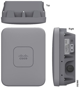
The AP 1532 series is an ultra low-profile outdoor access point. This AP has two models, an internal antenna model and an external antenna model.
AP 1532I
- Two radios (2.4 GHz and 5 GHz)
- UPoE and DC power (48V)
- Console Port
- 2.3 kg weight
- LTE and WIMAX Signal Rejection (2.1/2.3 GHz; 30 dB; 2.5 GHz; 35 dB)
- 23 x 17 x 10 cm (9 x 7 x 4”); < 3.0 Liters
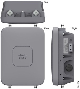
AP 1532E
- Two radios (2.4 GHz and 5 GHz)
- PoE+ (802.3at). and DC power (48V)
- Console Port
- 2.5 kg weight
- LTE and WIMAX Signal Rejection (2.1/2.3 GHz; 30 dB; 2.5 GHz; 35 dB)
- Autonomous Bridging Functionality (Replacement for the 1310 and 1410 product lines)
- 26 x 17 x 10 cm (10 x 7 x 4”); 3.0 Liters
Getting Started with the AP 1532
The AP 1532 Hardware Components
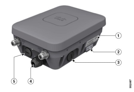
| 1 | SN Label | 4 | PoE-In; WAN Port |
| 2 | Ground | 5 | LAN Port |
| 3 | DC Power 48 VDC |
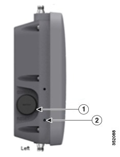
| 1 | Console/Reset | 2 | Solar Shield Screw Holes |
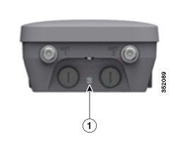
| 1 | LED |
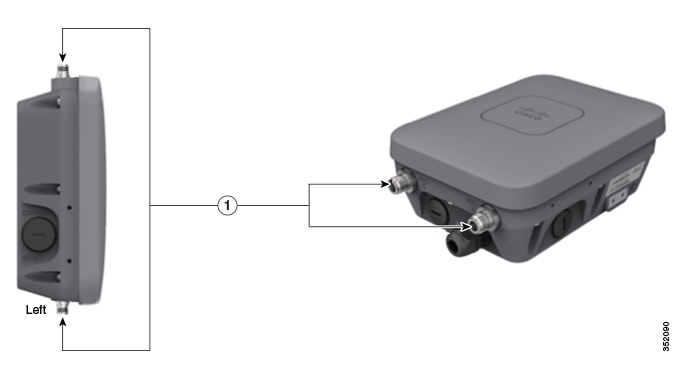
| 1 | Flexible Antenna Port (N Type) Connectors |
 Note | The Flexible Antenna Port Connectors are only present on the 1532E. |
Antenna Options for the AP 1532E
| Product ID | Freq. Band | Gain | Type | Required Quantity |
|---|---|---|---|---|
| AIR-ANT2547V-N | 2.4 / 5 GHz | 4 / 7 dBi | Omnidirectional | 2 |
| AIR-ANT2547VG-N | 2.4 / 5 GHz | 4 / 7 dBi | Omnidirectional | 2 |
| AIR-ANT2588P3M-N= | 2.4 / 5 GHz | 8 / 8 dBi | Directional 120x30° | 1 |
| AIR-ANT2450V-N= | 2.4 GHz | 5 dBi | Omnidirectional | 2 |
| AIR-ANT2480V-N= | 2.4 GHz | 8 dBi | Omnidirectional | 2 |
| AIR-ANT2413P2M-N= | 2.4 GHz | 13 dBi | Directional 30x30° | 1 |
| AIR-ANT5180V-N= | 5 GHz | 8 dBi | Omnidirectional | 2 |
| AIR-ANT5114P2M-N= | 5 GHz | 14 dBi | Directional 30x30° | 1 |
AP 1532 Power Supplies
| Model | Configuration | Regulatory Domain | Switch Power | AIR-PWRINJ1500-2= | AIR-PWRINJ4= | AC/DC Power Adapter AIR-PWRADPT-1530= |
|---|---|---|---|---|---|---|
| 1532I | 3x3:3 (2.4 GHz)
2x3:2 (5 GHz) |
A, D, K, N, Q, T, Z | UPoE | √ | √ | |
| one Tx disabled*
2x3:2 (2.4 GHz) 2x3:2 (5 GHz) |
A, D, K, N, Q, T, Z | 802.3at PoE+ | N/A | √ | N/A | |
| 3x3:3 (2.4 GHz)
2x3:2 (5 GHz) |
C, E, F, H, M, R, S | 802.3at PoE+ | √ | √ | √ | |
| 1532E | 2x2:2 (2.4 GHz)
2x2:2 (5 GHz) |
all | 802.3at PoE+ | √ | √ | √ |
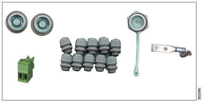
AP 1532 Accessories
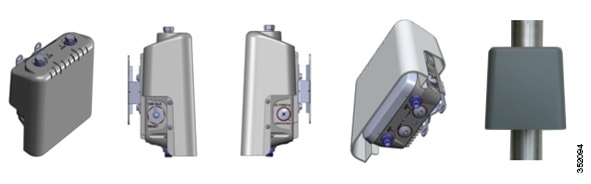
- AIR-ACC1530-PMK1 (=) -
Wall/Pole mount bracket, available as an orderable option or as an add-on.
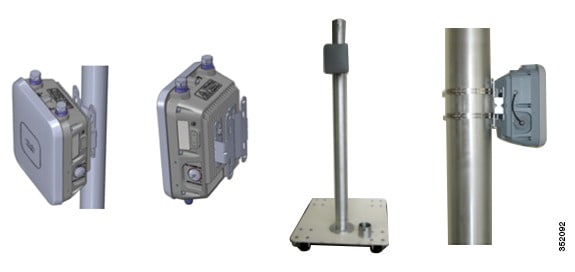
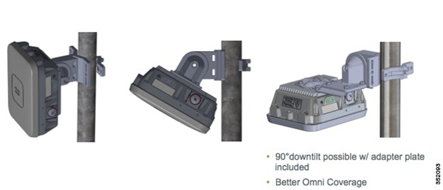
- AIR-ACC1530-PMK2= -
Wall/Pole mount bracket with tilt mechanism, orderable as an add-on.
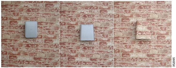
- AP1532 Solar Shield Cover
(AIR-ACC1530-CVR=) - Cover / Solar Shield for 1532, orderable as an add-on.
This accessory is paintable.
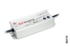
- AIR-PWRADPT-1530= - AC/DC
power adapter, orderable as an add-on.
- AIR-ACC1530-KIT1= - Extra
cable glands, power connector, ground lug, and Ethernet caps.
Note | For more details please visit the 1532 Hardware Installation guide: http://www.cisco.com/en/US/docs/wireless/access_point/1530/installation/guide/1530hig.html |
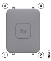
Flexible Antenna-Port Configuration
There are two terms that are used when referring to Antenna Band Mode Configurations:
- Dual Antenna Band Mode – The bottom two ports, port 1 and port 2, are used for dual band 2.4 GHz/5 GHz Dual Radiating Element (DRE) antennas.
- Single Antenna Band Mode – The top two ports, port 3 and port 4, are used for 5 GHz Single Radiating Element (SRE) antennas while the bottom two ports, port 1 and port 2, are used for 2.4 GHz SRE antennas.
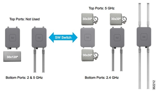
Please note that Antenna Band Mode is only available on the 1532E model, with external antennas; the 1532I has an internal antenna and does not require additional antennas.
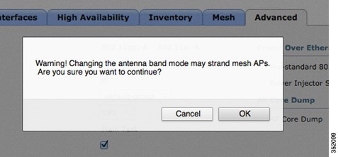
Configuring Antenna Band Mode from the WLC GUI
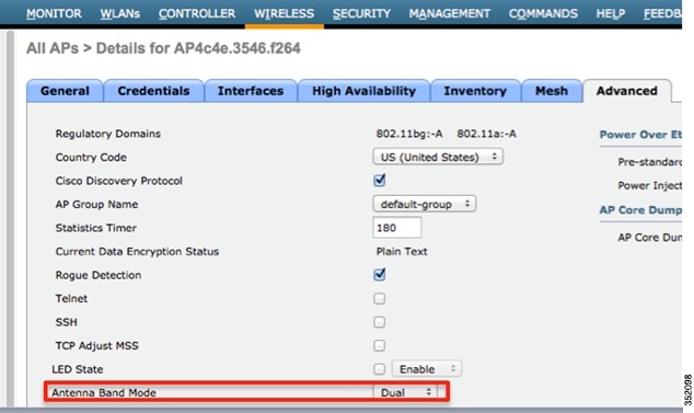
Note | Misconfiguring the Antenna Band Mode can strand a mesh AP, please make sure your physical antennas are properly configured before changing the Antenna Band Mode. A warning message will be displayed to confirm the changes. |
Configuring Antenna Band Mode from the WLC CLI
(Cisco Controller) >config ap antenna-band-mode <single|dual> <ap_name>
(Cisco Controller) >show ap config general <AP_NAME>
Antenna Band Mode ............................... Dual
Configuring Antenna Band Mode from the AP CLI
AP#capwap ap ant-band-mode <dual/single>
Daisy Chaining with AP 1532
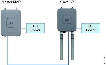
One of the key features of the 1532 access point is the ability to “daisy chain” access points while they are operating as Mesh APs (MAPs). By “daisy chaining” MAPs, customers can either operate the access points as a serial backhaul, allowing different channels for uplink and downlink access thus improving backhaul bandwidth, or to extend universal access across a mesh network. Extending universal access allows a customer to connect a local mode or flexconnect mode 1532 access point to the Ethernet port of a MAP, thus extending the network to provide better client access. These features will be explained in greater detail in the following sections.
There are two roles of a daisy-chained access point, the Master AP and Slave AP. The Master AP must be configured as a Mesh AP (MAP), it is also recommended to set a preferred-parent and Bridge-group name. The Slave AP can either be configured as a Bridge Mode Root AP if used for serial backhaul or as a Local/Flexconnect Mode AP if used for extended universal access.
Requirements for Daisy Chaining AP 1532s
- The uplink daisy-chained AP is considered the Master AP, the connected AP is considered the Slave AP.
- The Master AP must be configured as Mesh AP (MAP).
- The Slave AP must be configured either as Bridge Mode Root AP or a local/Flexconnect AP, but not as a Mesh AP. If the Slave AP is configured as a MAP there is risk of a layer 2 bridging loop.
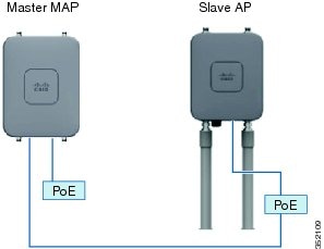
- The connecting Ethernet cable must go from the LAN port of the Master AP to the PoE-in port of the Slave AP.
- There should be a preferred parent set for each daisy-chained mesh hop. The Master MAP will have a preferred parent assigned.
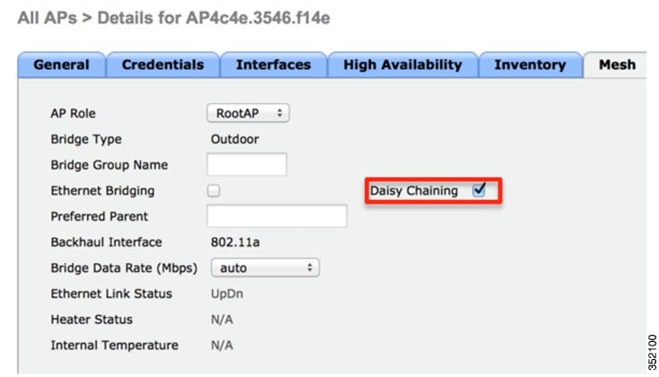
- Daisy-chaining must be enabled on the Slave APs when they are configured as RAPs, either via WLC GUI, WLC CLI, or AP CLI.
- Directional Antennas should be used when creating a daisy chain; these should be used to guide the mesh tree formation to the customer’s needs.
- There can only be one slave AP per Master AP. One Master AP to multiple Slave APs is not supported.
- The Slave AP should be connected directly to the LAN Ethernet port of the Master AP. There should be no other layer 2 switching devices in-between.
- APs 1532I and 1532E can be used interchangeably as the master and the slave AP.
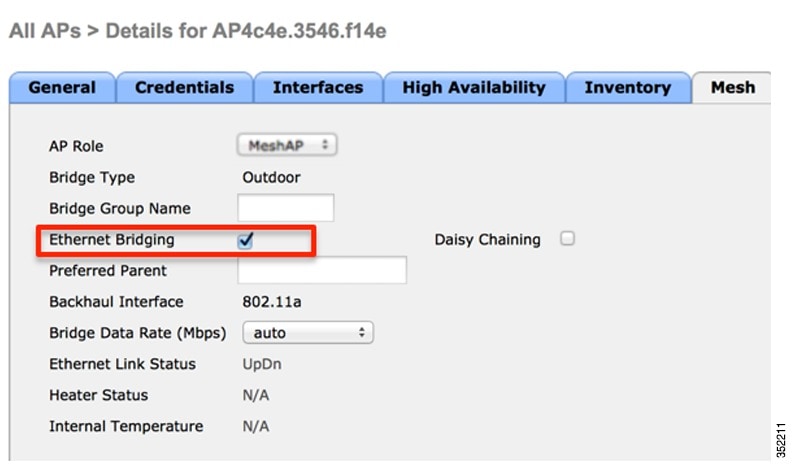
- Ethernet Bridging must be enabled on the Master AP.
- Enabling Daisy Chaining using the WLC GUI
- Enabling Daisy Chaining using the WLC CLI
- Enabling Daisy Chaining Using the AP CLI
Enabling Daisy Chaining using the WLC GUI
Enabling Daisy Chaining using the WLC CLI
Ethernet Bridging must be enabled on the Master AP, which is configured as a MAP. If the Master AP is part of a multi-hop mesh network, all mesh hops must have Ethernet Bridging enabled including the RAP.
(Cisco Controller) >config ap bridging [enable/disable] <ap_name>
Daisy chaining should only be enabled on a Slave AP that is configured as a Bridge Mode Root Access Point, for all other daisy chaining configurations, daisy chaining does not need to be enabled.
(Cisco Controller) >config ap daisy-chaining [enable/disable] <ap_name>
(Cisco Controller) >show ap config general <ap_name>
Daisy Chaining .................................. Disabled
Enabling Daisy Chaining Using the AP CLI
Daisy-chaining should only be enabled on a Slave AP that is configured as a Bridge Mode Root Access Point, for all other daisy chaining configurations, daisy chaining does not need to be enabled.
AP#capwap ap daisy-chaining <enable/disable>
The Master MAP must have Ethernet Bridging Enabled.
Preferred Parent
- Preferred parent is the best parent.
- Preferred parent has a link SNR of at least 20 db.
- Preferred parent has a link SNR in the range 12 dB to 20 dB, but no other parent is significantly better (SNR more than 20% is better). For SNR lower than 12 dB, the configuration is ignored.
- Preferred parent is not blacklisted.
- Preferred parent is not in silent mode because of dynamic frequency selection (DFS).
- Preferred parent is in the same bridge group name (BGN). If the configured preferred parent is not in the same BGN, and no other parent is available, the child will join the parent AP using the default BGN.
Note | Only Bridge Mode MAPs should be set with a preferred parent. |
Set a Preferred Parent via the WLC GUI
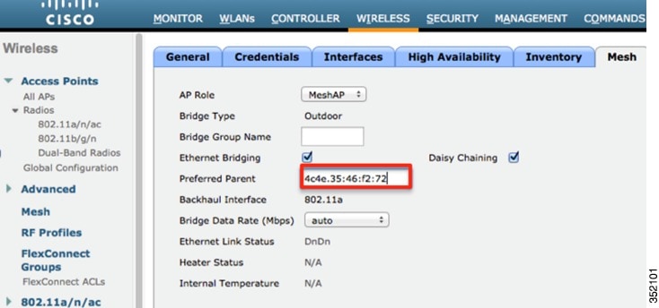
Note | When the preferred parent is entered, no other mesh configurations can be submitted at the same time. You must apply the changes, wait 90 seconds, then other mesh changes can be made. |
Note | To clear the Preferred Parent text box, the value "none" must be entered then submitted. |
Set a Preferred Parent via the WLC CLI
(Cisco Controller) >config mesh parent preferred <ap_name> <PARENT_MAC_ADDRESS>
(Cisco Controller) >show ap config general <ap_name>
Mesh preferred parent ........................... 00:24:13:0f:92:00
Bridge Group Name
Note | BGN misconfigurations will cause network instability. |
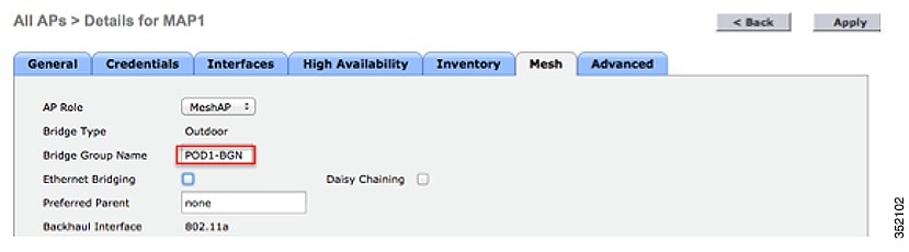
Setting a BGN using the WLC GUI
Setting a BGN Using the WLC CLI
Cisco Controller) >config ap bridgegroupname set MESH-BGN AP_NAME
Deployment Modes
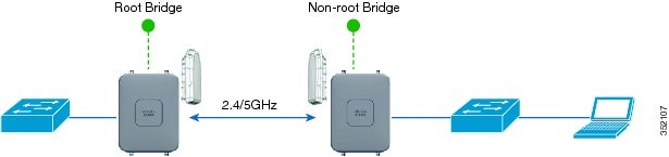
Bridge Mode Deployment
Local/Flexconnect Deployment
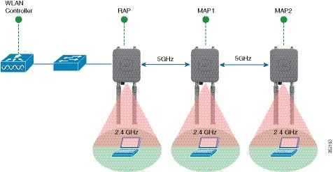
Daisy Chaining as a Serial Backhaul
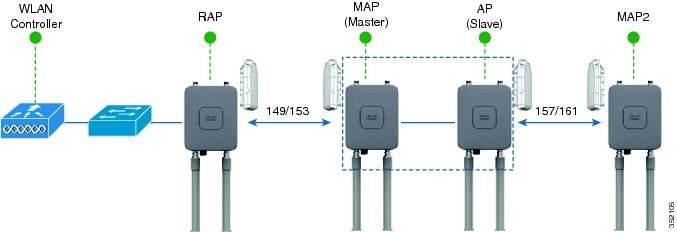
- Only 1532s in Bridge Mode can utilize this configuration.
- Master MAP & Slave MAP are operating on different 5 GHz channels to maximize throughput across the mesh link.
- BGN configuration and the Preferred Parent command are recommended to maintain the mesh tree.
- Slave MAP must be configured in RAP Mode.
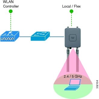
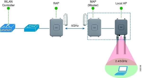
Extended Universal Access Using Daisy Chaining
Autonomous Deployment
Autonomous Software
Autonomous Operating Modes
Unified to Autonomous Conversion
AP#capwap ap autonomous
Convert to Autonomous image. Proceed? (yes/[no]):
Note | This command should only be issued once, during initial priming of the Access Point. |
AP#archive download-sw /force-reload /overwrite tftp://<tftp ip address>/<image name.tar>

AP#archieve download-sw /force-reload /overwrite tftp://10.0.0.5/ap1g3-k9w7-tar
Note that the k9w7 denotes the autonomous image. The autonomous image can be found at cisco.com.
Autonomous to Unified Conversion
AP#archive download-sw /force-reload /overwrite tftp://<tftp ip address>/<image name.tar>

AP#archieve download-sw /force-reload /overwrite tftp://10.0.0.5/ap1g3-k9w8-tar
Note that the k9w8 denotes the unified image. The unified image can be found at cisco.com.
Autonomous LED Flashing Sequence for Link Alignment
| Signal Level (dBm) | LED (Status) |
|---|---|
| >-44 | Constant green |
| –47 to –44 | Blinking green fast |
| –50 to –47 | Blinking green medium |
| –53 to –50 | Constant amber |
| –57 to –53 | Blinking amber fast |
| –60 to –57 | Blinking amber medium |
| –63 to –60 | Blinking amber slow |
| –66 to –63 | Blinking red slow |
| –69 to –66 | Blinking red medium |
| –72 to –69 | Blinking red fast |
| –75 to –72 | Constant red |
| < –75 | Off |
Range and Capacity Calculator
The Range and Capacity Calculator is available on cisco.com
Design and Planning with the 1532 Access Point
Deploying an outdoor mesh network requires careful planning and design. RF Nature: Not an Exact Science, Especially in Unlicensed Spectrum. There can be many other devices that can interfere with our mesh network. To optimize the deployment we can follow these recommendations:
- Mesh: AP-to-AP Backhaul Distance Capability should be - 2x AP-to-Client.
- WiFi Network Planning
Involves:
- Site Survey to Identify: AP Location & Height, Line-of-Sight (LoS)/Partial LoS, Interference, Access to wired backhaul (i.e. Max # Hops).
- Knowledge of the client type (Smart Phones, Tablets, Laptops).
- User Experience: Minimum Throughput to User, Type of Applications (Internet, Video, Gaming).
- CAPEX & OPEX available for project: Match to type of Service, and Robustness of Coverage.
- Regulatory Considerations: different countries allow different Tx power at different Frequency Bands.
- When to use internal antenna 1532 versus the external antenna 1532.
- Height: APs are at 33 Ft (10 m), and Client at 3.3 ft (1 m)
- Throughput: > 1 Mbps
- Decreasing AP-AP distance improves consumer experience (throughput, latency).
- Near LoS suburban. For Less LoS Scenarios; Reduce Distance Assumptions.
- Flat Terrain Environment.
- Comparing the 1532I to the 1532E with AIR-ANT2547V-N dual band antennas. The 1532E with high-gain antennas can reach much greater AP to AP distances.
Troubleshooting
| Type | LED State | AP Action |
|---|---|---|
| Boot loader status sequence | Blinking GREEN | DRAM memory test in progress |
| DRAM memory test OK | ||
| Board initialization in progress | ||
| Initializing FLASH file system | ||
| FLASH memory test OK | ||
| Initializing Ethernet | ||
| Ethernet OK | ||
| Starting Cisco IOS | ||
| Initialization successful | ||
| Association status | Chirping GREEN | Normal operating condition, joined to a controller, but no wireless client associated. |
| GREEN | Normal operating condition, at least one wireless client association. | |
| Operating status | Blinking AMBER | Software upgrade in progress. |
| Cycling through GREEN, RED, and AMBER | Discovery/join process in progress. | |
| Rapidly cycling through RED, GREEN, AMBER, and OFF | Access Point location command invoked | |
| Blinking RED | Ethernet link not operational | |
| Boot loader warnings | Blinking AMBER | Configuration recovery in progress (MODE button pushed for 2 to 3 seconds) |
| RED | Ethernet failure or image recovery (MODE button pushed for 20 to 30 seconds) | |
| Blinking GREEN | Image recovery in progress (MODE button released) | |
| Boot loader errors | RED | DRAM memory test failure. |
| Blinking RED and AMBER | FLASH file system failure. | |
| Blinking RED and off | Environment variable failure. | |
| Bad MAC address. | ||
| Ethernet failure during image recovery. | ||
| Boot environment failure. | ||
| No Cisco image file. | ||
| Boot failure. | ||
| Cisco IOS errors | RED | Software failure; try disconnecting and reconnecting unit power. |
| Cycling through RED, GREEN, AMBER, and OFF | General warning; insufficient inline power. |
 Feedback