Deployment Workflow
The following figure illustrates the deployment workflow of VNF on CVIM in Ultra M C2.1 micropod model.

The documentation set for this product strives to use bias-free language. For the purposes of this documentation set, bias-free is defined as language that does not imply discrimination based on age, disability, gender, racial identity, ethnic identity, sexual orientation, socioeconomic status, and intersectionality. Exceptions may be present in the documentation due to language that is hardcoded in the user interfaces of the product software, language used based on RFP documentation, or language that is used by a referenced third-party product. Learn more about how Cisco is using Inclusive Language.
Ultra M is a multi-product solution. Detailed instructions for installing each of these products is beyond the scope of this document. Instead, the sections that follow identify the specific, non-default parameters that must be configured through the installation and deployment of those products in order to deploy the entire solution.
The following figure illustrates the deployment workflow of VNF on CVIM in Ultra M C2.1 micropod model.
Before deploying the Ultra M solution, it is very important to develop and plan your deployment.
Networking Overview provides a general overview and identifies basic requirements for networking the Ultra M solution.
See the Network Definitions (Layer 2 and 3) Appendix to help plan the details of your network configuration.
This section describes the procedure to install all the components included in the Ultra M Solution.
To ensure hardware components of the Ultra M solution are installed properly, refer to the installation guides for the respective hardware components.
UCS C220 M5SX Server — https://www.cisco.com/c/en/us/td/docs/unified_computing/ucs/c/hw/C220M5/install/C220M5.html
Table 1 provides details for the recommended rack layout for the Ultra M C2.1 micropod deployment model.
|
Rack Layout for C2.1 - Rack W8 |
||
|---|---|---|
|
RU Numbering |
Rack |
|
|
39 |
SW4 |
Nexus 9364C |
|
38 |
||
|
37 |
SW3 |
Nexus 9364C |
|
36 |
||
|
35 |
SW2 |
Nexus 93108TC-FX |
|
34 |
SW1 |
Nexus 93108TC-FX |
|
21 to 33 |
Empty |
Empty |
|
20 |
Compute16 |
UCSC-C220-M5SX |
|
19 |
Compute15 |
UCSC-C220-M5SX |
|
18 |
Compute14 |
UCSC-C220-M5SX |
|
17 |
Compute13 |
UCSC-C220-M5SX |
|
16 |
Compute12 |
UCSC-C220-M5SX |
|
15 |
Compute11 |
UCSC-C220-M5SX |
|
14 |
Compute10 |
UCSC-C220-M5SX |
|
13 |
Compute9 |
UCSC-C220-M5SX |
|
12 |
Compute8 |
UCSC-C220-M5SX |
|
11 |
Compute7 |
UCSC-C220-M5SX |
|
10 |
Compute6 |
UCSC-C220-M5SX |
|
9 |
Compute5 |
UCSC-C220-M5SX |
|
8 |
Compute4 |
UCSC-C220-M5SX |
|
7 |
Compute3 |
UCSC-C220-M5SX |
|
6 |
Compute2 |
UCSC-C220-M5SX |
|
5 |
Compute1 |
UCSC-C220-M5SX |
|
4 |
Micropod3 |
UCSC-C220-M5SX |
|
3 |
Micropod2 |
UCSC-C220-M5SX |
|
2 |
Micropod1 |
UCSC-C220-M5SX |
|
1 |
CVIM Manager |
UCSC-C220-M5SX |
After the hardware has been installed, install all power and network cabling for the hardware using the information and instructions in the documentation for the specific hardware product. Refer to Related Documentation, on page 42 for links to the hardware product documentation. Ensure that you install your network cables according to your network plan.
All of the switches must be configured according to your planned network specifications.
 Important |
Refer to Network Planning for information and consideration for planning your network. |
Refer to the user documentation for each of the switches for configuration information and instructions:
UCS-C hardware preparation is performed through the Cisco Integrated Management Controller (CIMC).
Refer to the UCS C-series product documentation for more information:
UCS C-Series Hardware — https://www.cisco.com/c/en/us/support/servers-unified-computing/ucs-c220-m5-rack-server/model.html
Important |
Part of the UCS server preparation is the configuration of virtual drives. If there are virtual drives present which need to be deleted, select the Virtual Drive Info tab, select the virtual drive you wish to delete, then click Delete Virtual Drive. Refer to the CIMC documentation for more information. |
Important |
The information in this section assumes that the server hardware was properly installed per the information and instructions in Cable the Hardware. |
For servers based on UCS M5SX boxes set the following for BIOS parameters:
All Onboard LOM Ports—Enabled
LOM Port 1 OptionROM—Disabled
LOM Port 2 OptionROM—Disabled
PCIe Slot:1 OptionROM—Enabled
PCIe Slot:2 OptionROM—Enabled
MLOM OptionROM—Enabled
MRAID OptionROM—Enabled
For other parameters, leave it at their default settings.
Additional steps should be performed to setup C-series pod with Intel NIC. In the Intel NIC testbed, each C-series server has 2, 4-port Intel 710 NIC cards. Ports A, B, and C for each Intel NIC card has to be connected to the respective TOR. Also, ensure that the PCI slot in which the Intel NIC cards are inserted are enabled in the BIOS setting (BIOS > Configure BIOS >Advanced > LOM and PCI Slot Configuration -> All PCIe Slots OptionROM-Enabled and enable respective slots). To identify the slots, check the slot-id information under the Network-Adapter tab listed under the Inventory link on the CIMC pane. All the Intel NIC ports should be displayed in the BIOS summary page under the Actual Boot Order pane, as IBA 40G Slot xyza with Device Type is set to PXE.
Table 1 lists the non-default parameters that must be configured per server type.
|
Parameters and Settings |
Description |
|---|---|
|
Processor Configuration |
|
|
Enhanced Intel Speedstep |
Whether the processor uses Enhanced Intel SpeedStep Technology, which allows the system to dynamically adjust processor voltage and core frequency. This technology can result in decreased average power consumption and decreased average heat production. This can be one of the following:
Default value: disabled We recommend that you contact your operating system vendor to make sure the operating system supports this feature. |
|
Turbo Boost |
Whether the processor uses Intel Turbo Boost Technology, which allows the processor to automatically increase its frequency if it is running below power, temperature, or voltage specifications. This can be one of the following:
Default value: disabled |
|
Hyper Threading |
Whether the processor uses Intel Hyper-Threading Technology, which allows multithreaded software applications to execute threads in parallel within each processor. This can be one of the following:
Default value: enabled We recommend that you contact your operating system vendor to make sure the operating system supports this feature. |
|
Core Multi Processing |
Sets the state of logical processor cores in a package. If you disable this setting, Hyper Threading is also disabled. This can be one of the following: all—Enables multi processing on all logical processor cores. 1 through 10—Specifies the number of logical processor cores that can run on the server. To disable multi processing and have only one logical processor core running on the server, select 1. Platform Default—The BIOS uses the value for this attribute contained in the BIOS defaults for the server type and vendor. Default value: all We recommend that you contact your operating system vendor to make sure the operating system supports this feature. |
|
Power/Performance |
|
|
CPU Performance |
Sets the CPU performance profile for the server. This can be one of the following:
Default value: high-throughput |
|
Workload Configuration |
Set the value of this parameter as IO sensitive. |
|
Fan Policy |
Set the Fan Policy for the server to High Power as mentioned in the https://www.cisco.com/en/US/docs/unified_computing/ucs/c/sw/gui/config/guide/1.5/b_Cisco_UCS_C-series_GUI_Configuration_Guide.151_chapter_011.html#concept_8CB787DF70304E98BE25D120466418B9. This setting can be used for server configurations that require fan speeds ranging from 60% to 85%. This policy is ideal for servers that contain PCIe cards that overheat easily and have high temperatures. The minimum fan speed set with this policy varies for each server, but it is approximately in the range of 50 to 85%. |
|
Memory |
|
|
NUMA |
Whether the BIOS supports NUMA. This can be one of the following:
Default value: enabled |
Within the Ultra M solution, Cisco Virtualized Infrastructure Manager (CVIM) functions as the virtual infrastructure manager (VIM).
The method by which the VIM is deployed depends on the architecture of your Ultra M model. For the micropod model, see the https://www.cisco.com/c/en/us/td/docs/net_mgmt/network_function_virtualization_Infrastructure/2_4_3/install_guide/Cisco_VIM_Install_Guide_2_4_3/Cisco_VIM_Install_Guide_2_4_3_chapter_00.html.
This section describes the following topics:
USP-based VNFs can be deployed using a AutoVNF instance in generic mode. In this scenario, AutoVNF VM (in HA mode) is deployed on the VIM and is used to deploy VNFM and VNF(s).
Important |
AutoVNF deploys Cisco Elastic Services Controller (ESC) as the VNFM and is only supported VNFM in this release. |
A single AutoVNF can deploy one or more VNFs in one or more tenants within the same VIM.
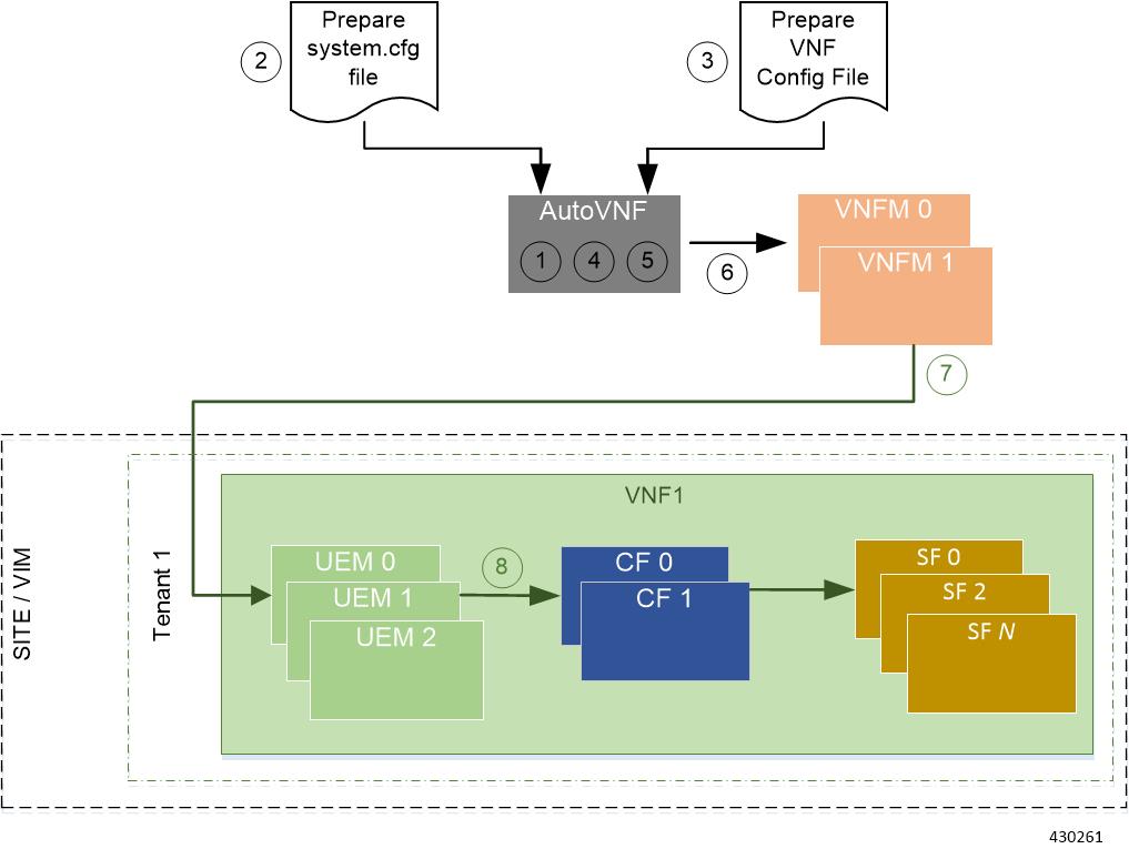
Figure 1 and Figure 2 provide an overview of the VNF deployment automation process for when using AutoVNF in generic mode. Details are provided in Table 1.
NOTES:
The workflow described in this section is supported only with VNF deployments performed through AutoVNF and that are based on OSP 10.
This information assumes that you have deployed the NFVI and VIM.
This information assumes that all artifacts required during configuration must be pre-created in OpenStack.

|
Callout |
Description |
||
|---|---|---|---|
|
1 |
Deploy AutoVNF using the boot_uas.py script provided as part of the release ISO. |
||
|
2 |
Prepare the system.cfg file to the AutoVNF VM. This file provides the VNF’s Day-0 configuration. |
||
|
3 |
Prepare the AutoVNF configuration file that is used by AutoVNF to initiate the VNFM and VNF deployment process. This file includes the configuration information required to deploy VNFM and all the VNF components (VNFCs) such as secure tokens, network catalogs, VDU catalogs, and VDUs. |
||
|
4 |
On the AutoVNF VM, load and commit the AutoVNF configuration file prepared in the previous step. Once commited, activate the loaded AutoVNF configuration file to deploy the VNFMs. |
||
|
5 |
Once VNFMs are ready, AutoVNF pushes the artifacts to bring up the VNF. |
||
|
6 |
AutoVNF passes the VNF configuration to the VNFM VM instance.
It ensures that the various VM catalogs pertaining to other VNFCs are on-boarded by the VNFM. It accomplishes this through a number of YANG-based definitions which are then used to configure various aspects of the virtualized environment using REST and NETCONF APIs. That VNFM mounts the VNFC catalogs and works with AutoVNF to deploy the various components that comprise the desired VNF use-case (e.g. UGP). |
||
|
7, 9 |
The VNFM leverages the VNFC information to deploy the UEM VMs cluster. Though the USP architecture represents a single VNF to other network elements, it is comprised of multiple VM types each having their own separate catalogs. The UEM component of the USP works with the VNFM to deploy these catalogs based on the intended VNF use case (e.g. UGP, etc.). |
||
|
8, 10 |
The UEM processes the Day-0 configuration information it received from the VNFM and deploys the Control Function (CF) and Service Function (SF) VNFC VMs. Once all the VNF components (VNFCs) have been successfully deployed, AutoVNF notifies AutoDeploy.
|
Prior to installing the USP, please ensure that the following is true:
The prerequisite hardware is installed and operational with network connectivity.
The prerequisite software is installed and configured and functioning properly:
You have administrative rights to the operating system.
VIM Orchestrator is properly installed and operational.
VIM components are properly installed and operational. This configuration includes networks, flavors, and sufficient quota allocations to the tenant.
Note |
Supported and/or required flavors and quota allocations are based on deployment models. Contact your Cisco representative for more information. |
You have administrative rights to the OpenStack setup.
The Cisco USP software ISO has been downloaded and is accessible by you.
The AutoVNF software roles within the Ultra Automation Services (UAS) is used to automate the USP-based VNF deployment. The automated deployment process through AutoVNF is described in VNF Deployment Automation Overview.
To deploy the USP-based VNF using AutoDeploy:
The files required to deploy the USP components are distributed as RPMs (called “bundles”) in a single ISO package. They are maintained using YUM on the Onboarding Server. The following bundles are part of the ISO:
|
USP Bundle Name |
Description |
|---|---|
|
usp-em-bundle |
The Element Manager (EM) Bundle RPM containing images and metadata for the Ultra Element Manager (UEM) module. |
|
usp-uas-bundle |
The Ultra Automation Services Bundle RPM containing AutoIT, AutoDeploy, AutoVNF, Ultra Web Services (UWS), and other automation packages. |
|
usp-ugp-bundle |
The Ultra Gateway Platform (UGP) Bundle RPM containing images for Ultra Packet core (VPC-DI). This bundle contains non-trusted images. |
|
usp-vnfm-bundle |
The VNFM Bundle RPM containing an image and a boot-up script for ESC (Elastic Service Controller). |
|
usp-yang-bundle |
The Yang Bundle RPM containing YANG data models including the VNFD and VNFR. |
|
usp-auto-it-bundle |
The bundle containing the AutoIT packages required to deploy the UAS. |
|
ultram-manager |
This package contains the script and relevant files needed to deploy the Ultra Health Service. |
In addition to the bundles, the ISO bundle also includes scripts used to deploy the bundles including UAS.
Before proceeding with these instructions, ensure that the prerequisites identified in USP Installation Prerequisites chapter of the Cisco Ultra Services Platform Deployment Automation Guide have been met.
To onboard the ISO package:
Log on to the Onboarding Server.
Download the USP ISO bundle and related files pertaining to the release.
Create a mount point on the Onboarding Server and mount the ISO package:
mkdir /var/usp-iso Mount the USP ISO.
sudo mount -t iso9660 -o loop <ISO_download_directory>/<ISO_package_name> /var/usp-iso Example: The following command mounts the ISO bundle called usp-5_5_0-1255.iso located in a directory called 5_5_0-1283 to /var/usp-iso:
sudo mount -t iso9660 -o loop 5_5_0-1064/usp-5_5_0-1064.iso /var/usp-iso mount: /dev/loop1 is write-protected, mounting read-onlyVerify the mount configuration.
df –h Example output:
Filesystem      Size  Used Avail Use% Mounted on
/dev/sda2       187G  178G  316M 100% /
devtmpfs         63G     0   63G   0% /dev
tmpfs            63G  4.0K   63G   1% /dev/shm
tmpfs            63G  1.4M   63G   1% /run
tmpfs            63G     0   63G   0% /sys/fs/cgroup
/dev/sda1       477M  112M  336M  25% /boot
tmpfs            13G     0   13G   0% /run/user/0
/dev/loop1      4.2G  4.2G     0 100% /var/usp-iso
Proceed to Extract the UAS Bundle.
Once the USP ISO has been mounted, the UAS bundle must be extracted from the ISO in order to prepare the configuration files required for deployment.
These instructions assume you are already logged on to the Onboarding Server.
To extract the UAS bundle:
Navigate to the tools directory within the ISO mount.
cd /var/usp-iso/tools/ Launch the usp-uas-installer.sh script.
sudo ./usp-uas-installer.sh The script extracts the files that comprise the UAS bundle to /opt/cisco/usp/uas-installer.
Verify that files have been extracted.
Example output:
ll /opt/cisco/usp/uas-installer total 12
drwxr-xr-x. 5 root root 4096 May 11 08:04 common
drwxr-xr-x. 2 root root 4096 May 11 08:04 images
drwxr-xr-x. 2 root root 4096 May 11 08:04 scripts
ll /opt/cisco/usp/uas-installer/images/ total 707580
-rw-r--r--. 1 root root 723898880 May 10 15:40 usp-uas-1.0.0-601.qcow2
ll /opt/cisco/usp/uas-installer/scripts/ total 56
-rwxr-xr-x. 1 root root 5460 May 11 08:04 autoit-user.py
-rwxr-xr-x. 1 root root 4762 May 11 08:04 encrypt_account.sh
-rwxr-xr-x. 1 root root 3945 May 11 08:04 encrypt_credentials.sh
-rwxr-xr-x. 1 root root 13846 May 11 08:04 uas-boot.py
-rwxr-xr-x. 1 root root 5383 May 11 08:04 uas-check.py
-rwxr-xr-x. 1 root root 10385 May 11 08:04 usp-tenant.py
Proceed to Deploy the AutoVNF VM.
The VM for AutoVNF is deployed using boot_uas.py script provided with the UAS bundle. The script is located in the following directory:
/opt/cisco/usp/bundles/uas-bundle/tools
This script includes a number of deployment parameters for the VM. These parameters are described in the help information pertaining to the script which can be accessed by executing the following command:
./boot_uas.py –h For the help information, see the boot_uas.py Help Appendix in the Cisco Ultra Services Platform Deployment Automation Guide.
Important |
These instructions assume you are already logged on to the Onboarding Server. |
To deploy the AutoVNF VM:
Navigate to the directory containing the boot_uas.py file.
cd /opt/cisco/usp/bundles/uas-bundle/tools Deploy the AutoVNF VM.
./boot_uas.py --autovnf --openstack --image <image_name> --flavor <flavor_name> --net <network_name> There are additional arguments that can be executed with this script based on your deployment scenario. For details, see the boot_uas.py Help Appendix in the Cisco Ultra Services Platform Deployment Automation Guide.
Important |
Both version 2 and 3 of OpenStack Keystone APIs are supported. You can specify the desired version using the --os_identity_api_version argument with this script. For example to specify the use of version 3, add the argument --os_identity_api_version 3. The default is version 2. |
Upon executing the script, you are prompted to enter user crendentials for performing operations within the AutoVNF VM.
Provide the requested information.
AutoVNF VM Login Password: The password for the default user account, which is named ubuntu.
AutoVNF API Access password for "admin": The password for the ConfD administrator user, which is named admin.
AutoVNF API Access password for "oper": The password for the ConfD operator user, which is named oper.
AutoVNF API Access password for "security": The password for the ConfD security administrator user, which is named security-admin.
Important |
Ensure that all passwords meet the requirements specified in Password Requirements and Login Security section in the Cisco Ultra Services Platform Deployment Automation Guide. |
Log on to the AutoVNF VM as ubuntu. Use the password that was created earlier for this user.
Become the root user.
sudo -i Prepare the system.cfg file. This will serve as the Day-0 config for the VNF. Refer to Sample system.cfg File for an example configuration file.
Important |
Though administrative user credentials can be specified in clear text in the system.cfg file, it is not recommended. For security purposes, it is recommended that you configure a secure token for the user account in the VNF configuration file and reference that file as part of the VDU catalog pertaining to the CF using the login-credential parameter. In the system.cfg file, use the $CF_LOGIN_USER and $CF_LOGIN_PASSWORD variables as follows to call the values configured for the secure token: |
Prepare the AutoVNF configuration file.
This file provides the VNF configuration information used by AutoVNF during the deployment process. A sample configuration file is provided for reference in Sample AutoVNF Configuration File.
Save the AutoVNF configuration file to your home directory on the AutoVNF VM.
Upload the USP ISO to home directory on AutoVNF.
Proceed to Activate the AutoVNF Configuration Files.
Once you have completed preparing your AutoVNF configuration files, you must load the configuration and activate the deployment.
Important |
User credentials are configured through Secure Tokens specified in the configuration file. Ensure that passwords configured with Secure Token meet the requirements specified in the Password Requirements and Login Security section of Cisco Ultra Services Platform Deployment Automation Guide. |
Once activated, AutoVNF proceeds with the deployment automation workflow as described in VNF Deployment Automation Overview.
Important |
These instructions assume you are already logged on to the AutoVNF VM as the root user and that your configuration files have been prepared for your deployment as per the information and instructions in Deploy the AutoVNF VM. These instructions also assume that AutoVNF has access to the VNFC image files (either locally or on a remote server) provided with the USP ISO. |
To activate the USP deployment using AutoVNF:
Login to the ConfD CLI as the admin user.
confd_cli –u admin –C Enter the ConfD configuration mode.
config Load the AutoVNF configuration file to load the VNFM and VNF information into the AutoVNF database.
load merge  <your_autovnf_file_name> .cfg
commit
end
Important |
If you are performing this process as a result of an upgrade or redeployment, you must use the load replace variant of this command: |
Activate the AutoVNF configuration file.
activate nsd <nsd_name> Important |
The output of this command is a transaction-id which can be used to monitor the deployment progress. If need be, the VIM deployment can be deactivated using the deactivate variant of this command. |
Once VNFM is deployed and ready, activate the VNF NSD configuration file.
activate nsd <nsd_name> vnfd <vnf> Important |
The output of this command is a transaction-id which can be used to monitor the deployment progress. If need be, the VIM deployment can be deactivated using the deactivate variant of this command. |
Monitor the progress of the deployment by viewing transaction logs:
show log <transaction_id> | display xml transaction_id is the ID displayed as a result of the activate-deployment command.
The logs display status messages for each node in each VNF that the configuration file defines. Example success messages for the different components deployed through AutoVNF are shown below:
VNF:
Fri May 12 21:44:35 UTC 2017 [Task: 1494624612779/tb1vnfd2] Successfully completed all Vnf DeploymentsEntire Deployment:
Fri May 12 21:57:38 UTC 2017 [Task: 1494624612779] SuccessImportant |
If there are any issues seen when executing the above commands, see the Monitoring and Troubleshooting the Deployment section in the Cisco Ultra Services Platform Deployment Automation Guide. |
Use the following procedure to upgrade or redeploy the AutoVNF software image in scenarios where AutoVNF was brought up as stand-alone instance.
Important |
These instructions assume you are already logged on to the Onboarding Server. |
Delete the AutoVNF VM instance.
./boot_uas.py --openstack --autovnf --delete <transaction_id> Optional. If required remove the OpenStack artifacts which were created manually to bring up AutoVNF.
Follow the procedures in Deploy the USP-based VNF to redeploy AutoVNF with the new software version.
Note |
Upgrading or redeploying the VNF can be performed as part of this process or it can be performed separately. For details and instructions, see the Upgrading/Redeploying VNFs Deployed Through a Stand-alone AutoVNF Instance section in the Cisco Ultra Services Platform Deployment Automation Guide. |
 Feedback