Tested Deployment and Site Models for UC 10.0(1)
Available Languages
Table Of Contents
Tested Deployments and Site Models
Multisite Distributed Deployment Options
Multisite Centralized Call Processing with SRST Router
Multisite with Distributed Call Processing
Unified Communications on Virtualized Servers
Cisco Unified Communications Manager — Session Management Edition Site
Large Multisite Centralized with Unified SRST
Medium Site Centralized with Unified SRST
Cisco Unified Communications Manager Session Management Edition
Tested Deployments and Site Models
Cisco Collaboration Systems Release 10.0(1) testing for IP telephony is designed to test the hardware and software components that work together in a multisite distributed IP telephony deployment.
For this testing, the following site models were created. Each site model was designed to test a specific set of features and interactions. The site models can be used in various combinations to create different versions of a multisite distributed deployment model.
•
Site models:
–
–
–
–
–
–
–
–
–
–
–
–
This topic describes each site model.
For additional guidelines, recommendations, and best practices for implementing enterprise networking solutions, refer to the Cisco Solution Reference Network Design (SRND) guides and related documents, which are available at this URL:
For a list of the release versions of the components used in the site models, see System Release Notes for IP Telephony: Cisco Collaboration Systems, Release 10.0(1)
This topic includes the following sections:
•
Purpose of Solution Tests
An efficient, effective, and reliable IP telephony solution requires many interrelated hardware and software components. The site models that are described in this manual provide you with models and guidance as you implement an IP telephony system for your organization. Cisco has selected, installed, configured, and tested hardware and software designed to work together seamlessly and to provide a complete and optimized IP telephony solution.
Each site model addresses some or all of the following issues:
•
•
•
•
•
•
•
•
•
•
•
•
•
•
•
Multisite Distributed Deployment Options
The site models within each test group (North America and EUEM) can be implemented in various combinations to create deployment models to meet the needs of a wide range of organizations.
For detailed information about the sites used in IP telephony deployments, see the Site Models.
The Solution integration test bed topologies diagrams for NA and EUEM for IP telephony tested in Cisco Unified CommunicationsRelease 10.0(1) is available from the Resource Library tab of the Technical Information Site.
Site Models
Different site models were created and tested for Cisco Unified Communications Release 10.0(1) testing for IP telephony. Each site model tested specific hardware and software components, features, functions, protocols, and related items.
A site model includes one or more sites. Each site has a three-letter name (for example, SFO, ORD, and SJC). Examples throughout this manual refer to these site names.
The following sections describe each site model in detail. Each section includes an explanation of the design characteristics of the site model, and includes a table that lists the hardware and software components used in the model. The tables contain the following information for each component:
•
•
•
Table 1 lists the site models and references to sections that provide detailed information.
Table 1 Site Models
San Francisco (SFO), Chicago (ORD)
San Jose (SJC), Rockford (RFD), and Dallas (DFW)
ICT traffic between all sites, including the CME sites Toronto (YYZ), and Atlanta (ATL)
San Jose (SJC), Rockford (RFD), San Francisco (SFO), Chicago (ORD), and Kansas City (MCI), Los Angeles (LAX)
San Jose (SJC), Rockford (RFD), Dallas (DFW), Kansas City (MCI), Los Angeles (LAX), and San Francisco (SFO), Chicago (ORD)
Kansas City (MCI), Los Angeles (LAX) talking to San Jose (SJC), Rockford (RFD), San Francisco (SFO), Chicago (ORD), Dallas (DFW), Toronto (YYZ) and Atlanta (ATL)
Cisco Unified Communications Manager — Session Management Edition Site
Kansas City (MCI), Los Angeles (LAX)
Paris (CDG)
Geneva (GVA)
Cisco Unified Communications Manager Session Management Edition
Co-located in Paris (CDG-SME) and Geneva (GVA-SME)
Warsaw (WAW)
Multisite Centralized Call Processing with SRST Router
The Multisite Centralized Call Processing with Remote Site Survivability (SRST Router) site model represents a very large financial company deployment in which two sites, San Francisco (SFO) and Chicago (ORD), are used to cluster Cisco Unified Communications Manager over an IP WAN. In this model, half of the cluster resides in SFO and the other half in ORD. These sites provide centralized call processing to remote Cisco Unified Survivable Remote Site Telephony (Unified SRST) sites. Communication with remote sites takes place over the IP WAN.
Remote sites are connected to the WAN. Each site supports approximately equal volumes of network traffic, and each is capable of carrying 100 percent of the traffic in the event of a failure in the other's network. Cisco 2900 series Integrated Services Routers are configured with Hot Standby Routing Protocol (HSRP) and Survivable Remote Site Telephony (SRST). For load sharing between the sites, Multi-group HSRP (MHSRP) is configured.
The Cisco Integrated Services Routers provide gateway connectivity to Public Switched Telephone Network (PSTN) providers using T1/E1 primary rate interfaces (2 PRIs). Each remote site is connected to a Cisco Catalyst 37xx series Switch, which connects VoIP endpoints to remote sites, and also includes Power over Ethernet features to power Cisco IP Phones. Packet marking is also done at Cisco Catalyst 37xx Series switch using Modular QoS CLI (MQC) based configuration using class-map and policy-map.
The tested Multisite Centralized site model has the following design characteristics:
•
•
•
•
•
•
•
•
•
•
•
•
•
•
•
•
•
•
•
Figure 1 provides an overview of the Multisite Centralized Call Processing with SRST site model.
Figure 1 Multisite Centralized, Call Processing with SRST Model
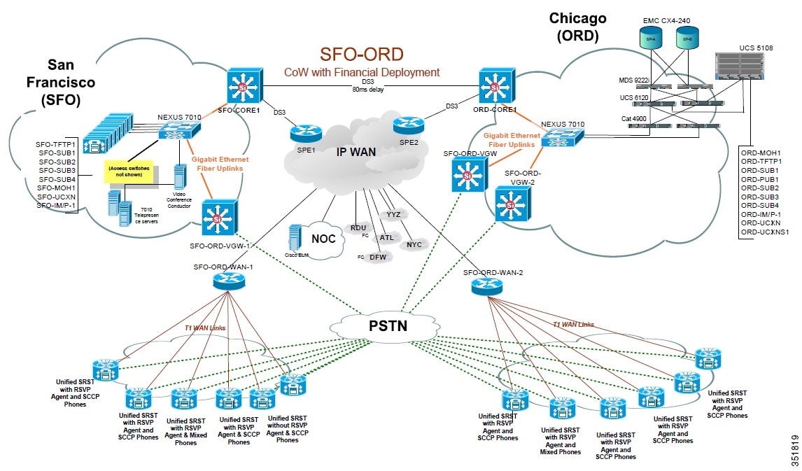
Table 2 lists the hardware and software components used in the Multisite Centralized, Clustering over the WAN with Unified SRST site model.
Campus
The Campus site model represents a very large campus in which two sites, San Jose (SJC) and Rockford (RFD), are used to cluster Cisco Unified Communications Manager over an IP WAN. This site also supports RSVP cluster.
The Cisco Unified Communications Manager cluster in this site model consists of the following:
•
•
•
•
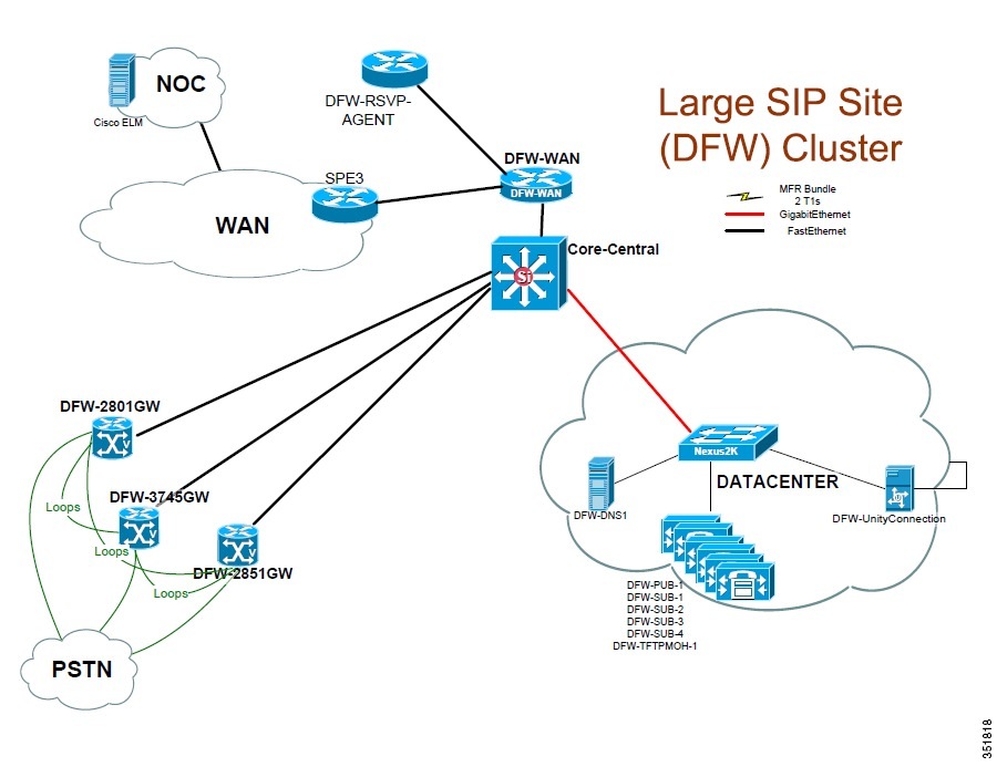
The campus site model also consists of another site called Dallas (DFW). This site includes a Cisco Unified Communications Manager cluster that includes the following:
•
•
•
This deployment model has the following characteristics:
•
•
•
•
•
•
•
•
•
•
Figure 2 shows the topology of the Campus site model.
Figure 2 Campus
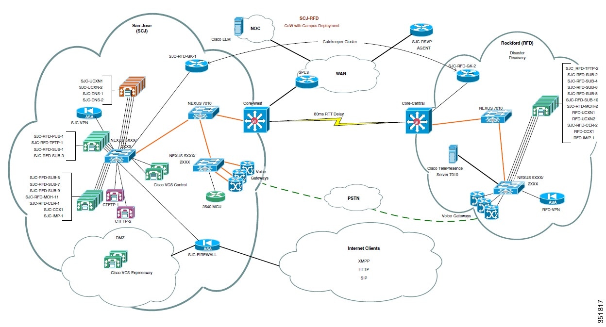
Table 3 lists the hardware and software components used in the Campus site model.
Figure 3 shows the topology of the Dallas (DFW) Site model.
Figure 3 DFW Site Model
Multisite with Distributed Call Processing
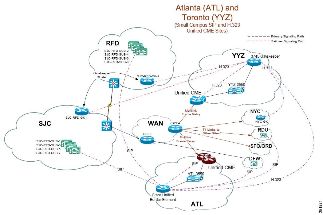
The model for a multisite deployment with distributed call processing consists of multiple independent sites, each with its own call processing agent cluster connected to an IP WAN that carries voice traffic between the distributed sites. One of these sites is called Atlanta (ATL). This site includes:
•
•
Another site is called Toronto (YYZ). This site includes:
•
•
•
The remainder of this model consists of Intercluster Trunk (ICT) traffic between the SFO/ORD, SJC/RFD, and DFW clusters. H.323 gatekeeper controlled trunks and SIP trunks are used. Location-based and End-to-End RSVP call admission control are also included in testing.
Figure 4 shows the topology of the Campus site model.
Figure 4 Multisite with Distributed Call Processing Model
Clustering Over the IP WAN
The Clustering over the IP WAN site model is used in the implementation of the SJC/RFD, SFO/ORD, and MCI-LAX clusters. It is possible to deploy a single Unified Communications Manager cluster across multiple sites that are connected by an IP WAN with QoS features enabled. Clustering over the WAN can support two types of deployments:
•
•
A combination of the two deployment models can be used to satisfy specific site requirements. For example, two main sites may each have primary and backup subscribers, with another two sites containing only a primary server each and utilizing either shared backups or dedicated backups at the two main sites.
Unified Communications on Virtualized Servers
The clusters for SFO/ORD, SJC/RFD, MCI/LAX, and DFW run on virtual machines hosted on Cisco Unified Communications Blade Servers (UCS B-Series) and Cisco UCS C-Series Rack-Mount Servers. SAN based storage is used for the B-series servers and both SAN and direct attached (disk) storage are used with the C-series servers.
•
•
This site supports a mix of 1000 SIP and SCCP endpoints.
Call Routing and Dial Plan Distribution Using Call Control Discovery for the Service Advertisement Framework
The Call Routing and Dial Plan Distribution Using Call Control Discovery for the Service Advertisement Framework site model consists of sites Kansas City (MCI), Los Angeles (LAX) talking to San Jose (SJC)/Rockford (RFD), San Francisco (SFO)/Chicago (ORD), Dallas (DFW), Toronto (YYZ) and Atlanta (ATL).
When multiple call processing agents are present in the same system, each can be configured manually to be aware of the others. This configuration can be time consuming and error prone. Call routing between the various call processing agents requires the configuration of static routes on the call agents and updating them when changes occur.
Instead, the Cisco Service Advertisement Framework (SAF) can be used to share call routing and dial plan information automatically between call agents. SAF allows non-Cisco call agents (such as TDM PBXs) to partake in the Framework when they are interconnected through a Cisco IOS gateway.
Table 4 lists the hardware and software components used in the Cisco Service Advertisement Framework (SAF) Site.
Cisco Unified Communications Manager — Session Management Edition Site
The Cisco Unified Communications Manager - Session Management Edition site model contains two sites, Kansas City (MCI) and Los Angeles (LAX), designed to simulate Session Management Edition of the Cisco Unified Communications 8.5 system train.
This cluster includes:
•
•
This deployment model has the following characteristics:
•
•
•
•
•
•
•
•
Figure 5 shows the topology of this site.
Figure 5 Cisco Unified Communications Manager — Session Management Edition (SME) Site Topology
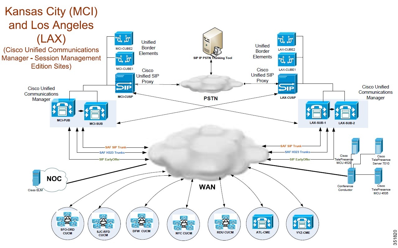
Table 5 lists the hardware and software components used in this model.
Video Enhancements
During this Release, additional video testing is included in all of the site models. Testing included adding new Tandberg video endpoints and the Cisco TelePresence System 1000. Calls between the various video endpoints, including intra-cluster calls and intercluster calls, were tested along with supplementary services such as conference, transfer, and hold.
Large Multisite Centralized with Unified SRST
The Large Multisite Centralized with Unified SRST site model consists of one site called Paris (CDG). This site model represents an international deployment with up to 8 remote sites deployed across various countries. It includes Cisco Unity Connection and third-party components. Cisco Unified Communications Manager uses QSIG, H.323, and SIP to interoperate between sites. Remote sites are interconnected through the WAN and all are RSVP-enabled to the central site. For Geneva (GVA) and Paris (CDG), inter cluster RSVP is enabled.
In this model, a Cisco Unified Communications Manager cluster serves 60 phones in local and remote locations, with all endpoints and gateways fully encrypted (RTP and signaling). PBXs that support the QSIG ISO and QSIG ECMA variants connect to this cluster through direct QSIG links. The Cluster connects to the rest of the network through MPLS WAN networks.
Calls between the CDG site, the LGW site, and the MAD site are provided by H.323 intercluster trunks. Cisco Unity Connection provides voice messaging. PBX users access voice messaging features through the QSIG trunks to Cisco Unified Communications Manager.
Access to the PSTN for normal off-net calls is provided by ten E1 ETSI PRI links to the PSTN. Remote sites have either centralized breakout to the PSTN or local PSTN breakout using E1 PRI, BRI, or FXO connections. PSTN access is controlled by Cisco Unified Communications Manager using MGCP, H.323, or SIP. Unified SRST is used in each remote site.
Access to the SIP network is provided through a SIP trunk to a remote Cisco Unified SIP Proxy (CUSP). Access to third-party services such as operator console, if available, is provided locally. Some of the sites will also have video endpoints and Cisco Unified Videoconferencing Gateways, and remote QSIG PBXs.
The Large Multisite Centralized with Unified SRST site model have these design characteristics:
•
•
•
•
•
•
•
•
•
•
•
•
•
•
•
•
•
•
•
Figure 6 shows the topology of the Large Multisite Centralized with Unified SRST Site model.
Figure 6 Large Multisite Centralized with Unified SRST Site Topology
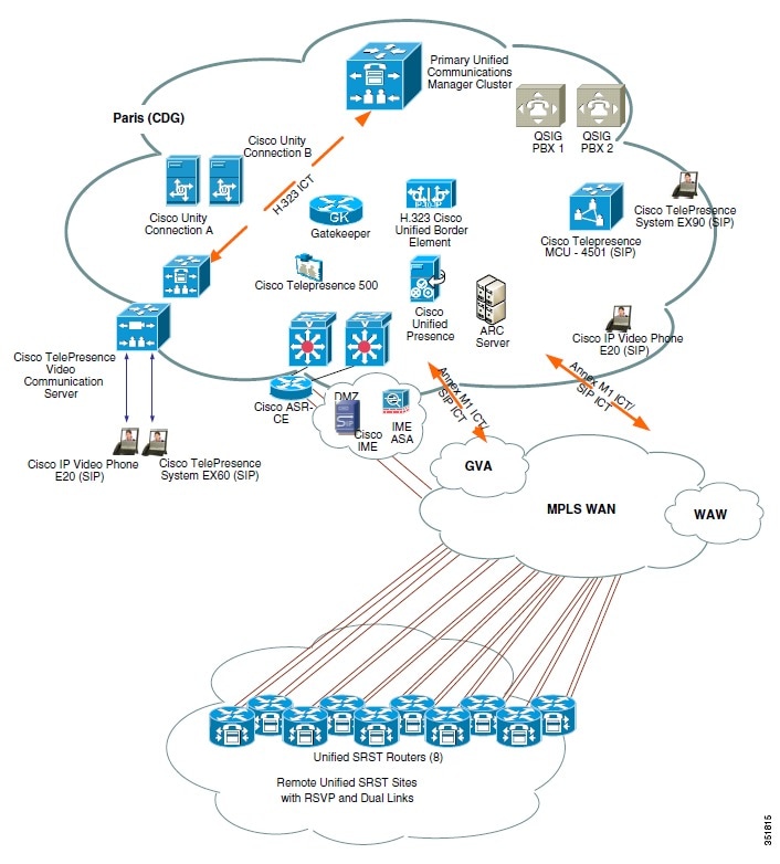
Table 6 lists the hardware and software components used in the Multisite Centralized, Clustering over the WAN with Unified SRST site model.
Table 6 Large Multisite Centralized with Unified SRST Site Model Components
Datacenter Catalyst switch
WS-C6509-E
3
Analog gateway
Cisco ATA 187 Analog Telephone Adaptor
3
Cisco Unified Communications Manager Server
Cisco UCS B Series 7, Cisco Wallop C210M2-2, Cisco UCS C 240 Series - 4
131
Firewall-ASA
Data center - 5510
1
Cisco IME - 5520
1
Cisco Unified SRST Routers
Cisco 2921
3
Cisco 2901
1
Cisco 3925
4
Cisco 3945
2
Cisco Unified Contact Center Express
Cisco B-series
2
Cisco Unified IP Phone
Cisco Unified IP Phone 7971G-GE
10
Cisco Unified IP Phone 7970G
10
Cisco Unified IP Phone 7961G/7961G-GE
5
Cisco Unified IP Phone 7941G/7941G-GE
5
Cisco Unified IP Phones models 6921, 6941, and 6961
5
Cisco Unified IP Phone 8941
1
Cisco Unified IP Phone 8945
1
Cisco IP Communicator
2
Cisco Unified Communications Integration™ for Microsoft Office Communicator
6
Cisco Unified Personal Communicator
2
Cisco Unified IP Phones 8961
5
Cisco Unity Connection
Cisco B-series
2
Core Catalyst chassis
WS-C6506-E
2
RSVP Agent
Cisco 3925
1
Cisco 1861
1
E1 gateway card
Cisco 3945
1
Gateway
Cisco 2901
2
Cisco 2911
2
Cisco 2921
2
Cisco 2951
2
Cisco 3925
2
Cisco 3945
2
Cisco 3945
1
PSTN Gateway
Cisco 3945
3
Access switch
WS-C3550-24PWR-SMI
3
WS-C3750-24PS-S
3
WS-C3750-48PS-S
2
Router
Cisco 7206-VXR
1
Video conferencing
Cisco Unified Videoconferencing MCU 3545
2
Video endpoint
Cisco Unified Video Advantage
4
Cisco IP Phone 7985
5
Cisco Unified IP Phones models 9951 and 9971, Tandberg E20, Tandberg EX90, Tandberg MXP 1700, Cisco TelePresence MX300, Cisco TelePresence SX20 Quick Set, Cisco TelePresence System Quick Set C20, Cisco TelePresence Codec C40
5
Tandberg Codian MCU
Tandberg Codian 4501
1
Video MCU and Gateway
IPVC-3545-CHAS
1
1 Divided into two Unified Communications Manager clusters: one main cluster consisting of 11 servers and a second smaller cluster of two servers supporting the Cisco Unified Contact Center Express server and agent phones.
Medium Site Centralized with Unified SRST
The Medium Site model consists of one centralized site with three SRST remote sites called Geneva (GVA). In this model, a Cisco Unified Communications Manager cluster serves 20 phones. The Cisco Unified Communications Manager cluster connects to the rest of the network through MPLS WAN networks.
A local Cisco Unity Connection provides voice messaging services for local PBX and Cisco Unified Communications Manager users. Access to the PSTN for normal off-net calls is provided by five E1 RTSI PRI links to the PSTN. Access to other sites and to services such as Cisco Unified MeetingPlace Express is provided by H.323 gatekeeper controlled trunks and an IP-to-IP gateway. Access to the SIP network is through a SIP trunk to a remotely located Cisco Unified SIP Proxy (CUSP). Third-party operator consoles are provided on Cisco Unified Communications Manager to serve local phones and to provide backup to the operator console in the CDG site.
The Medium Site model has these design characteristics:
•
•
•
•
•
•
•
•
•
•
•
•
Figure 7 shows the topology of the EUEM Medium Site model (GVA).
Figure 7 EUEM Medium Site Topology
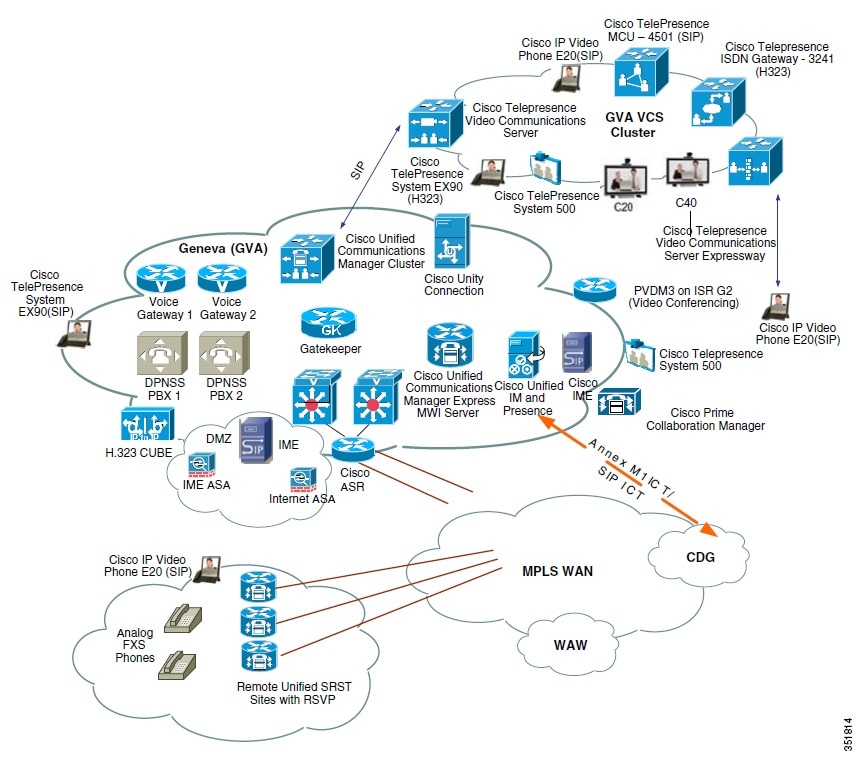
Table 7 lists the hardware and software components used in the Medium Site model.
Cisco Unified Communications Manager Session Management Edition
The Cisco Unified Communications Manager Session Management Edition deployment is a variation of multisite distributed call processing deployments model, which interconnects large numbers of Cisco Unified Communications systems. In the EUEM sites, the Cisco Unified Communications Manager Session Management Edition deployments consist of two sites: Paris (CDG-SME) and Geneva (GVA-SME).
The IPT-SI deployment for Cisco Unified Communications Manager Session Management Edition can be explained as follows:
In this deployment there are two Cisco Unified Communications Manager Session Management Edition clusters namely CDG-SME cluster and GVA-SME cluster. CDG-SME cluster is co-located with CDG site and aggregates trunks (SIP, H.323, QSIG, and QSIG over SIP) from the CDG leaf node. The GVA-SME cluster is co-located with GVA site and aggregates trunks (SIP, H.323, QSIG, and QSIG over SIP) from the GVA leaf node.
Cisco Unity Connection server provides voice mail services to Cisco Unified Communications Manager, Cisco Unified Communications Manager Session Management Edition, and remote users.
Cisco Unified Communications Manager Session Management Edition: Cisco Unified Communications Manager Session Management Edition is essentially a Cisco Unified Communications Manager cluster supporting a large number of trunk interfaces and enables the aggregation of multiple Unified Communications systems using multiple trunk types for voice, video, and fax calls.
Paris (CDG-SME) Site
The CDG-SME cluster consists of CDG leaf cluster (Cisco Unified Communications Manager Servers), Cisco Unity Connection server, Gateways, and Gatekeepers. There are two QSIG SIP trunks configured between CGD leaf and CDG-SME cluster and also between CDG-SME.
The CDG-SME cluster site model has these design characteristics:
•
•
•
•
•
•
•
Geneva (GVA-SME) site
The GVA-SME cluster consists of GVA leaf cluster (Unified Communications Manager Servers), Cisco Unity Connection server, Gateways, and Gatekeepers.
The GVA-SME cluster Site model has these design characteristics:
•
•
•
•
•
•
Table 8 lists the hardware and software components used in the Cisco Unified Communications Manager Session Management Edition deployment model (EUEM site).
Small Campus Multisite H.323
The Small Campus Multisite H.323 site model consists of one site called Warsaw (WAW). This model includes 17 Cisco Unified Communications Manager Express sites connected to each other and to the rest of the network through H.323 gatekeepers. Each Cisco Unified Communications Manager cluster uses an IP-to-IP gateway and MTP to communicate with the Cisco Unified Communications Manager Express systems in this site.
Each Cisco Unified Communications Manager Express system has either Cisco Unity Express installed locally, or accesses Cisco Unity Connection through an MWI relay gateway that is located in the GVA site.
The Small Campus Multisite H.323 model has these design characteristics:
•
•
•
•
Figure 8 shows the topology of the Small Campus Multisite H.323 site model.
Figure 8 Small Campus Multisite H.323 Site Topology
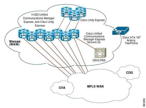
Table 9 lists the hardware and software components used in the Small Campus Multisite H.323 model.
 Feedback