Features and Additional Configurations

After you have completed the basic setup for Mobile and Remote Access, use this chapter to configure features and optional configurations for MRA.

Deployment Partitions

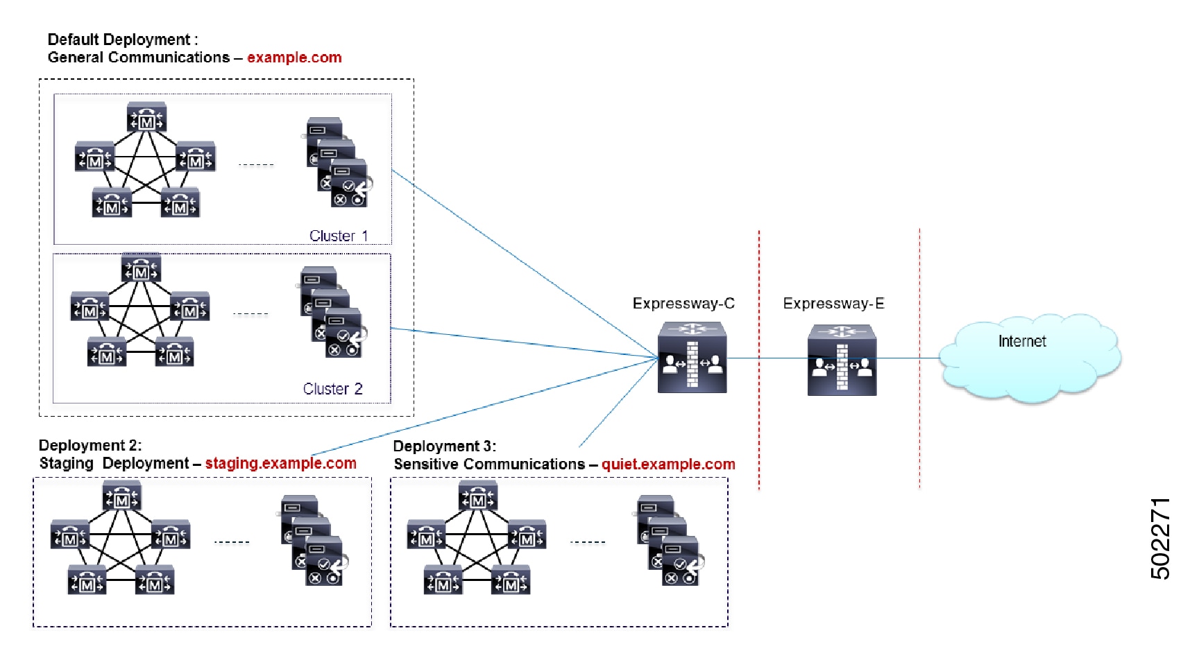
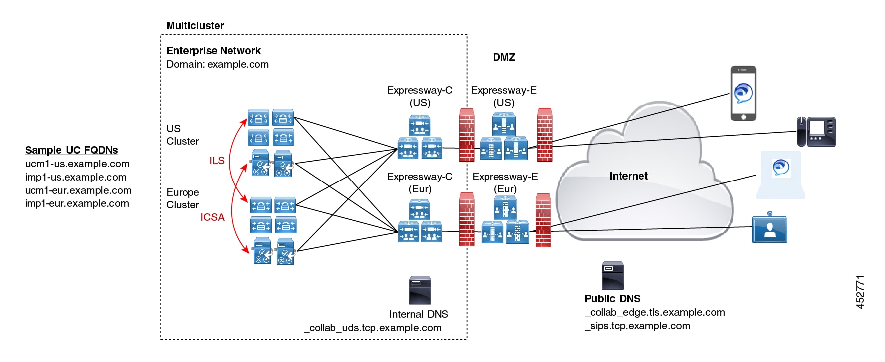
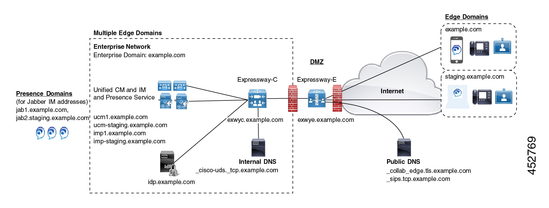
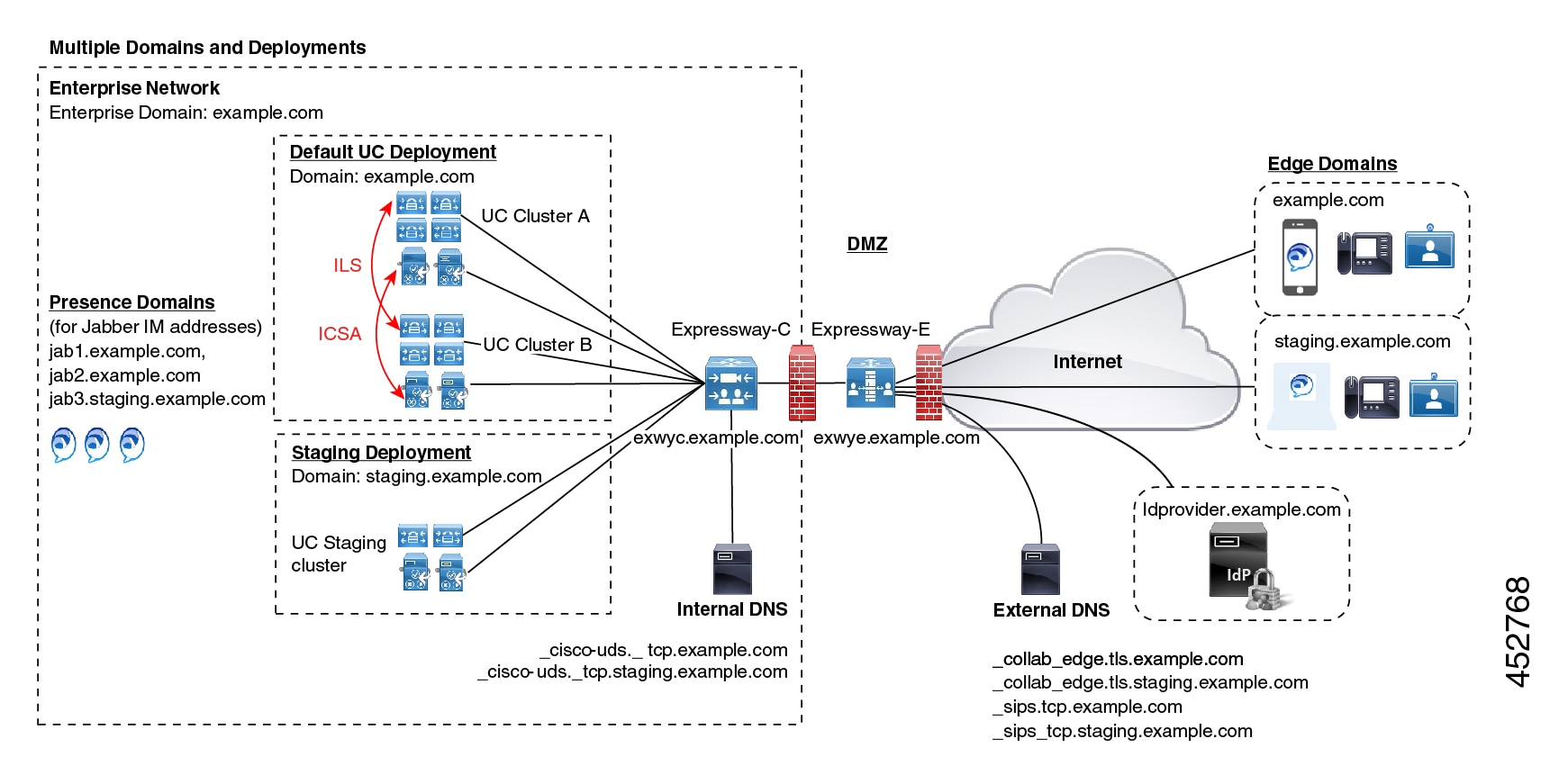
A deployment is an abstract boundary that is used to enclose a domain and one or more Unified Communications service providers (such as Unified CM, Cisco Unity Connection, and IM and Presence Service nodes). The purpose of multiple deployments is to partition the Unified Communications services available to Mobile and Remote Access (MRA) users. So different subsets of MRA users can access different sets of services over the same Expressway pair.

We recommend that you do not exceed ten deployments.

Deployments and their associated domains and services are configured on the Expressway-C.

One primary deployment (called "Default deployment" unless you rename it) automatically encloses all domains and services until you create and populate additional deployments. This primary deployment cannot be deleted, even if it is renamed or has no members.

To partition the services that you provide through Mobile and Remote Access, create as many deployments as you need. Associate a different domain with each one, and then associate the required Unified Communications resources with each deployment.

You cannot associate one domain with more than one deployment. Similarly, each Unified Communications node may only be associated with one deployment.

Example

Consider an implementation of two sets of Unified Communications infrastructure to provide a live MRA environment and a staging environment, respectively. This implementation might also require an isolated environment for sensitive communications, as a third set.

Figure 1. Multiple Deployments to Partition Unified Communications Services Accessed from Outside the Network

Assign Deployment Partitions for UC Services

Use this optional procedure if you have multiple internal UC clusters and you want to partition internal UC services by creating a boundary. One example where this might be useful is if you have a cluster for enterprise UC services and a second staging cluster.

Note

If you don't create any new deployments, then all internal UC applications belong to a single enterprise-wide Default Deployment.

Procedure


Step 1

On Expressway-C, create your deployments:

  1. Go to Configuration > Unified Communications > Deployments and click New.

  2. Create the new deployment.

  3. Repeat for each deployment that want to add.

Step 2

Assign UC domains to your deployments:

  1. Go to Configuration > Domains.

  2. Select the domain that you want to assign.

  3. Select the Deployment that you want to assign to this domain.

  4. Click Save.

  5. Repeat this step to assign deployments to additional domains.

Step 3

Assign UC Services to your Deployments:

  1. Go to Configuration > Unified Communications and select the relevant UC application.

  2. Select the server that you want to assign.

  3. In the Deployment field, select the deployment you want to assign.

  4. Click Save.

  5. Repeat for each node on each UC cluster.


Push Notifications over MRA

If your MRA deployment includes Cisco Jabber or Webex clients that run on iOS or Android devices, you must deploy Push Notifications. Without Push Notifications, your system may not be able to send calls or messages to clients that have entered into background mode.

How Push Notifications Work

When your cluster is enabled for Push Notifications, Cisco Unified Communications Manager and the IM and Presence Service use either the Apple or Google cloud’s Push Notification service to send push notifications for calls and messages to Cisco Jabber or Webex clients that run on iOS or Android devices. Push Notifications let your system communicate with the client, even after it has entered into background mode (also known as suspended mode). Without Push Notifications, the system may not be able to send calls or messages to clients that have entered into background mode.

At startup, mobile and remote Cisco Jabber or Cisco Webex clients that are installed on Android and iOS platform devices register to Cisco Unified Communications Manager and the IM and Presence Service via Expressway-E. So long as the client remains in foreground mode, new calls or messages can be sent to the client via Expressway-E. However, once the client moves to background mode, standard communication channels are unavailable. Push Notifications provides an alternative channel to reach the client via the appropriate partner cloud (Apple or Google).

Push Notifications Requirements

No specific configuration is needed on the Expressway for Push Notifications, assuming Expressway-E is already providing Mobile and Remote Access (MRA) for Jabber iOS devices. However, these prerequisites and recommendations apply:

  • Push Notifications in the Expressway require a network connection between Cisco Jabber and the Push Notification servers in the Apple cloud.

    They cannot work in a private network, with no internet connection.

  • Expressway is already providing Mobile and Remote Access for Jabber for iPhone and iPad. MRA must be fully configured (domain, zone, server settings).

  • Depending on your Unified CM configuration, you may need a forward proxy to send Push Notifications to the Cisco Collaboration Cloud.

  • We recommend using self-describing token authorization.

  • Expressway-E restart required for Push Notifications with instant messages. After you enable Push Notifications on the IM and Presence Service you need to restart the Expressway-E. Until the restart, Expressway-E cannot recognize the push capability on IM and Presence Service and does not send PUSH messages to the Jabber clients.

Configure Push Notifications for MRA

The following requirements exist when deploying Push Notifications over MRA:

  • OAuth token validation must be configured on Expressway.

  • Unified CM must be configured to use a forward proxy server for HTTPS connections to Cisco cloud services.


    Note

    The former built-in forward proxy in Expressway is removed from the product in X12.6.2 and later versions. For earlier Expressway versions, the built-in forward proxy is not supported and should not be used.

For detailed procedures, see Push Notifications Deployment Guide.

Fast Path Registration

Fast Path Registration is available as a Preview feature in X12.7. This feature optimizes routing processes, reducing the server workload, thereby leading to increased capacities. With this feature, Expressway caches the initial routing calculation and then uses a Pre-Routed Route Header to forward subsequent packets to the destination using the cached routing result. This leads to the following benefits:

  • Reduces the routing workload

  • Increases registration capacity

  • Ensures that each media packet follows the same route path

This feature is supported for the following SIP methods: REGISTER

Test Results with Fast Path Registration

The following table displays observed test results for a standalone Expressway pair (Expressway-C + Expressway-E) when this feature is configured. This example assumes the Expressway pair is being used solely for MRA.

Table 1. Test Results with Fast Path Registration

Platform

MRA Registrations

MRA Video Calls

MRA Audio Calls

CE1200

7000

500

1000

Large OVA

3500

500

1000

Medium OVA

3000

150

300

Small OVA

2500

100

200

Small OVA - Business Edition 6000

2500

100

200

Test Results of a cluster with Fast Path Registration

The following table displays observed test results of a cluster with 6 Expressways to provide 4+2 redundancy when this feature is configured. This example assumes the Expressway pair is being used solely for MRA.

Table 2. Test Results of a cluster with Fast Path Registration

Platform

MRA Registrations

MRA Video Calls

MRA Audio Calls

CE1200

28000

2000

4000

Large OVA

14000

2000

4000

Medium OVA

12000

600

1200

Small OVA

10000

400

800

Small OVA - Business Edition 6000

10000

400

800

Configure Fast Path Registration

When Fast Path Registration is enabled, Expressway caches the initial routing calculation and then uses a Pre-Routed Route Header to route subsequent packets using the cached routing result. This feature reduces the server workload, leading to increased capacities.

Procedure


Step 1

On Expressway-E, enable Fast Path Registration by running the Pre-Routed Route Header command, along with a colon-separated list of SIP headers. For example:

xConfiguration SIP PreRoutedRouteHeader: REGISTER

Step 2

On Expressway-E, set both the Digest Cache Interval and Digest Cache Lifetime to 7200 with the following commands:

  • xConfiguration Authentication Remote Digest Cache ExpireCheckInterval "7200"
  • xConfiguration Authentication Remote Digest Cache Lifetime "7200"

Enable SIP Path Headers

The default setting for Expressway-C is to rewrite the Contact header in SIP REGISTER messages. When you enable SIP Path Headers, Expressway-C adds its address into the Path header but does not rewrite the Contact header. This setting is required for some features to work over MRA, including:

  • Shared Lines and Multiple Lines

  • BiB Call Recording

  • Silent Monitoring

  • Key Expansion Modules


Note

It's recommended that you deploy a minimum Unified CM release of 11.5(1)SU4. For details, see CSCvd84831.

Procedure


Step 1

On Expressway-C turn on SIP Path headers:

  1. On Expressway-C go to Configuration > Unified Communications > Configuration.

  2. Set SIP Path headers to On.

  3. Click Save.

Step 2

After saving your settings, refresh Unified CM Servers:

  1. Go to Configuration > Unified Communications > Unified CM Servers.

  2. Click Refresh Servers.


SIP Trunks Between Unified CM and Expressway-C

Expressway deployments for Mobile and Remote Access do not require SIP trunk connections between Unified CM and Expressway-C. Note that the automatically generated neighbor zones between Expressway-C and each discovered Unified CM node are not SIP trunks.

However, you may still configure a SIP trunk if required. (For example, to enable B2B callers or endpoints registered to Expressway to call endpoints registered to Unified CM.)

If a SIP trunk is configured, you must ensure that it uses a different listening port on Unified CM from that used for SIP line registrations to Unified CM. An alarm is raised on Expressway-C if a conflict is detected.

The ports used for SIP trunks are configured on both Unified CM and Expressway.

See Cisco Expressway SIP Trunk to Unified CM Deployment Guide for more information about configuring a SIP trunk.

See Configure OAuth on UC Applications for information on how to configure OAuth-based authorization for SIP trunks.

Configure SIP Ports for Trunk Connections

If you have configured a SIP trunk between Expressway and Cisco Unified Communications Manager, use this procedure to configure the port settings that the trunk uses.

Procedure


Step 1

Configure SIP line registration listening ports on Unified CM:

  1. From Cisco Unified CM Administration, choose System > Cisco Unified CM.

  2. Set the SIP Phone Port to 5060.

  3. Set the SIP Phone Secure Port to 5061.

  4. Click Save.

Step 2

Configure SIP trunk listening ports on Unified CM:

  1. From Cisco Unified CM Administration, choose System > Security > SIP trunk Security Profile.

  2. Click Find and select the profile that you are using for the SIP trunk.

  3. Configure the Incoming Port to be different from the Line ports.

  4. Click Save and then click Apply Config.

Step 3

Configure SIP trunk listening ports on Expressway:

  1. On Expressway-C, go to Configuration > Zones > Zones

  2. Select the Unified CM neighbor zone that is used for the SIP trunk.

  3. Set the SIP Port to the same value as the Incoming Port that was configured in the SIP Trunk Security Profile.

  4. Click Save.


BiB Recording over MRA

The Expressway supports Built-in-Bridge (BiB) recording over MRA. This feature can help organizations to comply with the phone recording requirements of the European Union's Markets in Financial Instruments Directive (MiFID II).

How it Works

  • BiB can be used to record the audio portion of calls that are made or received by users working off-premises.

  • BiB is always enabled on the Expressway.

  • BiB is configurable on Cisco Unified Communications Manager. When BiB is enabled, Unified CM forks the call to and from the endpoint to a media recording server.

Bandwidth and Capacity Requirements

If you plan to use this feature, be aware that it has significant impact on bandwidth and call capacity:

  • It requires additional network bandwidth to be provisioned. Details are provided in the “Capacity Planning for Monitoring and Recording” section of the Cisco Collaboration System 12.x Solution Reference Network Designs (SRND). Enabling BiB for MRA endpoints typically needs double bandwidth as, assuming both sides of the call are recorded, each BiB-enabled call consumes double the usual bandwidth.

  • Enabling BiB on MRA endpoints reduces the overall call capacity of Expressway nodes down to approximately one-third of their original capacity. This is because each call that is being recorded has two additional SIP dialogs associated with it (so essentially equivalent to three calls).

Configuration Requirements

To deploy BiB Recording over MRA, configure the following:

  • BiB Recording must be configured on Cisco Unified Communications Manager. For detailed procedures, see the "Call Recording" chapter of the Feature Configuration Guide for Cisco Unified Communications Manager.

  • SIP Path Headers must be enabled on Expressway. For details, see Enable SIP Path Headers.

In addition, the following requirements must be met:

  • Compatible clients are required:

    • Cisco Jabber for Windows 11.9

    • Cisco Jabber for Mac 11.9

    • Cisco Jabber for iPhone and iPad 11.9

    • Cisco Jabber for Android 11.9

    • Cisco IP Phone 7800 Series, Cisco IP Conference Phone 7832, or Cisco IP Phone 8800 Series devices which support MRA (not all these phones are MRA-compatible)

    • The phones which currently support MRA are listed in the MRA Infrastructure Requirements section of this guide or ask your Cisco representative for details.

  • Registrar/call control agent: Cisco Unified Communications Manager 11.5(1)SU3 BiB is not supported on Expressway-registered endpoints.

  • Edge traversal: Expressway X8.11.1 or later

  • Recording server: Out of scope for this document. (Information about configuring recording for Cisco Unified Communications Manager is available in the Feature Configuration Guide for Cisco Unified Communications Manager.)

HTTP Allow List

The HTTP Allow list is a type of access list for HTTP services. Expressway-C adds both inbound and outbound rules automatically. For example, Expressway adds inbound rules automatically that allow external clients to access the Unified Communications nodes that were discovered during MRA configuration. These include Unified CM nodes (running CallManager and TFTP service), IM and Presence Service nodes, and Cisco Unity Connection nodes.

However, in some cases, you may need to edit the inbound rules to allow certain types of access. You cannot edit outbound rules.

  • To view Inbound rules, go to Configuration > Unified Communications > HTTP allow list > Automatic inbound rules.

  • To view Outbound rules, go to Configuration > Unified Communications > HTTP allow list > Automatic outbound rules.

Editing the HTTP Allow List

You can add your own inbound rules to the HTTP Allow List if remote clients need to access other web services inside the enterprise. For example, these services may require you to configure the allow list:

  • Jabber Update Server

  • Cisco Extension Mobility

  • Directory Photo Host

  • Managed File Transfer

  • Problem Report Tool server

  • Visual Voicemail

<link to Appendix and other places for more info>

You can't add outbound rules to the HTTP Allow List. In addition, you can't edit or delete auto-added rules in the list.


Note

For the Managed File Transfer feature to work across Expressway, make sure that all Unified CM IM and Presence Service nodes appear on the allow list, whether manually or automatically added.

Automatic Inbound Rules

Expressway automatically edits the HTTP allow list when you discover or refresh Unified Communications nodes. This page shows the discovered nodes, and the rules that apply to those nodes.

The first list is Discovered nodes, and contains all the nodes currently known to this Expressway-C. For each node, the list contains the node's address, its type, and the address of its publisher.

The second list is the rules that have been added for you, to control client access to the different types of Unified Communications nodes. For each type of node in your MRA configuration, you'll see one or more rules in this list. They are shown in the same format as the editable rules, but you cannot modify these rules.

Table 3. Properties of Automatically Added Allow List Rules

Column

Description

Type

This rule affects all nodes of the listed type:

  • Unified CM servers: Cisco Unified Communications Manager nodes

  • IM and Presence Service nodes: Cisco Unified Communications Manager IM and Presence Service nodes

  • Unity Connection servers: Cisco Unity Connection nodes

  • TFTP: TFTP nodes

Protocol

The protocol on which the rule allows clients to communicate with these types of nodes.

Ports

The ports on which the rule allows clients to communicate with these types of nodes.

Match type

Exact or Prefix. Depends on the nature of the service the clients access with the help of this rule.

Path

The path to the resource that clients access with the help of this rule. This may not be present or may only be a partial match of the actual resource, if the rule allows Prefix match.

Methods

The HTTP methods that will be allowed through by this rule (such as GET).

Edit the HTTP Allow List

Procedure


Step 1

Go to Configuration > Unified Communications > HTTP allow list > Editable inbound rules to view, create, modify, or delete HTTP allow list rules.

The page has two areas: one for controlling the default HTTP methods, and the other showing the editable rules.

Step 2

(Optional) Use the check boxes to modify the set of default HTTP methods, then click Save.

You can override the defaults while you're editing individual rules. If you want to be as secure as possible, clear all methods from the default set and specify methods on a per rule basis.

When you change the default methods, all rules that you previously created with the default methods will use the new defaults.

Step 3

[Recommended] Delete any rules you don't need by checking the boxes in the left column, then clicking Delete.

Step 4

Click New to create a rule.

Step 5

Configure the rule to your requirements.

Here is some advice for each of the fields.

Table 4. Properties of Manually Added Allow List Rules

Column

Description

Description

Enter a meaningful description for this rule, to help you recognize its purpose.

Url

Specify a URL that MRA clients can access. For example, to allow access to http://www.example.com:8080/resource/path, just type it in exactly like that.

  • The protocol the clients are using to access the host must be http:// or https://

  • Specify a port when using a non-default port, for example, :8080

    (Default ports are 80 (http) and 443 (https))

  • Specify the path to limit the rule scope (more secure), for example, /resource/path

    If you select Prefix match for this rule, you can use a partial path or omit the path. Be aware that this could be a security risk if the target resources are not resilient to malformed URLs.

Allowed methods

Select Use defaults or Choose methods.

If you choose specific HTTP methods for this rule, they will override the defaults you chose for all rules.

Match type

Select Exact match or Prefix match.

Your decision here depends on your environment. It is more secure to use exact matches, but you may need more rules. It is more convenient to use prefix matches, but there is some risk of unintentionally exposing server resources.

Deployment

If you are using multiple deployments for your MRA environment, you also need to choose which deployment uses the new rule. You won't see this field unless you have more than one deployment.

Step 6

Click Create Entry to save the rule and return to the editable allow list.

Step 7

(Optional) Click View/Edit to change the rule.


Upload Rules to the HTTP Allow List


Note

You cannot upload outbound rules.


Procedure


Step 1

Go to Configuration > Unified Communications > HTTP allow list > Upload rules.

Step 2

Browse to and select the CSV file containing your rule definitions.

See Allow List Rules File Reference.

Step 3

Click Upload.

The Expressway responds with a success message and displays the Editable inbound rules page.


Dial via Office Reverse over MRA

Mobile workers need the same high quality, security, and reliability as when they place calls in the office. You can assure them of that when you enable the Dial via Office-Reverse (DVO-R) feature and they are using Cisco Jabber on a dual-mode mobile device. DVO-R routes Cisco Jabber calls through the enterprise automatically.

DVO-R handles call signaling and voice media separately. Call signaling, including the signaling for Mobile and Remote Access on Expressway, traverses the IP connection between the client and Cisco Unified Communications Manager. Voice media traverses the cellular interface and hairpins at the enterprise Public Switched Telephone Network (PSTN) gateway. Moving audio to the cellular interface ensures high-quality calls and securely maintained audio even when the IP connection is lost.

You can configure DVO-R so that, when a user makes a call, the return call from Cisco Unified Communications Manager goes to either:

  • The user’s Mobile Identity (mobile number).

  • An Alternate Number for the user (such as a hotel room).

Call Flow Examples for DVO-R over MRA

The following call flow describes a Dial via Office Reverse over MRA call when you are sending the return call to either a mobile identity or an alternate number. Refer to the subsequent images for illustrations of the call flow.

  1. When you dial a number, a signal is sent to Cisco Unified Communications Manager over the IP path (WLAN or mobile network).

  2. Cisco Unified Communications Manager calls your mobile number or the Alternate Number that you set.

  3. When you answer, Cisco Unified Communications Manager extends the call to the number you dialed, and you hear ring back.

  4. When the person answers, the ongoing call is hairpinned at the enterprise PSTN gateway and the following occurs:

    • With a mobile Identity, your call is anchored at the enterprise gateway. The call is active on your mobile and desk phone, so you can switch between the two.

    • With an alternate number, your ongoing call is not anchored, and you cannot pick up on your desk phone.

Figure 2. DVO-R over MRA with Mobile Identity
Figure 3. DVO-R over MRA with Alternate Number

DVO Requirements

This feature requires the following versions of related systems:

  • Cisco Unified Communications Manager 11.0(1) or later

  • Cisco Jabber 11.1 or later

Additional Notes

  • You can use Dual Tone Multi Frequency-based (DTMF) mid-call features (for example *81 for hold) on anchored calls if there is out-of-band DTMF relay between the PSTN gateway and Cisco Unified Communications Manager. You cannot utilize mid-call features when using an Alternate Number.

  • To prevent the callback leg from Cisco Unified Communications Manager routing to your voicemail—thus stopping the voicemail call going through to the person you are dialing—Cisco recommends that you set your DVO-R voicemail policy to ‘user controlled’. This ensures you must generate a DTMF tone by pressing any key on the keypad before your call can proceed.

Configure Dial via Office-Reverse over MRA

There is no Expressway configuration requirement to make DVO-R work over MRA. However, there is configuration that is required on the Unified CM nodes and Cisco Jabber clients. The high-level configuration is as follows:

Procedure


Step 1

Set up Cisco Unified Communications Manager to support DVO-R.

Step 2

Set up DVO-R for each device.

Step 3

Set up user-controlled voicemail avoidance.

Step 4

Add Remote Destination (optional).

Step 5

Configure Cisco Jabber client settings.


Note

For a detailed configuration example that describes how to configure your UC applications and clients to make Dial via Office-Reverse to work over Mobile and Remote Access, see Configuring Dial via Office-Reverse to Work with Mobile and Remote Access at https://www.cisco.com/c/en/us/support/docs/unified-communications/expressway/200198-Configuring-Dial-via-Office-Reverse-to-W.html.

Multi-cluster Best Practices

This section outlines tips and best practices for configuring multi-cluster MRA Deployments. Following are some Best Practices to keep in mind when configuring multi-cluster MRA deployments:

  • Every Expressway-C cluster must be able to connect to every UC cluster. Otherwise, Expressway-C can’t proxy requests to all the UC clusters. On the primary peer of each Expressway-C cluster, add the publisher node for each UC cluster that Expressway-C must reach and then refresh servers. This will populate Expressway-C with the remaining subscriber nodes from the various UC clusters.

  • If some clusters are sharing SIP domains: you must enable the Home Cluster setting for each user so that each user is assigned to a specific cluster. This setting appears in the End User Configuration window of Cisco Unified Communications Manager.

  • If you have multiple Unified CM clusters within the same domain, the Intercluster Lookup Service (ILS) is recommended, particularly for large intercluster networks. After an initial setup, ILS provides automatic Cluster Discovery and dial plan replication across the ILS network. However, note that ILS is not mandatory as you can configure cluster discovery manually. For details on how to configure an ILS network, see the System Configuration Guide for Cisco Unified Communications Manager.

  • If you have multiple IM and Presence Service clusters within the same domain, you must configure intercluster peering with the Intercluster Sync Agent (ICSA) for the IM and Presence clusters that are in the same domain. For details on how to configure intercluster peering, see the Configuration and Administration Guide for the IM and Presence Service.

  • If you have multiple edge clusters, configure load balancing between them:

    • If those edges are in same datacenter, you can use DNS SRVs for load balancing

    • If the edges are split across geographical boundaries (different cities or even continent), you can use GeoDNS, See below for an example of how to use GeoDNS SRV records to route requests to the appropriate Edge server:

GeoDNS Examples for Multi-cluster

GeoDNS over MRA is supported for the specific purpose of providing the nearest Expressway when the client is relatively distant from the Expressway that is used for MRA. This helps to minimize latency and network delays.

The following example illustrates a multi-cluster deployment with two Expressway-C clusters that connect to multiple Unified CM clusters. This example uses a single domain, but with two geographically displaced Expressway clusters, thereby providing two enterprise edges. Depending on the DNS provider, you can apply GeoDNS to SRV or CNAME record (SRV is preferred if available). Following are two examples of how to use GeoDNS where there are two Edge domains (one Edge in Europe and another in the US).

The preferred SRV approach, if the DNS provider supports it, is to create SRV records with priority settings that are based on the user's location (for example, the US or Europe). The SRV uses the user’s location and the priority setting that is assigned to each Edge server to determine the server to which the request is sent. If that request fails, the other server provides a backup option.

Table 5. GeoDNS in SRV Records (Preferred approach)
SRV Records

User Location

Route to... (priority)

_collab-edge.tls.example.com

_sips_tcp.example.com

US

  • us-expc.example.com (10)

  • eur-expc.example.com (20)

Europe

  • eur-expc.example.com (10)

  • us-expc.example.com (20)

Following is an example of a GeoDNS SRV configuration record that routes to two CNAME aliases (a main alias and a backup CNAME with a lower priority). Each CNAME record routes the call to different servers based on the user location. If the main CNAME fails, the backup CNAME sends the call to a server in a different region (a NA user is routed to a European-based Expressway).

Table 6. GeoDNS routing via CNAME

SRV Records

Route to CNAME (priority)

User Location

Route to...

_collab-edge.tls.example.com

_sips_tcp.example.com

alias1.example.com (10)

US

us-expc.example.com

Europe

eur-expc.example.com

backup-alias1.example.com (20)

US

eur-expc.example.com

Europe

us-expc.example.com


Note

For SRV approach, leave the weight setting in the SRV the same for all records.

Note

You may also need to configure geographically based Calling Search Spaces and partitions on Unified CMso that you can route calls based on the caller’s location. For example, you can create geographically based calling search spaces (a CSS for a specific city) and place all the phones that are in that city within that CSS (one CSS may be called “New_York_CSS” and a different CSS may be called “Chicago_CSS”)

For a more detailed discussion, see “Scaling the Collaboration Edge Solution” in the Preferred Architecture for Cisco Collaboration 12.x Enterprise On-Premises Deployments, CVD at https://www.cisco.com/c/en/us/td/docs/solutions/CVD/Collaboration/enterprise/12x/120/collbcvd/edge.html#pgfId-1081382.


Multidomain Best Practices

This section outlines domain-related information and configuration processes for customers whom want to deploy MRA with multiple domains. The ideal scenario for Mobile and Remote Access is a single domain for all Collaboration applications and endpoints, but this may not be possible in all cases. Depending on your network, a multi-domain setup can have varying levels of complexity, so it’s important to understand the different contexts within which the domain settings can be used.

Multiple Edge Domains

The following image illustrates a basic multi-domain scenario where the internal UC domain is different from the external domain.

Figure 4. Multiple Edge Domains

Note

MRA endpoints must have connectivity to the external public DNS server so that they can reach Expressway-E.

Multiple Domains with Separate Deployments

The following example illustrates a more complex multi-domain scenario where the internal UC environment is split into two Deployments: the Default UC Deployment, which encompasses the main UC applications, including both Expressways and a second Staging deployment. The two deployments are located in different domains. The Default Deployment has multiple UC clusters with ILS and ICSA being used to sync data between the internal clusters. This example also uses a cloud-based Identity Provider that is located in a separate external IdP domain.

Figure 5. Multiple Domains with Separate Deployments

Domain Glossary

The following table outlines the different contexts in which the domain term may be used within an MRA Deployment and how to set them on Expressway. Depending on your deployment, the same domain may be applied for all these contexts.

Table 7. Domain Glossary

Term

Description

Edge domain

This term refers to the remote domain in which remote MRA endpoints connect to the on-premises UC network. This is configured on Expressway-C under the Configuration > Domain menu, and communicated to Expressway-E over the UC Traversal zone

Expressway Server Domain

For both Expressway-C and Expressway-E, the domain is a part of each server’s FQDN address and is provisioned in the System > DNS window on each respective server. Each server supports a single domain only.

Internal UC Domain

This is the domain for internal UC applications such as Cisco Unified Communications Manager and the IM and Presence Service. These applications may be located in the same domain as Expressway or they may be in a different domain.

Note 
If the internal UC applications are in a different domain than Expressway, then you must use FQDNs or IP addresses as server addresses for the UC server addresses. FQDNs are preferred.

Presence Domains

Presence domains are configured on the IM and Presence Service and may be used in the client’s IM address (for example, user@domain).

Note 
For MRA clients, if the Presence Domain is not the same as the Edge domain, add the Presence Domain to the Domain list on Expressway-C.
Note 
Multiple Presence Domains over MRA is supported from Expressway X12.6.3 with IM and Presence Service, Release 10.0(1) or later. However, it's recommended that you do not exceed 75 domains within a single deployment.

MRA Activation Domain

If you are using activation code onboarding of MRA endpoints, the MRA Activation Domain is configured on Unified CM during the cloud onboarding process, representing the domain where MRA endpoints for that cluster must connect for the initial device activation. Each cluster can have a single MRA Activation Domain only.

MRA Service Domain

If you are using activation code onboarding of MRA endpoints, the MRA Service Domain is configured on Unified CM, representing the remote Edge domain where the endpoint connects for normal MRA use. If you have multiple Expressway clusters, the MRA Service Domain lets you specify which Expressway cluster is used for normal MRA operation.

After an MRA device activates within the MRA Activation Domain, the device downloads its configuration file, which contains a redirect to the assigned MRA Service Domain. The device then looks up the _collab_edge SRV for that domain and attempts to register via the Expressway cluster that is assigned to the domain.

MRA Service Domains can be applied to endpoints at the cluster, device pool, or individual device level.

Note 
The MRA Activation domain gets added automatically to the list of available MRA Service Domains for a Unified CM cluster.

Multidomain Configuration Summary

The following table provides a configuration summary of domain-specific tasks for multidomain MRA scenarios.


Note

This summary does not replace the main configuration flow for setting up a basic MRA deployment—you can configure your system to support MRA over multiple domains by following the main configuration flow. However, for complex multidomain scenarios, this summary provides a helpful checklist of domain-specific tasks that you can use to verify that your domain setup is correct.
Table 8. MRA Multidomain Configuration Summary

Steps

Task

Step 1

Configure the Host Name and Domain Name for Expressway servers.

See Set Expressway Server Address.

Step 2

On Expressway-C, add the domains for which MRA registration, call control, provisioning, messaging, and presence services are to be routed to Unified CM. This may include:

  • Internal UC domains

  • Edge domains (if they are different from the internal domains)

  • Presence domains (if they are different from the other domains).

See Add Domains.

Step 3

(Optional). Assign Deployments to internal UC Applications. This optional configuration lets you partition internal UC services. For example, you could use this configuration to partition your main Production cluster off from a separate Staging cluster.

See Assign Deployment Partitions for UC Services.

Step 4

Configure Internal DNS entries:

  1. Configure _cisco-uds._tcp.<domain> SRV records for each Unified CM domain.

  2. Create forward and reverse lookups for each Unified CM and IM and Presence node.

  3. Configure A and PTR records that point Expressway-C to Expressway-E.

Note 
As of X12.6, the _cisco_uds.tcp.example.com internal SRV record is no longer mandatory for MRA endpoints to be able to reach the correct UC cluster. However, note that this SRV record is still required if you are deploying on-premises Cisco Jabber and Webex clients.

See Local DNS (Internal Domains).

Step 5

Configure Public DNS:

  1. On Expressway-E, configure _collab-edge._tls.<domain> and _sips_tcp.<domain> DNS SRV records for each Edge domain.

  2. Configure A records that point the Expressway-E hostname to the public IP address of Expressway-E.

Note 
MRA endpoints must have connectivity to the Public DNS server so that they can reach Expressway-E.

See Public DNS (External Domains).

Warning 

Expressway-E Fully Qualified Domain Name (FQDN) must match with the SRV A record to establish connectivity between MRA endpoints and the Public DNS server so that they can reach Expressway-E.

Step 6

Configure Expressway-E certificates. Make sure that the Expressway-E certificate includes each Unified CM registration domain.

For details, see Certificate Requirements.

Step 7

If you are deploying SAML SSO, associate the appropriate domain to your Identity Provider:

See Associate Domains with an IdP.

Step 8

If you are using Device Activation Codes to provision MRA clients, provision a clusterwide MRA Activation Domain on Unified CM for MRA onboarding.

In addition, provision any MRA Service Domains with the edge domains that you want users to use after their device activates.

See MRA Device Onboarding Configuration Flow.

(Optional) Using SRVs to create Alias FQDNs for Expressway-E

An optional approach if you have multiple Edge domains is to use SRV records to create an alias domain for Expressway-E, which would simulate multiple Expressway-E FQDNs. For example, if you have an Expressway-E server in example.com and you have two edge domains (example.com and staging.com):

  • For each Edge domain, configure the _collab_edge SRV to point to the Expressway-E FQDN address as if it were a part of that Edge domain (for example, an SRV that points to expe.example.com and another that points to expe.staging.com).

  • For each FQDN, configure A records that point to the public IP address of Expressway-E.

Session Persistency

Session Persistency enhances the user experience while roaming and allows Webex apps to do the following:

  • Roam between different Access points in a network.

  • Roam between different networks (For example, Wi-Fi, VPN over 3G/4G) without having to re-register.

  • Maintain the SIP-based subscription status while roaming between different networks.

  • Maintain registration in the case of network connectivity loss.

  • Seamlessly transit both active and held calls from one network to another without call drops.

To facilitate connectivity during roaming between networks, Session Persistency allows dynamic IP address/port change via keep-alive registration. In addition, the feature includes a configurable TCP reconnect timer, which must be enabled at the product level, to allow Webex apps clients to remain connected in case of a temporary network connectivity loss or roaming. The timer is in effect only when the clients tear down the original TCP connection explicitly. To leverage the Session Persistency feature, you must comply with Cisco-defined SIP interfaces.

For example, if you are in an active Webex apps client call inside the office and walk outside the building losing Wi-Fi connectivity, the call would now continue as the client switches to Mobile and Remote Access through Expressway. Likewise, you will not see call drops if the client switches from Mobile and Remote Access through Expressway to the office Wi-Fi network.