Cisco Unified Communications Manager Trunks
Available Languages
Table Of Contents
Cisco Unified Communications Manager Trunks
A Comparison of SIP and H.323 Trunks
General Deployment Considerations
SIP Trunk Features and Operation
SIP Trunks Can Run on All Active Unified CM Nodes
Up to 16 SIP Trunk Destination IP Addresses
SIP Early Offer Support over Cisco Unified CM SIP Trunks
SIP Trunk Message Normalization and Transparency
Route Lists Run on All Active Unified CM Nodes
High Availability for SIP Trunks
Multiple Source Cisco Unified CM Servers for Originating SIP Trunk Calls
Multiple Destination IP Addresses per SIP Trunk
Design Considerations When Using Run on All Active Unified CM Nodes
Multiple SIP Trunks Using Route Lists and Route Groups
Outbound Calls over a Single SIP Trunk
Outbound Calls over Multiple SIP Trunks
SIP Delayed Offer and Early Offer
Calling Party Number Transformation and SIP Trunks
Design Considerations for SIP Trunks
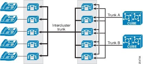
Considerations for SIP Intercluster Trunks
Using Standard Cisco Unified CM Groups with SIP Intercluster Trunks
Using Run on All Active Unified CM Nodes with SIP Intercluster Trunks
Trunk Type and Feature Recommendations for Multi-Cluster Deployments
Multiple Clusters All Running Cisco Unified CM 8.5 or Later Releases
Multiple Clusters Running Cisco Unified CM 8.5 and Prior Releases
Trunk Design Considerations for Clustering over the WAN
Design Guidance for Clustering over the WAN with Leaf Cluster Trunks
Other SIP Trunk Deployment Considerations
General H.323 Intercluster Trunk Deployment Considerations
Basic Operation of H.323 Trunks
Intercluster Trunk (Non-Gatekeeper Controlled)
Intercluster Trunk (Gatekeeper Controlled)
H.225 Trunk (Gatekeeper Controlled)
High Availability for Gatekeeper Controlled Trunks
Load Balancing Outbound Calls over H.323 Gatekeeper Controlled Trunks
H.323 Outbound FastStart Call Connections
H.323 Trunks with Media Termination Points
H.323 Trunk Transport Protocols
H.323 Operation in Cisco Unified CM
Other Design Considerations for H.323 Trunks
General SIP and H.323 Trunk Design Considerations
Deterministic Outbound Call Load Balancing over Cisco Unified CM Trunks
Codec Selection Over IP Trunks
Other Design Considerations for Unified CM Session Management Edition Deployments
Unified CM Session Management Edition and SAF CCD Deployments
Advertising SAF CCD Routes to Leaf Clusters from/through Unified CM Session Management Edition
Advertising SAF CCD Routes from Leaf Clusters to Unified CM Session Management Edition
Operational Considerations for Unified CM Session Management Edition and SAF CCD Deployments
Cisco Unified CM Trunks and Emergency Services
Capacity Planning for Cisco Unified CM IP Trunks
IP PSTN and IP Trunks to Service Provider Networks
Protocol and Media Interworking
Service Provider SIP Trunk Best Practice Recommendations
Design Considerations for Scalability and Redundancy
Management and Monitoring of Service Provider SIP Trunks
Trunk IP-PSTN Connection Models
Cisco Unified Communications Manager Trunks
A trunk is a communications channel on Cisco Unified Communications Manager (Cisco Unified CM) that enables Cisco Unified CM to connect to other servers. Using one or more trunks, Cisco Unified CM can receive or place voice, video, and encrypted calls, exchange real-time event information, and communicate in other ways with call control servers and other external servers.
Trunks are an integral and a crucial part of a Cisco Unified Communications deployment, hence it is important to understand the types of trunks available, their capabilities, and design and deployment considerations such as resiliency, capacity, load balancing, and so forth.
There are two basic types of trunks that can be configured in Cisco Unified CM:
•
SIP and H.323 trunks, both of which can be used for external communications
•
This chapter describes the general capabilities and functions of these trunks:
This chapter discusses the following topics:
•
•
•
A Comparison of SIP and H.323 Trunks
Cisco Unified CM trunk connections support both SIP and H.323. In many cases, the decision to use SIP or H.323 is driven by the unique feature(s) offered by each protocol. There are also a number of external factors that can affect the choice of trunk protocol, such as customer preference or the protocol's maturity and degree of interoperability offered between various vendors' products.
For trunk connections between Cisco devices, this decision is relatively straightforward. For trunk connections to other vendors' products and to service provider networks, it is important to understand which features are required by the customer and the extent of interoperability between any two vendors' products.
Table 2-1 compares some of the features offered over SIP and H.323 trunks between Cisco Unified CM clusters.
Table 2-1 Comparison of SIP and H.323 Features on Cisco Unified Communications Manager Trunks
Calling Line (Number) Identification Presentation
Yes
Yes
Yes
Yes
Calling Line (Number) Identification Restriction
Yes
Yes
Yes
Yes
Calling Name Identification Presentation
Yes
Yes
Yes
Yes
Calling Name Identification Restriction
Yes
Yes
Yes
Yes
Connected Line (Number) Identification Presentation
Yes
Yes
Yes
Yes
Connected Line (Number) Identification Restriction
Yes
Yes
Yes
Yes
Connected Name Identification Presentation
Yes
Yes
Yes
Yes
Connected Name Identification Restriction
Yes
Yes
Yes
Yes
Alerting Name
Yes
Yes
No
Yes
Call Transfer (Blind/Attended)
Yes/Yes
Yes/Yes
Yes/Yes
Yes/Yes
Call Forward All
Yes
Yes
Yes
Yes
Call Forward Busy
Yes
Yes
Yes
Yes
Call Forward No Reply
Yes
Yes
Yes
Yes
Call Completion to Busy Subscriber
No
Yes
No
Yes
Call Completion No Reply
No
Yes
No
Yes
Subscribe/Notify, Publish - Presence
Yes
Yes
No
No
Message Waiting Indication (MWI: lamp ON, lamp OFF)
Yes
Yes
No
Yes
Path Replacement
No
Yes
No
Yes
Call Hold/Resume
Yes
Yes
Yes
Yes
Music On Hold (unicast and multicast)
Yes
Yes
Yes
Yes
DTMF-relay
RFC 2833, KPML (OOB), Unsolicited Notify (OOB)
RFC 2833, KPML (OOB), Unsolicited Notify (OOB)
H.245 Out Of Band (OOB)1
H.245 Out Of Band (OOB)1
SIP Early Offer
Yes - MTP may be required
Yes - MTP may be required
N/A
N/A
SIP Delayed Offer
Yes
Yes
N/A
N/A
H.323 Fast Start
N/A
N/A
Yes - MTP always required for Outbound Fast Start
Yes - MTP always required for Outbound Fast Start
H.323 Slow Start
N/A
N/A
Yes
Yes
Audio codecs
G.711, G.722, G.723, G.729, iLBC, AAC, iSAC
G.711, G.722, G.723, G.729, iLBC, AAC, iSAC
G.711, G.722, G.723, G.729
G.711, G.722, G.723, G.729
Codecs with MTP
All codecs supported when Early Offer support for voice and video calls (insert MTP if needed) is checked
G.711, G.729 when MTP Required is checked
All codecs supported when Early Offer support for voice and video calls (insert MTP if needed) is checked
G.711, G.729 when MTP Required is checked
G.711, G.723, G.729
G.711, G.723, G.729
Video
Yes
Yes
Yes
Yes
Video codecs
H.261, H.263, H.263+, H.264 AVC
H.261, H.263, H.263+, H.264 AVC
H.261, H.263, H.263+, H.264 AVC
H.261, H.263, H.263+, H.264 AVC
T.38 Fax
Yes
Yes
Yes
Yes
Signaling Authentication
Digest, TLS
Digest, TLS
No
No
Signaling Encryption
TLS
TSL
No
No
Media Encryption (audio)
SRTP
SRTP
SRTP
SRTP
RSVP-based QoS and call admission control
Yes
Yes
No
No
Support for + character
Yes
Yes
No
No
Inbound Calls — Called Party: Significant Digits, Prefix-Digits
Yes
Yes
Yes
Yes
Incoming Calling Party Settings: Strip Digits, Prefix-Digits based on Number Type
SIP does not support Number Type - "Unknown" used for all calls
SIP does not support Number Type - "Unknown" used for all calls
Cisco Unified CM, Unknown, National, International, Subscriber
Cisco Unified CM, Unknown, National, International, Subscriber
Incoming Called Party Settings: Strip Digits, Prefix-Digits based on Number Type
N/A
N/A
Cisco Unified CM, Unknown, National, International, Subscriber
Cisco Unified CM, Unknown, National, International, Subscriber
Connected Party Transformation
Yes
Yes
No
No
Outbound Calling Party Transformations
Yes
Yes
Yes
Yes
Outbound Called Party Transformations
Yes
Yes
Yes
Yes
Outbound Calling/Called Party Number Type Setting
SIP does not support Number Type
SIP does not support Number Type
Cisco Unified CM, Unknown, National, International, Subscriber
Cisco Unified CM, Unknown, National, International, Subscriber
Outbound Called/Called Party Numbering Plan Setting
SIP does not support Number Plan
SIP does not support Number Plan
Cisco Unified CM, ISDN, National Standard, Private, Unknown
Cisco Unified CM, ISDN, National Standard, Private, Unknown
Trunk destination — State detection mechanism
OPTIONS Ping
OPTIONS Ping
Per call attempt
Per call attempt
1 H.323 trunks support signaling of RFC 2833 for certain connection types.
SIP Trunks Overview
SIP trunks on Cisco Unified CM/Unified CM Session Management Edition can be used for two different purposes:
•
•
Today, SIP is arguably the most commonly chosen protocol when connecting to service providers and Unified Communications applications. Cisco Unified CM 8.5 and later releases provide the following SIP trunk and call routing enhancements:
•
•
•
•
•
•
•
The SIP trunk features available in the 8.5 release make SIP the preferred choice for new and existing trunk connections. The QSIG over SIP feature provides parity with H.323 intercluster trunks and can also be used to provide QSIG over SIP trunk connections to Cisco IOS gateways (and on to QSIG-based TDM PBXs). The ability to run on all Cisco Unified CM nodes and to handle up to 16 destination IP addresses improves outbound call distribution from Cisco Unified CM clusters and reduces the number of SIP trunks required between clusters and devices. SIP OPTIONS ping provides dynamic reachability detection for SIP trunk destinations, rather than per-call reachability determination. SIP Early Offer support for voice and video calls (insert MTP if needed) can reduce or eliminate the need to use MTPs and allows voice, video, and encrypted calls to be made over SIP Early Offer trunks.
SIP trunk normalization and transparency improve native Cisco Unified CM interoperability with and between third-party unified communications systems. Normalization allows inbound and outbound SIP messages and SDP information to be modified on a per-SIP-trunk basis. Transparency allows Cisco Unified CM to pass SIP headers, parameters, and content bodies from one SIP trunk call leg to another, even if Cisco Unified CM does not understand or support the parts of the message that are being passed through.
These features are discussed in detail later in this section.
For the complete list of new enhancements for SIP trunks, refer to the New and Changed for Cisco Unified Communications Manager 8.5(1) document available at
http://www.cisco.com/en/US/products/sw/voicesw/ps556/prod_release_notes_list.html
General Deployment Considerations
Cisco Unified CM SIP trunks offer a greater set of features in comparison with H.323 intercluster trunks, thus making SIP the protocol of choice for intercluster trunk connections (although H.323 Annex M1 may still be preferred for intercluster trunk connections to Cisco Unified CM clusters using earlier software versions). Also, given the wide support of SIP in the industry, SIP trunks are usually a good choice for connectivity to third-party applications and service providers.
SIP Trunk Features and Operation
This section explains how Cisco Unified CM SIP trunks operate and describes several key SIP trunk features that should be taken into account when designing and deploying Cisco Unified CM SIP trunks.
SIP Trunks Can Run on All Active Unified CM Nodes
When the Run on all Active Unified CM Nodes option is checked on a SIP trunk, Cisco Unified CM creates an instance of the SIP trunk daemon on every call processing subscriber within the cluster, thus allowing SIP trunk calls to be made or received on any call processing subscriber. (Prior to this feature, up to three nodes could be selected per trunk by using Cisco Unified CM Groups.) With Run on all Active Unified CM Nodes enabled, outbound SIP trunk calls originate from the same node on which the inbound call (for example, from a phone or trunk) is received. As with all Cisco Unified CM SIP trunks, the SIP daemons associated with the trunk will accept inbound calls only from end systems with IP addresses that are defined in the trunk's destination address fields. Running SIP trunks on all nodes is recommended where the SIP trunk is required to process a large number of calls so that outbound and inbound call distribution can be evenly spread across all call processing subscribers within a cluster. Also, when multiple SIP trunks to the same destination(s) are using the same subscriber, a unique incoming and destination port number must be defined per trunk to allow each trunk to be identified uniquely.
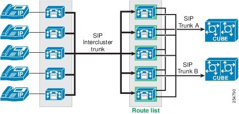
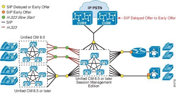
Up to 16 SIP Trunk Destination IP Addresses
SIP trunks can be configured with up to 16 destination IP addresses, 16 fully qualified domain names, or a single DNS SRV entry. Support for additional destination IP addresses reduces the need to create multiple trunks associated with route lists and route groups for call distribution between two Unified Communications systems, thus simplifying Cisco Unified CM trunk design. (See Figure 2-1.) This feature can be used in conjunction with the Run on all Active Unified CM Nodes feature or with a SIP trunk that uses standard Cisco Unified CM Groups to create a SIP daemon on up to three nodes within the cluster. Bear in mind, however, that the SIP daemons associated with a Cisco Unified CM SIP trunk will accept inbound calls only from end systems with IP addresses that are defined in the trunk's destination address fields.
Figure 2-1 SIP Trunks with Multiple Destination IP Addresses Running on All Active Nodes
SIP OPTIONS Ping
The SIP OPTIONS Ping feature can be enabled on the SIP Profile associated with a SIP trunk to dynamically track the state of the trunk's destination(s). When this feature is enabled, each node running the trunk's SIP daemon will periodically send an OPTIONS Request to each of the trunk's destination IP addresses to determine its reachability and will send calls only to reachable nodes. A destination address is considered to be "out of service" if it fails to respond to an OPTIONS Request, if it sends a Service Unavailable (503) response or Request Timeout (408) response, or if a TCP connection cannot be established. The trunk state is considered to be "in service" when at least one node receives a response (other than a 408 or 503) from a least one destination address. SIP trunk nodes can send OPTIONS Requests to the trunk's configured destination IP addresses or to the resolved IP addresses of the trunk's DNS SRV entry. Enabling SIP OPTIONS Ping is recommended for all SIP trunks because it allows Cisco Unified CM to dynamically track trunk state rather than determining trunk state on a per-call and timeout basis.
SIP Early Offer Support over Cisco Unified CM SIP Trunks
SIP negotiates media exchange by means of the Session Description Protocol (SDP), where one side offers a set of capabilities to which the other side answers, thus converging on a set of media characteristics. SIP allows the initial offer to be sent either by the caller in the initial INVITE message (Early Offer) or, if the caller chooses not to, the called party can send the initial offer in the first reliable response (Delayed Offer).
By default, Cisco Unified CM SIP trunks send the INVITE without an initial offer (Delayed Offer). Cisco Unified CM has two configurable options to enable a SIP trunk to send the offer in the INVITE (Early Offer):
•
•
Media Termination Point Required
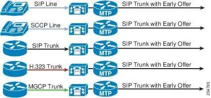
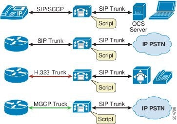
Enabling the Media Termination Point Required option on the SIP trunk assigns an MTP from the trunk's media resources group (MRG) to every outbound call. (See Figure 2-2.) This statically assigned MTP supports only the G.711 or G.729 codecs, thus limiting media to voice calls only.
Figure 2-2 SIP Early Offer with Media Termination Point Required
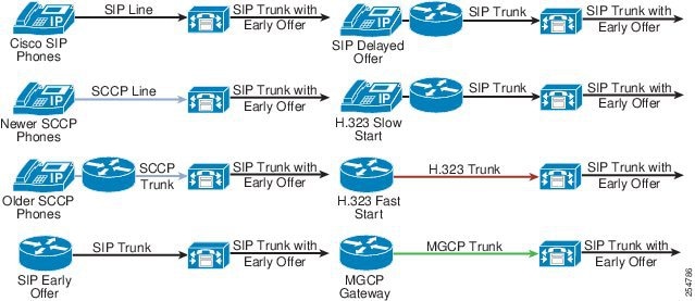
Early Offer Support for Voice and Video Calls (Insert MTP If Needed)
Enabling Early Offer support for voice and video calls (insert MTP if needed) on the SIP Profile associated with the SIP trunk inserts an MTP only if the calling device cannot provide Cisco Unified CM with the media characteristics required to create the Early Offer. In general, Early Offer support for voice and video calls (insert MTP if needed) is recommended because this configuration option reduces MTP usage (see Figure 2-3). Calls from older SCCP-based phones registered to Cisco Unified CM over SIP Early Offer trunks configured with this option will use an MTP to create the Offer SDP, and these calls support voice, video, and encrypted media (see Endpoint Features Summary, page 19-50). Inbound calls to Cisco Unified CM from SIP Delayed Offer trunks or H.323 Slow Start trunks that are extended over an outbound SIP Early Offer trunk will use an MTP to create the Offer SDP; however, these calls support audio only in the initial call set up but can be escalated mid-call to support video and SRTP if the call media is renegotiated (for example, after hold/resume). For guidance on when to use Early Offer support for voice and video calls (insert MTP if needed), see Design Considerations for SIP Trunks.

Note
Figure 2-3 Early Offer Support for Voice and Video Calls
Cisco Unified CM does not need to insert an MTP to create an outbound Early Offer call over a SIP trunk if the inbound call to Cisco Unified CM is received by any of the following means:
•
•
•
•
•
For the above devices, Cisco Unified CM uses the media capabilities of the endpoint and applies the codec filtering rules based on the region-pair of the calling device and outgoing SIP trunk to create the offer SDP for the outbound SIP trunk. In most cases, the offer SDP will have the IP address and port number of the endpoint initiating the call. This is assuming that Cisco Unified CM does not have to insert an MTP for other reasons such as a DTMF mismatch, TRP requirements, or a transcoder requirement when there is no common codec between the regions of the calling device and the SIP trunk.
When Early Offer support for voice and video calls (insert MTP if needed) is configured on a trunk's SIP Profile, calls from older SCCP-based phones (see Endpoint Features Summary, page 19-50), SIP Delayed Offer trunks, and H.323 Slow Start trunks will cause Cisco Unified CM to allocate an MTP if an MTP or transcoder has not already been allocated for that call for another reason. The MTP is used to generate an offer SDP with a valid media port and IP address. The MTP will be allocated from the media resources associated with the calling device rather than from the outbound SIP trunk's media resources. (This prevents the media path from being anchored to the outbound SIP trunk's MTP). If the MTP cannot be allocated from the calling device's media resource group list (MRGL), then the MTP allocation is attempted from the SIP trunk's MRGL.
For calls from older SCCP phones (see Endpoint Features Summary, page 19-50) registered to Cisco Unified CM, some of the media capabilities of the calling device (for example, supported voice codecs, video codecs, and encryption keys if supported) are available for media exchange through the Session Description Protocol (SDP). Cisco Unified CM will create a superset of the endpoint and MTP codec capabilities and apply the codec filtering based on the applicable region-pair settings. The outbound Offer SDP will use the MTP's IP address and port number and can support voice, video, and encrypted media. Note that the MTP should be configured to support the pass-through codec.
When Cisco Unified CM receives an inbound call on an H.323 Slow Start or SIP Delayed Offer trunk, the media capabilities of the calling device are not available when the call is initiated. In this case, Cisco Unified CM must insert an MTP and will use its IP address and UDP port number to advertise all supported audio codecs (after region pair filtering) in the Offer SDP of the initial INVITE sent over the outbound SIP trunk. When the Answer SDP is received on the SIP trunk, if it contains a codec that is supported by the calling endpoint, then no additional offer-answer transaction is needed. In case of codec mismatch, Cisco Unified CM can either insert a transcoder to address the mismatch or send a reINVITE or UPDATE to trigger media negotiation. Calls from H.323 Slow Start or SIP Delayed Offer trunks support audio only in the initial call setup, but they can be escalated mid-call to support video and SRTP if the call media is renegotiated (for example, after Hold/Resume).
QSIG over SIP Trunks
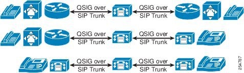
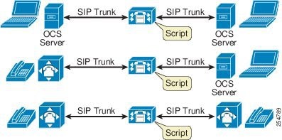
Cisco Unified CM can encapsulate QSIG content in SIP messages, thus allowing features such as Call Back, MWI, and Path Replacement to be invoked over SIP QSIG intercluster trunks and over SIP QSIG trunks to Cisco IOS gateways. (See Figure 2-4.) QSIG over SIP trunks provides parity with the QSIG feature set on H.323 Annex M1 intercluster trunks and MGCP QSIG trunks. (ISO and ECMA variants of QSIG are supported on a per-trunk basis.)
Figure 2-4 QSIG over SIP Trunks
SIP Trunk Message Normalization and Transparency
Normalization and transparency provide powerful script-based functionality for SIP trunks that can be used to transparently forward and/or modify SIP messages and message body contents as they traverse Cisco Unified CM. Normalization and transparency scripts are designed to address SIP interoperability issues, allowing Cisco Unified CM to interoperate with SIP-based third-party PBXs, applications, and IP PSTN services.
SIP Trunk Normalization
Normalization allows incoming and outgoing SIP messages to be modified on their way through Cisco Unified CM. Normalization applies to all calls that traverse a SIP trunk with an associated script, regardless of what protocol is being used for the other endpoint involved in the call. For example, a SIP trunk normalization script can operate on a call from a SIP line device to a SIP trunk, from an SCCP-based device to a SIP trunk, from MGCP to SIP trunk, from H.323 to SIP trunk, and so forth. (See Figure 2-5.) Normalization does not require end-to-end SIP.
Figure 2-5 SIP Trunk Normalization
SIP Trunk Transparency
Transparency allows Cisco Unified CM to pass SIP headers, parameters, and content bodies from one SIP trunk call leg to another, even if Cisco Unified CM does not understand or support the parts of the message that are being passed through. Transparency (or transparent pass-through) is applicable only when the call through Cisco Unified CM is from SIP trunk to SIP trunk, as illustrated in Figure 2-6.
Figure 2-6 SIP Trunk Transparency
Normalization and transparency scripts use Lua, a powerful, fast, lightweight, embeddable scripting language to modify SIP messages and SDP body content on SIP trunks. (For more information on Lua, refer to the documentation available at http://lua-users.org/wiki/LuaOrgGuide.)
Cisco has created a library of Lua-based SIP Message APIs that allow specified information in the SIP message and SDP body to be retrieved, modified, replaced, removed, passed through, ignored, appended to, transformed, and so on. The underlying Lua language allows retrieved information to be stored as variables and operated on using a series of operations such as: If, elseif, while, do, <, >, =, and so forth. The scripting approach naturally supports multiple variables and state-specific contexts for making script decisions. The combination of Cisco's SIP Message Library APIs and the functionality underlying the Lua language creates a very powerful scripting environment that allows almost any SIP message and/or its SDP body content to be modified.
For inbound messages on a SIP trunk, normalization and transparency script processing occurs immediately after receiving the message from the network. For outbound messages, script processing occurs immediately before sending the message to the network.
Within a Lua script, callback functions (also known as message handlers) are used to request message types of interest. The Cisco Lua environment constructs the name of the message handler based on the message direction and method for requests (for example, inbound_INVITE) and based on the message direction, response code, and method (from the CSeq header) for responses (for example, outbound_180_INVITE). A message object (for example, msg) is passed to the message handler, thereby allowing the script to modify the message (for example, inbound_INVITE(msg)).
Callback Function (message Handler) examples:
inbound_INVITE()
outbound_INVITE()
inbound_UPDATE()
outbound_SUBSCRIBE()
inbound_3XX_INVITE()
outbound_180_INVITE()
The Lua script then uses APIs defined in the Cisco SIP Message library to access and manipulate message parameters. For example:
•
•
•
•
•
•
•
•
•
The following examples illustrate the use of SIP Message API scripts.
Example 2-1 SIP Message API — getRequestLine
getRequestLine() returns the method, request-uri, and version.
This method returns three values:
•
•
•
Example script:
Line 1
M = {}
Line 2
function M.outbound_INVITE(message)
Line 3
local method, ruri, ver = message:getRequestLine()
Line 4
end
Line 5
return M
Line 1 initializes the set of callback functions to an empty value. This set of callback functions, named M, is essentially a Lua table.
Lines 2 to 4 define a message handler. This callback function is executed when an outbound INVITE is sent from Cisco Unified CM. The script then gets the method, request-uri, and version from the request line and stores these values.
The script can define multiple message handlers. The name of the message handler dictates which message handler is invoked (if any) for a given SIP message.
The last line returns the set of callbacks. This line is absolutely required.
Message:
INVITE sip:1234@10.10.10.1 SIP/2.0Output and result:
method == "INVITE"ruri == "sip:1234@10.10.10.1"version == "SIP/2.0"Example 2-2 A script that simply removes the "Cisco-Guid" header in an outbound INVITE
Line 1
M = {}
Line 2
function M.outbound_INVITE(message)
Line 3
message:removeHeader("Cisco-Guid")
Line 4
end
Line 5
return M
Line 1 initializes the set of callback functions to an empty value. This set of callback functions, named M, is essentially a Lua Table.
Lines 2 to 4 define a message handler. This callback function is executed when an outbound INVITE is sent from Cisco Unified CM. The script can define multiple message handlers. The name of the message handler dictates which message handler is invoked (if any) for a given SIP message.
The last line returns the set of callbacks. This line is absolutely required.
Message:
INVITE sip:1234@10.10.10.1 SIP/2.0.P-Asserted-Identity: "1234" <1234@10.10.10.1>Cisco-Guid: 1234-4567-1234Session-Expires: 1800Output and results:
INVITE sip:1234@10.10.10.1 SIP/2.0.P-Asserted-Identity: "1234"For more information on SIP trunk normalization and transparency scripts, refer to the Developer Guide for SIP Transparency and Normalization, available at
http://www.cisco.com/en/US/docs/voice_ip_comm/cucm/sip_tn/8_5_1/sip_t_n.html
Route Lists Run on All Active Unified CM Nodes
Although this is not specifically a SIP trunk feature, running route lists on all nodes provides benefits for trunks in route lists and route groups. Running route lists on all nodes improves outbound call distribution by using the "route local" rule to avoid unnecessary intra-cluster traffic.
For route lists, the route local rule operates as follows:
For outbound calls that use route lists (and associated route groups and trunks), when a call from a registered phone or inbound trunk arrives at the node with the route list instance, Cisco Unified CM checks to see if an instance of the selected outbound trunk exists on the same node as the route list. If so, Cisco Unified CM will use this node to establish the outbound trunk call.
If both the route list and the trunk have Run on all Active Unified CM Nodes enabled, outbound call distribution will be determined by the node on which the inbound call arrives. When the selected outbound trunk uses Cisco Unified CM Groups instead of running on all nodes, Cisco Unified CM will apply the route local rule if an instance of the selected outbound trunk exists on the same node on which the inbound call arrived. If an instance of the trunk does not exist on this node, then Cisco Unified CM will forward the call (within the cluster) to a node where the trunk is active.
If the route list does not have Run on all Active Unified CM Nodes enabled, an instance of the route list will be active on one node within the cluster (the primary node of the trunk's Cisco Unified CM Group) and the route local rule will be applied on this node.
As a general recommendation, Run on all Active Unified CM Nodes should be enabled for all route lists. (See Figure 2-7.)
Figure 2-7 Route Lists Running on All Active Unified CM Nodes
SIP Trunks Using DNS
Using a DNS SRV entry as the destination of a SIP trunk might be preferable to defining multiple destination IP addresses in certain situations such as the following:
•
•
•
•
Note
Figure 2-8 shows the call flow for a SIP trunk using DNS SRV to resolve the addresses to a destination Cisco Unified CM cluster. However, this destination could also be a third-party unified communications system.
Figure 2-8 Call Flow for Intercluster SIP Trunk Using DNS SRV
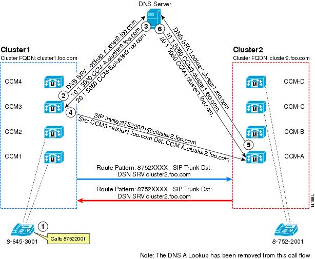
Figure 2-8 illustrates the following steps in the call flow:
1.
2.
3.
4.
5.
6.
High Availability for SIP Trunks
A variety of Cisco Unified CM options is available for configuring high availability with SIP trunks, all of which can be combined to provided redundancy and resiliency for both the source and destination servers of SIP trunks. These options can be categorized as follows:
•
•
•
Multiple Source Cisco Unified CM Servers for Originating SIP Trunk Calls
Using Standard Cisco Unified CM Groups
The nodes defined in the Cisco Unified CM Group associated with an individual trunk make up the set of servers that can place or receive calls over that trunk. Up to three nodes can be defined in a Cisco Unified CM Group, thus ensuring high availability of the trunk itself.
Using Run on All Active Unified CM Nodes
The Run on all Active Unified CM Nodes feature creates and enables a SIP trunk instance on each call processing subscriber within the cluster, thus allowing these nodes to place or receive calls over the trunk.
The Cisco Unified CM Route Local Feature And Its Effect of Subscriber Selection for Outbound SIP Trunk Calls
The Route Local feature in Cisco Unified CM is designed to reduce intra-cluster traffic. The feature operates as illustrated by the following example:
When a device such as a phone is making an outbound call over SIP Trunk 1, if an instance of SIP Trunk 1 is active on the same node as the one to which the phone is registered, then always use this co-located SIP Trunk 1 instance rather than internally routing the call to another SIP Trunk 1 instance on another node within the cluster.
The effect of the Route Local feature on node selection depends on whether Cisco Unified CM Groups or Run on all Active Unified CM Nodes is configured on the trunk. For trunks with Run on all Active Unified CM Nodes configured, the node to which the calling device is registered is used to make the outbound SIP trunk call. When Cisco Unified CM Groups are used on the trunk, if the calling device is registered to one of the nodes in the trunk's Cisco Unified CM Group, then the Route Local rule applies. If the calling device is not registered to one of the nodes in the trunk's Cisco Unified CM Group, then Cisco Unified CM will randomly distribute the call over the nodes in the trunk's Cisco Unified CM Group.
Using Run on all Active Unified CM Nodes is the recommended approach for SIP trunks because it allows call distribution across nodes to be determined by the calling device and it minimizes intra-cluster traffic.
Multiple Destination IP Addresses per SIP Trunk
A single SIP trunk can be configured with up to 16 destination IP addresses. Cisco Unified CM uses random distribution to the configured destination IP addresses when placing calls over a SIP trunk. Using multiple IP addresses on a SIP trunk can help to reduce the need to deploy multiple trunks with route lists and route groups.
Design Considerations When Using Run on All Active Unified CM Nodes
When using Run on All Active Unified CM Nodes in conjunction with multiple destination addresses, be aware that to accept inbound calls, the inbound source IP address received on the SIP trunk must match with a configured destination IP address on the inbound trunk. For example, if Run on all Active Unified CM Nodes is configured on the SIP intercluster trunk in each cluster, then each trunk must be configured with the corresponding destination address of every active node in the destination cluster. Where clustering over the WAN designs are deployed and geographic call distribution and failover are required, use standard Cisco Unified CM Groups on multiple intercluster trunks (each with up to three destination IP addresses) in conjunction with route lists and route groups.
Multiple SIP Trunks Using Route Lists and Route Groups
Multiple prioritized SIP trunks are often required to address failure scenarios in Unified Communications designs. These trunks should be configured in route groups in a single route list and associated with a route pattern. If Cisco Unified CM is not able to place a call over the selected trunk in the list, it will try the next trunk in the list. As a general recommendation, enable Run on all Active Unified CM Nodes for all route lists.
SIP OPTIONS Ping
SIP OPTIONS Ping can be enabled on the SIP Profile associated with a SIP trunk to dynamically track the state of the trunk's destination(s). When this option is enabled, each node running the trunk's SIP daemon will periodically send an OPTIONS Request to each of the trunk's destination IP addresses to determine its reachability. Enabling SIP OPTIONS Ping is recommended for all SIP trunks that require high availability because it allows Cisco Unified CM to dynamically track trunk state rather than determining trunk state on a per-call and timeout basis.
Load Balancing for SIP Trunks
When designing load balancing for SIP trunks, consider both the node that sources the call and its destination. With Cisco Unified CM SIP trunks, the node used to originate the call is determined by the Route Local rule, the number of nodes on which the outbound trunk is active, and whether a route list is used in conjunction with multiple outbound trunks. These considerations are discussed in the following sections.
Outbound Calls over a Single SIP Trunk
A single SIP trunk can run on up to three Cisco Unified CM nodes in a Cisco Unified CM Group, or it can run on all active Cisco Unified CM nodes in the cluster. To select the source node for outbound calls, Cisco Unified CM applies the following decision processes:
•
•
Outbound Calls over Multiple SIP Trunks
Because SIP trunks can run on all active Cisco Unified CM nodes and have up to 16 destination addresses, multiple SIP trunks typically do not need to be used to provide even call distribution between two Unified Communications systems. Where multiple trunks are used with route lists and route groups, route lists should be enabled to run on all active Cisco Unified CM nodes. Multiple SIP trunks are often used in conjunction with route lists to provide failover to the PSTN or to a group of Cisco Unified CM servers in a different site as part of a cluster deployed over the WAN. The selection of the Cisco Unified CM node used to initiate an outbound SIP trunk call, and the distribution of calls over the trunk's configured destination IP addresses, are determined in the same way as described for single trunks. Where clustering over the WAN designs are deployed and geographic call distribution and failover are required, use multiple intercluster trunks (each with up to three destination IP addresses) with standard Cisco Unified CM Groups in conjunction with route lists and route groups.
SIP OPTIONS Ping
Use OPTIONS Ping to dynamically track the state of each destination IP address on each SIP trunk and the collective state of the trunk as a whole. If a destination address is unreachable, Cisco Unified CM will not extend calls to this device. When all destinations are unreachable, the SIP trunk is considered to be out-of-service.
SIP Delayed Offer and Early Offer
Cisco Unified CM uses the SIP Offer/Answer model for establishing SIP sessions, as defined in RFC 3264. In this context, an Offer is contained in the Session Description Protocol (SDP) fields sent in the body of a SIP message. The Offer typically defines the media characteristics supported by the device (media streams, codecs, directional attributes, IP address, and ports to use). The device receiving the Offer sends an Answer in the SDP fields of its SIP response, with its corresponding matching media streams and codec, whether accepted or not, and the IP address and port on which it wants to receive the media streams. Cisco Unified CM uses this Offer/Answer model to establish SIP sessions as defined in the key SIP standard, RFC 3261.
RFC 3261 defines two ways that SDP messages can be sent in the Offer and Answer. These methods are commonly known as Delayed Offer and Early Offer, and support for both methods by User Agent Client/Servers is a mandatory requirement of the specification. In the simplest terms, an initial SIP Invite sent with SDP in the message body defines an Early Offer, whereas an initial SIP Invite without SDP in the message body defines a Delayed Offer.
In an Early Offer, the session initiator (calling device) sends its capabilities (for example, codecs supported) in the SDP contained in the initial Invite (thus allowing the called device to choose its preferred codec for the session). In a Delayed Offer, the session initiator does not send its capabilities in the initial Invite but waits for the called device to send its capabilities first (for example, the list of codecs supported by the called device, thus allowing the calling device to choose the codec to be used for the session).
Delayed Offer and Early Offer are the two options available to all standards-based SIP switches for media capabilities exchange. Most vendors have a preference for either Delayed Offer or Early Offer, each of which has its own set of benefits and limitations.
Note
Early Media
In certain circumstances, a SIP session might require that a media path be set up prior to the finalization of the media capabilities exchange between the two SIP endpoints. To this end, the SIP protocol allows the establishment of Early Media after the initial Offer has been received by an endpoint. Some reasons for using Early Media include:
•
•
Cisco Unified CM supports Early Media for both Early Offer and Delayed Offer calls.
For a SIP trunk to support Early Media cut-through, you must enable PRACK through the SIP Rel1XX Options feature in the SIP Profile associate with the trunk.
Note
Media Termination Points
MTPs are used by Cisco Unified CM for the following purposes:
•
•
•
•
Either of the following methods can be used to enable Early Offer on SIP trunks:
•
In this case an MTP is used for every outbound call, and only voice calls using a single codec are supported.
•
With this method an MTP is inserted only if the calling device or trunk cannot send all of the information about its media capabilities in the initial SIP Invite (for example, an inbound call to Cisco Unified CM from a SIP Delayed Offer or H.323 Slow Start trunk). In this case, when an MTP is used, additional voice codecs can be supported in the initial call setup by using the MTP's pass-through codec. Once established, this audio call can be escalated to support video and encryption if the call's media is renegotiated (for example, after hold/resume). When an MTP is not needed, all calls support voice, video, and encrypted media.
Cisco Unified CM SIP Delayed Offer and Early Offer Recommendations
Cisco Unified CM SIP trunks support Delayed Offer (Invite without SDP) by default. Media termination points (MTPs) are generally not required for Delayed Offer calls from Cisco Unified CM SIP trunks and therefore voice, video, and encrypted calls are all supported. Cisco recommends Delayed Offer as the call setup method for outbound calls from Cisco Unified CM SIP trunks.
In cases where SIP Early Offer is required on Cisco Unified CM SIP trunks, Early Offer support for voice and video calls (insert MTP if needed) is recommended because fewer MTP resources are required in comparison with MTP Required. When MTPs are used in these cases, they can provide support for voice, video, and encrypted media.
For calls inbound and outbound from Cisco Unified CM, endpoints can negotiate the use of RFC 2833 or an out-of-band DTMF method (for example, KPML) end-to-end. If a common DTMF method cannot be negotiated between the endpoints, Cisco Unified CM will insert an MTP dynamically.
MTPs are available in three forms:
•
•
•
In general, Cisco IOS MTPs are recommended over Cisco Unified CM MTPs because Cisco IOS MTPs provide additional functionality such as support for additional codec types and the pass-through codec.
The following example configuration is for a Cisco IOS software-based MTP:
!sccp local Vlan5sccp ccm 10.10.5.1 identifier 5 version 5.0.1! Communications Manager IP address (10.10.5.1)sccp!sccp ccm group 5bind interface Vlan5associate ccm 5 priority 1associate profile 5 register MTP000E83783C50! MTP name (MTP000E83783C50) ... must match the Unified CM MTP name.!dspfarm profile 5 mtpdescription software MTPcodec g711ulawcodec pass-throughmaximum sessions software 500associate application SCCPDTMF Transport
There are several methods of transporting DTMF information between SIP endpoints. In general terms, these methods can be classified as out-of-band (OOB) and in-band signaling. In-band DTMF transport methods send either raw or signaled DTMF tones within the RTP stream, and they need to be handled and interpreted by the endpoints that generate and/or receive them. Out-of-band signaling methods transport DTMF tones outside of the RTP path, either directly to and from the endpoints or through a call agent such as Cisco Unified CM, which interprets and/or forwards these tones as required.
Out-of-band (OOB) SIP DTMF signaling methods include Unsolicited Notify (UN), Information (INFO), and Key Press Markup Language (KPML). While KPML (RFC 4730) is the OOB signaling method preferred by Cisco, KPML is not widely used in the market place at this time. Currently, the only known products supporting KPML are Cisco Unified CM, Cisco IOS Gateways (Release 12.4 and later), and some models of Cisco IP Phones. INFO is not supported by Cisco Unified CM.
In-band DTMF transport methods send DTMF tones as either raw tones in the RTP media stream or as signaled tones in the RTP payload using RFC 2833. Among SIP product vendors, RFC 2833 has become the predominant method of sending and receiving DTMF tones and is supported by the majority of Cisco voice products.
Because in-band signaling methods send DTMF tones in the RTP media stream, the SIP endpoints in a session must either support the transport method used (for example, RFC 2833) or provide a method of intercepting this in-band signaling and converting it. If the two endpoints are using a back-to-back user agent (B2BUA) server for the call control (for example, Cisco Unified CM) and the endpoints negotiate different DTMF methods between each device and call control box, then the call agent determines how to handle the DTMF differences, either through MTP insertion or by OOB methods. With Cisco Unified CM, a DTMF transport mismatch (for example, in-band to out-of-band DTMF) is resolved by inserting a media termination point (MTP), which terminates the RTP stream with in-band DTMF signaling (RFC 2833), extracts the DTMF tones from the RTP stream, and forwards these tones out-of-band to Cisco Unified CM, where they are then forwarded to the endpoint supporting out-of-band signaling. In this case, the MTP is always in the media path between the two endpoints because there is no MTP codec dependency for DTMF translation.
In-band DTMF tones can also be transported as raw (audible) tones in the RTP media stream. This transport method is not widely supported by Cisco products and, in general, is not recommended as an end-to-end DTMF transport mechanism. In-band audio DTMF tones can generally be reproduced reliably only when using G.711 a-law or mu-law codecs, and they are not suitable for use with low-bandwidth codecs. In cases where in-band audio is the only available DTMF transport mechanism, the Cisco Unified Border Element can be used to translate the in-band audio DTMF signaling into RFC 2833 signaling.
Over Cisco Unified CM SIP trunks, Cisco recommends configuring the DTMF Signaling Method to No Preference. This setting allows Cisco Unified CM to make an optimal decision for DTMF and to minimize MTP allocation.
SIP Trunk Transport Protocols
SIP trunks can use either TCP or UDP as a message transport protocol. As a reliable, connection-orientated protocol that maintains the connection state, TCP is preferred. UDP is not connection-orientated and relies on the SIP Invite Retry count and SIP Trying timers to detect and respond to far-end device failures. Use SIP OPTIONS Ping to dynamically track the state of each destination IP address on each SIP trunk and the collective state of the trunk as a whole.
For more information on SIP trunk timer tuning, refer to the configuration example and technical notes at:
Secure SIP Trunks
Securing SIP trunks involves two processes:
•
•
Media Encryption
Media encryption can be configured on SIP trunks by checking the trunk's SRTP allowed check box. It is important to understand that enabling SRTP allowed causes the media for calls to be encrypted, but the trunk signaling will not be encrypted and therefore the session keys used to establish the secure media stream will be sent in the clear. It is therefore important that you ensure that signaling between Cisco Unified CM and its destination SIP trunk device is also encrypted so that keys and other security-related information do not get exposed during call negotiations.
Signaling Encryption
SIP trunks use TLS for signaling encryption. TLS is configured on the SIP Security Profile associated with the SIP trunk, and it uses X.509 certificate exchanges to authenticate trunk devices and to enable signaling encryption.
Certificates can be either of the following:
•
•
Cisco Unified CM provides a bulk certificate import and export facility. However, for SIP trunks using Run on all Active Unified CM Nodes and up to 16 destination addresses, using a Certificate Authority provides a centralized and less administratively burdensome approach to setting up signaling encryption on SIP trunks.
For more information on TLS for SIP trunks, refer to the latest version of the Cisco Unified Communications Manager Security Guide, available at
http://www.cisco.com/en/US/products/sw/voicesw/ps556/prod_maintenance_guides_list.html
For information on certificate authorities, refer to the Certificate Authority (CA) information in the latest version of the Cisco Unified Communications Operating System Administration Guide, available at
http://www.cisco.com/en/US/products/sw/voicesw/ps556/prod_maintenance_guides_list.html
If the system can establish a secure media or signaling path and if the end devices support SRTP, the system uses a SRTP connection. If the system cannot establish a secure media or signaling path or if at least one device does not support SRTP, the system uses an RTP connection. SRTP-to-RTP fallback (and vice versa) may occur for transfers from a secure device to a non-secure device or for conferencing, transcoding, music on hold, and so on.
For SRTP-configured devices, Cisco Unified CM classifies a call as encrypted if the SRTP Allowed check box is checked for the device and if the SRTP capabilities for the devices are successfully negotiated for the call. If these criteria are not met, Cisco Unified CM classifies the call as non-secure. If the device is connected to a phone that can display security icons, the phone displays the lock icon when the call is encrypted.
Note
To ensure that SRTP is supported for all calls, configure the SIP trunk for Delayed Offer.
Where Early Offer support for voice and video calls (insert MTP if needed) is configured, for devices that support encryption, all calls that do not use MTPs will support SRTP. When an MTP is inserted into the call path, this dynamically inserted MTP supports the pass-through codec, and encrypted calls are supported in the following cases:
•
•
If Cisco Unified CM dynamically inserts an MTP for reasons other than Early Offer, such as for a Trusted Relay Point or as an RSVP agent, then SRTP will be supported with an MTP that supports the pass-through codec.
Note that dtmf-relay using an MTP (where the MTP needs to convert between in-band and out-of-band DTMF signals) will not function for SRTP because it will be unable to decrypt the DTMF packets in the media stream.
Note
Calling Party Number Transformation and SIP Trunks
Cisco Unified CM provides the capability to transform calling party numbers of calls inbound over gateways and trunks to a normalized format. Typically, you would want this format to be the globally routable international representation of the number according to E.164 specifications.
The process of normalization relies on receiving the number and the associated number-type of the incoming call. The number-type parameter can be used to select the appropriate digits to prefix to the calling number. Number-types can be one of four types: Unknown, Subscriber, National, or International.
You can specify the prefix digits for each of the four number types in the H.323 trunk and H.323 gateway configuration pages in Cisco Unified CM. H.323 can transport these number types in its signaling. SIP, on the other hand, is unable to transport the number-type information in its signaling. Thus, a call coming in through a SIP gateway across a SIP trunk to Cisco Unified CM will not have any indication of whether the calling-party number is local, national, or international. Without the number-type information, Cisco Unified CM is unable to apply the correct prefix to the calling-party number.
The inability of the SIP trunk to transport the number type implies that the normalization of the calling number must be performed before the call is presented to Cisco Unified CM. One place where the transformation can be performed is on the ingress SIP gateway. The following example configuration shows the translation rules that can be defined on a Cisco IOS gateway to accomplish this transformation:
voice translation-rule 1rule 1 // /+4940/ type subscriber subscriberrule 2 // /+49/ type national nationalrule 3 // /+/ type international international...voice translation-profile 1translate calling 1...dial-peer voice 300 voiptranslation-profile outgoing 1destination-pattern .Tsession protocol sipv2session target ipv4:9.6.3.12...When configured as in the example above, a Cisco IOS gateway using SIP to communicate with Cisco Unified CM will send calling party information digits normalized to the E.164 format, including the + sign. The Cisco Unified CM configuration will receive all calls from this gateway with a numbering type of "unknown" and would not need to add any prefixes.
For more details on configuring translation rules, refer to the document Voice Translation Rules, available at
http://www.cisco.com/en/US/tech/tk652/tk90/technologies_tech_note09186a0080325e8e.shtml
Cisco Unified CM can set the calling party number of outgoing calls to the normalized global format. The number-type in outgoing calls from the SIP trunk will be "unknown," and the Cisco IOS gateway should change it to International if no stripping is done, or perform a combination of stripping and numbering type change if required by the connected service provider.
SIP Trunk Service Types
Most SIP trunks are general-purpose trunks capable of connecting to a wide variety of SIP servers such as other Cisco Unified CMs, Cisco Unified Border Elements, Cisco Unified Gateways, and so forth. In addition to these all-purpose trunks, Cisco Unified CM provides SIP trunks dedicated for specific services. These special-purpose trunks enable technologies such as the following:
•
•
Both Cisco IME and SAF Trunks can be used with Unified CM Session Management Edition clusters. Cisco IME and SAF are discussed in detail in the Cisco Unified Communications Solution Reference Network Design (SRND). SAF and Unified CM Session Management Edition designs are discussed later in this document.
Design Considerations for SIP Trunks
The following sections contain SIP trunk design considerations:
•
•
•
Considerations for SIP Intercluster Trunks
For intercluster trunk connections, the SIP trunk configured in each cluster may be using standard Cisco Unified CM Groups or the Run on all Active Unified CM Nodes feature. The reasons for using each type of feature will typically be determined by the Cisco Unified CM version used in the cluster, or if clustering over the WAN has been deployed and geographically based call distribution is required.
Using Standard Cisco Unified CM Groups with SIP Intercluster Trunks
In this type of deployment standard Cisco Unified CM Groups are used by SIP intercluster trunks in each cluster. When defining this type of trunk with standard Cisco Unified CM Groups, you should define a maximum of three remote Cisco Unified CM servers as destination IP addresses in the remote cluster. The trunk will automatically load-balance across all defined remote Cisco Unified CM servers. In the remote cluster, it is important to configure a corresponding SIP intercluster trunk that has the same Cisco Unified CM nodes in its Cisco Unified CM Group as those defined as remote destination Cisco Unified CM servers in the first cluster.
For example, if Cluster 1 has a SIP trunk to Cluster 2 and Cluster 2 has a SIP trunk to Cluster 1, the following configurations would be needed (see Figure 2-9):
•
–
–
•
–
–
Figure 2-9 SIP Intercluster Trunks with Cisco Unified CM Groups
Using Run on All Active Unified CM Nodes with SIP Intercluster Trunks
In this type of deployment, Run on all Active Unified CM Nodes is used by SIP intercluster trunks in each cluster. When defining this type of trunk you may define up to 16 remote Cisco Unified CM servers in the destination cluster. (The number of remote servers that you need to define will depend on the number of active Cisco Unified CM nodes in the destination cluster.) The trunk will automatically load-balance calls across all defined remote destination servers. In the remote cluster, it is important to configure a corresponding SIP intercluster trunk that has Run on all Active Unified CM Nodes configured, where these nodes are defined as the remote destination Cisco Unified CM servers in the first cluster.
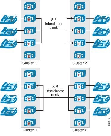
For example, if Cluster 1 (with four active nodes) has a SIP trunk to Cluster 2, and Cluster 2 (with five active nodes) has a SIP trunk to Cluster 1, the following configurations would be needed (see Figure 2-10):
•
–
–
•
–
–
Figure 2-10 SIP Intercluster Trunks Running on All Active Unified CM Nodes
Using Standard Cisco Unified CM Groups and Run on All Active Unified CM Nodes with SIP Intercluster Trunks
In this type of deployment, Run on all Active Unified CM Nodes is used by the SIP intercluster trunk in one cluster and standard Cisco Unified CM Groups are used by the SIP intercluster trunk in the other cluster. When configuring these trunks, the number of remote Cisco Unified CM server destinations that you define should match the number of active Cisco Unified CM nodes associated with the corresponding trunk in the destination cluster. The trunk will automatically load-balance calls across all defined remote destination Cisco Unified CM servers. In the remote cluster, it is important to configure a corresponding SIP intercluster trunk that has Cisco Unified CM nodes with active SIP daemons where these nodes are defined as remote destination Cisco Unified CM servers in the first cluster.
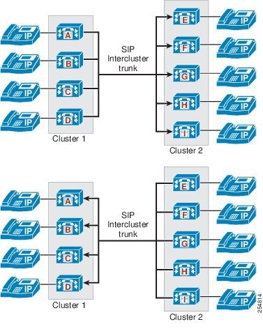
For example, if Cluster 1 has a trunk to Cluster 2, and Cluster 2 has a trunk to Cluster 1, the following configurations would be needed (see Figure 2-11):
•
–
–
•
–
–
Figure 2-11 SIP Intercluster Trunks Using Cisco Unified CM Groups and Run on All Active Unified CM Nodes
Trunk Type and Feature Recommendations for Multi-Cluster Deployments
The following sections provide information about trunk types and feature recommendations for multi-cluster deployments:
•
•
Multiple Clusters All Running Cisco Unified CM 8.5 or Later Releases
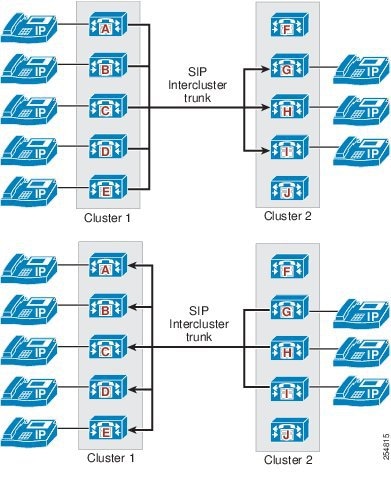
Where all clusters are running Cisco Unified CM 8.5 or later releases, the following SIP trunk features should be used where applicable (see Figure 2-12):
•
•
•
•
•
Deploying these features reduces MTP usage and provides high availability, even call distribution, and dynamic SIP trunk failure detection. For inbound SIP trunk calls to Cisco Unified CM, SIP Early Offer is preferred.
SIP intercluster trunks support voice; video, and encrypted media between Cisco Unified CM clusters, and all of the above features can be used. If multiple trunks are used with route lists, enable the Run on All Active Unified CM Nodes feature on the route lists.
For SIP trunks to an IP PSTN, SIP Early Offer is typically required by the service provider, and most providers support voice calls only. However, if required, video calls and encrypted media are also supported. For inbound SIP trunk calls to Cisco Unified CM, SIP Early Offer is preferred.
SIP trunks to third-party unified communications systems may support voice, video, and encrypted media. Check the capabilities of the end system to determine the SIP trunk features and media capabilities that it supports. For inbound SIP trunk calls to Cisco Unified CM, SIP Early Offer is preferred.
Note
For SIP trunk connections to the IP PSTN and third-party unified communications systems, normalization and transparency scripts can be used to address SIP interoperability issues. Cisco also recommends the deployment of the Cisco Unified Border Element on any IP PSTN SIP trunk connection from Cisco Unified CM to a voice service provider.
Figure 2-12 Multi-Cluster Deployments with Cisco Unified CM 8.5 and Later Releases
Multiple Clusters Running Cisco Unified CM 8.5 and Prior Releases
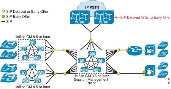
When the leaf clusters are running Cisco Unified CM 8.5 in combination with prior releases of Cisco Unified CM, the following trunk types and features should be used (see Figure 2-13):
When the leaf cluster is running an earlier version (pre-8.5) of Cisco Unified CM and voice, video, and encryption are required, use H.323 Slow Start intercluster trunks and Annex M1 (QSIG) if desired. Deploy one or more H.323 Slow Start intercluster trunks using standard Cisco Unified CM Groups and up to three destination IP addresses. If multiple trunks are used with route lists, to avoid the Route Local rule (described earlier) ensure that the primary server in the route list's Cisco Unified CM Group does not reside on the same node as an associated outbound H.323 trunk.
For leaf clusters running Cisco Unified CM 8.5, use a SIP Delayed Offer intercluster trunk, enable Run on All Active Unified CM Nodes, and use multiple destination IP addresses and SIP OPTIONS Ping for high availability and even call distribution. If multiple trunks are used with route lists, enable the Run on All Active Unified CM Nodes feature on the route lists.
Using SIP Delayed Offer intercluster trunks on Cisco Unified CM 8.5 leaf clusters and H.323 Slow Start intercluster trunks on leaf clusters using earlier versions of Cisco Unified CM, allows voice, video, and encrypted calls to be made between clusters and reduces the number MTPs required. (MTPs are inserted only when required for DTMF translation, transcoding, and so forth.)
For Unified CM Session Management Edition SIP trunks to an IP PSTN, SIP Early Offer is typically required by the service provider, and most providers support voice calls only. Use Early Offer support for Voice and Video (insert MTP if needed) or Delayed Offer on this SIP trunk, and if supported by the end system, SIP OPTIONS Ping, Run on All Nodes, and multiple destination IP addresses. For inbound SIP trunk calls to Cisco Unified CM, SIP Early Offer is preferred.
Unified CM Session Management Edition SIP trunks to third-party unified communications systems may support voice, video, and encrypted media. Use Early Offer support for Voice and Video (insert MTP if needed) or Delayed Offer on this SIP trunk. Check the capabilities of the end system to determine which other Cisco Unified CM SIP trunk features can be used. For inbound SIP trunk calls to Cisco Unified CM, SIP Early Offer is preferred.
Note
For Unified CM Session Management Edition SIP trunk connections to the IP PSTN and third-party unified communications systems, normalization and transparency scripts can be used to address SIP interoperability issues. Cisco also recommends the deployment of the Cisco Unified Border Element on any IP PSTN SIP trunk connection from Cisco Unified CM to a voice service provider.
Figure 2-13 Multi-Cluster Deployments with Cisco Unified CM 8.5 and Prior Releases
Trunk Design Considerations for Clustering over the WAN
When deploying clustering over the WAN for spatial resilience and redundancy, SIP trunk features such as OPTIONS Ping, Early Offer support for Voice and Video (insert MTP if needed), and QSIG can be used as required and appropriate. SIP and H.323 Trunk features such as Run on all Unified CM Nodes and multiple destination addresses should be used with consideration, primarily because of the mechanism that trunks use to identify and accept inbound calls. (A trunk will accept a call if the incoming source IP address matches one of the addresses defined as its destination IP address.)
For clustering over the WAN deployments where calls need to be routed to different groups of Cisco Unified CM nodes based on their geographic location, consideration should be given to the trunk configuration for both inbound and outbound calls. This is described in the following section, using a Unified CM Session Management Edition cluster that is clustered over the WAN as an example.
Design Guidance for Clustering over the WAN with Leaf Cluster Trunks
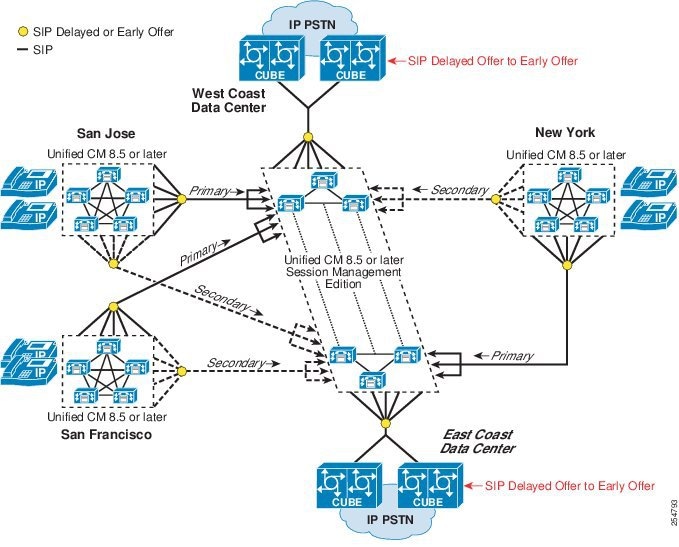
Create and prioritize multiple SIP trunks in route lists in each leaf cluster to distribute calls to each group of Unified CM Session Management Edition nodes in each data center, and run route lists on all nodes. (See Figure 2-14.)
Enable Run on all Nodes on each leaf cluster SIP trunk (each SIP trunk must use a unique incoming port number). Define destination IP addresses per trunk for geographic call distribution.
Figure 2-14 Calls from Leaf Clusters to Cisco Unified CM Session Management Edition
Design Guidance for Clustering over the WAN with Unified CM Session Management Edition Cluster Trunks
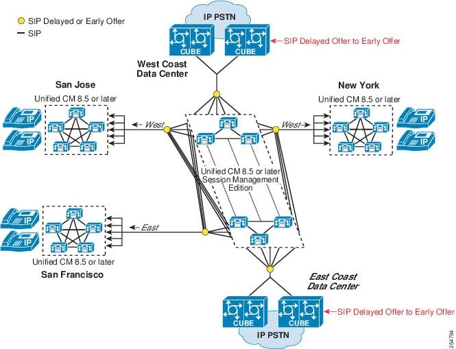
Create and prioritize multiple SIP trunks in route lists in the Unified CM Session Management Edition cluster to initiate calls from each group of Unified CM Session Management Edition nodes in each data center to the leaf cluster. Run route lists on all nodes. (See Figure 2-15.)
Use standard Cisco Unified CM Groups for each SIP trunk, and define destination IP addresses and port numbers for every call processing node in the leaf cluster.
For inbound trunk calls, use local route groups to route outbound calls over trunks in the same data center.
Figure 2-15 Calls from Unified CM Session Management Edition to Leaf Clusters
Other SIP Trunk Deployment Considerations
With Cisco Unified CM, for SIP trunk connections to third-party devices such as SIP-based PBXs or service-provider IP PSTN connections, Cisco recommends the use of the Early Offer support for voice and video calls (insert MTP if needed) feature because this configuration option reduces MTP usage. Alternatively, Delayed Offer for outbound SIP trunk calls can also be used, and this option removes the requirement to assign any MTP resources to the SIP trunk (except in cases where a mismatch in DTMF transport types exists between the called and calling endpoints, in which case Cisco Unified CM will insert an MTP dynamically).
Voice clipping, if observed, can be minimized or eliminated by enabling PRACK on the trunk. This parameter can be enabled in the Service Parameters for the Cisco CallManager Service (SIP Rel1XX Enabled).
Other operating parameters for security settings and the types of messages accepted over a SIP trunk can be enabled in the SIP Trunk Security Profile. Here you can set parameters not only for TLS and Digest Authentication, but also for whether or not the trunk will accept Presence Subscription, an out-of-dialog REFER message, Replaces header, or an Unsolicited Notify message.
SIP trunks support topology-aware RSVP call admission control using SIP Preconditions and locations-based call admission control which is unaware of the underlying WAN topology.
For connection to service provider networks, Cisco recommends the use of the Cisco Unified Border Element. In addition to providing a demarcation point between the enterprise and service provider networks, the Cisco Unified Border Element can also be used for address hiding and enhancing SIP signaling interoperability between the two networks.
For more information on the Cisco Unified Border Element, refer to the documentation available at
http://www.cisco.com/en/US/products/sw/voicesw/ps5640/index.html
H.323 Trunks Overview
H.323 trunks provide connectivity to other H.323 devices such as gateways, Unified CM Session Management Edition, gatekeepers, Unified Communications applications, and other Cisco Unified CM clusters. Cisco Unified CM 8.5 and later releases provide the following call routing enhancement for all H.323 trunk types:
•
In addition to this, H.323 non-gatekeeper controlled intercluster trunks also support the following features:
•
•
These two features improves outbound call distribution from Cisco Unified CM clusters and reduce the number of H.323 non-gatekeeper controlled intercluster trunks required between clusters.
These features and their operation are discussed in detail later in this section.
For the complete list of new enhancements for H.323 trunks, refer to the latest Cisco Unified Communications Manager product release notes available at
http://www.cisco.com/en/US/products/sw/voicesw/ps556/prod_release_notes_list.html
General H.323 Intercluster Trunk Deployment Considerations
Prior to Cisco Unified CM 8.5, H.323 Annex M1 trunks were the preferred choice for connections between Cisco Unified CM clusters. Cisco Unified CM SIP trunks now offer a greater set of features in comparison with H.323 intercluster trunks, thus making SIP the protocol of choice for intercluster trunk connections. However, the majority of Cisco Unified CM clusters using earlier software versions are likely to be deployed with H.323 Annex M1 intercluster trunks, and this may determine the intercluster trunk type that you use to these clusters.
Basic Operation of H.323 Trunks
H.323 trunks provide connectivity to other Cisco Unified CM clusters and other H.323 devices such as gateways. H.323 trunks support most of the audio and video codecs that Cisco Unified CM supports for intra-cluster communications, with the exception of wideband audio and wideband video.
H.323 trunks use the Empty Capabilities Set (ECS) to provide supplementary call services such as hold/resume and transfer. This method is a standard H.245 mechanism to stop or close a media stream (or channel) and start or open it to the same or a different endpoint address. This method allows Cisco Unified CM to keep a call active while still being able to control the source and destination of the media streams on the fly.
For example, consider a call between two clusters (A and B) using the H.323 trunk. When a user in cluster A places a user in cluster B on hold, the media streams between the two users are closed and the user in cluster B is connected to a music on hold (MoH) server in cluster A. The MoH server is instructed to send media (the music file) to the user. When the user in cluster A resumes the call, the MoH stream is closed and the two-way media streams are reopened between the two users. (Cisco Unified CM does not support H.450 for supplementary call services.) In this case, MoH is an example of an ECS operation. H.323 trunks support multicast MoH, therefore the media resource group list (MRGL) for the H.323 trunks can contain both unicast and multicast MoH sources.
The bandwidth used for calls on H.323 trunks can be controlled by the use of regions configured in Cisco Unified CM and assigned to each trunk. A region limits the amount of bandwidth allocated for calls by specifying the inter-region Max Audio Bit Rate for audio and the inter-region Max Video Call Bit Rate setting for video (that includes audio). Calls between one region and another region must be within the specified bandwidth limit. If the device making the call over the H.323 trunk is in a more restrictive region or does not support a particular codec such as video, then it is a subset of codecs that are allowed for that call.
H.323 Trunk Types
The following major types of H.323 trunks can be configured in a Cisco Unified CM:
•
•
•
Each of these H.323 trunk types and their specific design considerations are discussed in the following sections.
Intercluster Trunk (Non-Gatekeeper Controlled)
This trunk is the simplest H.323 trunk type and is used for connecting to other Cisco Unified CM clusters in either a multi-cluster single campus or a distributed call processing deployment. This trunk does not use a gatekeeper for call admission control, although it may use locations configured in Cisco Unified CM if bandwidth control is required.
Cisco Unified CM 8.5 and later releases support the following trunk features and call routing enhancements for H.323 non-gatekeeper controlled intercluster trunks:
•
•
•
These features are discussed in the following sections.
H.323 Non-Gatekeeper Intercluster Trunks Running on all Active Unified CM Nodes
When the Run on all Active Unified CM Nodes option is checked on a H.323 non-gatekeeper intercluster trunk, Cisco Unified CM creates an instance of the H.323 trunk daemon on every call processing Cisco Unified CM Groups.) This allows H.323 non-gatekeeper intercluster trunk calls to be made or received on any call processing subscriber. With Run on all Active Unified CM Nodes enabled, outbound H.323 non-gatekeeper intercluster trunk calls originate from the same server on which the inbound call (for example, from a phone or trunk) is received. As with all Cisco Unified CM H.323 non-gatekeeper intercluster trunks, the H.323 daemons associated with the trunk will accept only inbound calls from end systems with IP addresses that are defined in the trunk's destination address fields. Running the H.323 non-gatekeeper intercluster trunk on all nodes is recommended where the H.323 a non-gatekeeper intercluster trunk is required to process a large number of calls, so that outbound and inbound call distribution can be evenly spread across all call processing subscribers within a cluster. Bear in mind that (unlike SIP trunks) H.323 non-gatekeeper intercluster trunks use a fixed destination port and an ephemeral source, and therefore H. 323 non-gatekeeper intercluster trunks cannot be differentiated using port numbers. When configuring H.323 non-gatekeeper intercluster trunks, make sure that each trunk uses different destination IP addresses when Run on all Active Unified CM Nodes is enabled.
Up to 16 Destination IP Addresses per H.323 Non-Gatekeeper Intercluster Trunk
An H.323 non-gatekeeper intercluster trunk can be configured with up to 16 destination IP addresses. Support for additional destination IP addresses reduces the need to create multiple trunks associated with route lists and route groups for call distribution between two Unified Communications systems, thus simplifying Cisco Unified CM trunk design. This feature can be used in conjunction with the Run on all Active Unified CM Nodes feature. Bear in mind, however, that the H.323 daemons associated with a Cisco Unified CM H.323 non-gatekeeper intercluster trunk will accept only inbound calls from end systems with IP addresses that are defined in the trunk's destination address fields.
Route Lists Running on All Active Unified CM Nodes
Although this is not specifically an H.323 non-gatekeeper intercluster trunk feature, running route lists on all nodes provides benefits for trunks in route lists and route groups. Running route lists on all nodes improves outbound call distribution by using the Route Local rule to avoid unnecessary intra-cluster traffic.
For route lists, the Route Local rule operates as follows:
For outbound calls that use route lists and associated route groups and trunks, when a call from a registered phone or inbound trunk arrives at the node with the route list instance associated with the trunk selected for the outbound call, Cisco Unified CM checks to see if an instance of the selected outbound trunk exists on the same node as the route list. If so, Cisco Unified CM will use this node to establish the outbound trunk call.
If both the route list and the selected outbound trunk have Run on all Active Unified CM Nodes enabled, outbound call distribution will be determined by the node on which the inbound call arrives. When the selected outbound trunk uses Unified Groups instead of running on all nodes, Cisco Unified CM will apply the Route Local rule if an instance of the selected outbound trunk exists on the same node on which the inbound call arrived. If an instance of the trunk does not exist on this node, then Cisco Unified CM will forward the call (within the cluster) to a node where the trunk is active.
If the route list does not have Run on all Active Unified CM Nodes enabled, the route list will be active on one node within the cluster (the primary node in the route list's Unified Group) and the Route Local rule will be applied on this node.
As a general recommendation, Run on all Active Unified CM Nodes should be enabled for all route lists.
Design Considerations for H.323 Non-Gatekeeper Intercluster Trunks
For intercluster trunk connections, the H.323 non-gatekeeper intercluster trunk configured in each cluster may be using standard Cisco Unified CM Groups or the Run on all Active Unified CM Nodes feature. The reasons for using each type of feature will typically be determined by the Cisco Unified CM version used by a cluster, or if clustering over the WAN has been deployed and geographically based call distribution is required.
Using Standard Cisco Unified CM Groups with H.323 Non-Gatekeeper Intercluster Trunks
In this type of deployment, standard Cisco Unified CM Groups are used by H.323 non-gatekeeper intercluster trunks in each cluster. When defining this type of trunk with standard Cisco Unified CM Groups, you should define a maximum of three remote Cisco Unified CM servers in the destination cluster. The trunk will automatically load-balance calls across all servers defined as remote destination addresses. In the remote cluster, it is important to configure a corresponding intercluster trunk (non-gatekeeper controlled) that has the same Cisco Unified CM nodes in its Cisco Unified CM Group as those defined as remote destination Cisco Unified CM servers in the first cluster.
For example, if Cluster 1 has a trunk to Cluster 2, and Cluster 2 has a trunk to Cluster 1, the following configurations would be needed (see Figure 2-16):
•
–
–
•
–
–
Figure 2-16 H.323 Non-Gatekeeper Intercluster Trunks Using Standard Cisco Unified CM Groups
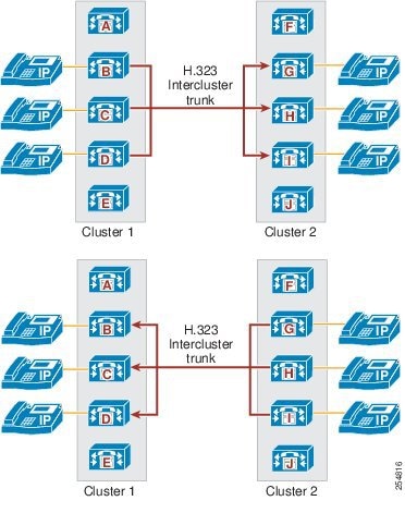
Using Run on All Active Unified Nodes with H.323 Non-Gatekeeper Intercluster Trunks
In this type of deployment, Run on all Active Unified CM Nodes is used by the H.323 non-gatekeeper intercluster trunks in each cluster. When defining this type of trunk, you may define up to 16 remote Cisco Unified CM servers in the destination cluster. (The number of remote servers that you need will depend on the number of active Cisco Unified CM nodes in the destination cluster.) The trunk will automatically load-balance calls across all defined remote destination Cisco Unified CM servers. In the remote cluster, it is important to configure a corresponding intercluster trunk (non-gatekeeper controlled) that has Run on all Active Unified CM Nodes configured, where these nodes are defined as the remote destination Cisco Unified CM servers in the first cluster.
For example, if Cluster 1 (four nodes) has a trunk to Cluster 2, and Cluster 2 (five nodes) has a trunk to Cluster 1, the following configurations would be needed (see Figure 2-17):
•
–
–
•
–
–
Figure 2-17 H.323 Non-Gatekeeper Intercluster Trunks Using Run on All Active Unified Nodes
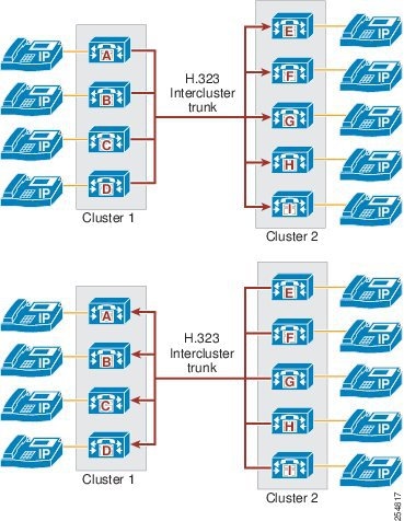
Using Standard Cisco Unified CM Groups and Run on All Active Unified CM Nodes with H.323 Non-Gatekeeper Intercluster Trunks
In this type of deployment, Run on all Active Unified CM Nodes is used by the H.323 non-gatekeeper intercluster trunk in one cluster, and standard Cisco Unified CM Groups are used by the H.323 non-gatekeeper intercluster trunk in the other cluster. When configuring these trunks, the number of remote Cisco Unified CM server destinations that you define should match the number of active Cisco Unified CM nodes for the corresponding trunk in the destination cluster. The trunk will automatically load-balance calls across all defined remote destination Cisco Unified CM servers. In the remote cluster, it is important to configure a corresponding intercluster trunk (non-gatekeeper controlled) that has Cisco Unified CM nodes with active H.323 daemons where these nodes are defined as remote destination Cisco Unified CM servers in the first cluster.
For example, if Cluster 1 has a trunk to Cluster 2, and Cluster 2 has a trunk to Cluster 1, the following configurations would be needed (see Figure 2-18):
•
–
–
•
–
–
Figure 2-18 H.323 Non-Gatekeeper Intercluster Trunks Using Standard Cisco Unified CM Groups and Run on All Active Unified CM Nodes
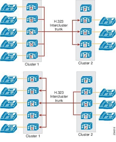
High Availability for Non-Gatekeeper Controlled Intercluster Trunks
High availability and redundancy for H.323 non-gatekeeper intercluster trunks can be provided by using multiple source Cisco Unified CM servers for originating calls and multiple destination IP addresses per trunk.
Multiple Source Cisco Unified CM Servers for Originating H.323 Non-Gatekeeper Intercluster Trunk Calls
•
The nodes defined in the Cisco Unified CM Group associated with an individual trunk make up the set of servers that can place or receive calls over that trunk. Up to three nodes can be defined in a Cisco Unified CM Group, thus ensuring high availability of the trunk itself.
•
The Run on all Active Unified CM Nodes feature creates and enables an H.323 trunk instance on each call processing subscriber within the cluster, thus allowing these nodes to place or receive calls over that trunk.
•
The Route Local feature in Cisco Unified CM is designed to reduce intra-cluster traffic. The feature operates as follows: When a device such as a phone is making an outbound call over H.323 intercluster trunk ICT 1, if an instance of H.323 ICT 1 is active on the same node as the one to which the phone is registered, then always use this co-located H.323 ICT 1 instance rather than internally route the call to another H.323 ICT 1 instance on another node within the cluster.
The effect of the Route Local feature on node selection depends on whether Cisco Unified CM Groups or Run on all Active Unified CM Nodes is configured on the trunk. For trunks with Run on all Active Unified CM Nodes configured, the node to which the calling device is registered is used to make the outbound H.323 intercluster trunk call. When Cisco Unified CM Groups are used on the trunk, if the calling device is registered to one of the nodes in the trunk's Cisco Unified CM Group, then the Route Local rule applies. If the calling device is not registered to one of the nodes in the trunk's Cisco Unified CM Group, then Cisco Unified CM will randomly distribute the call over the nodes in the trunk's Cisco Unified CM Group.
In general, using Run on all Active Unified CM Nodes is recommended for H.323 intercluster trunks because call distribution across nodes is determined by the calling device and intra-cluster traffic is minimized.
Multiple Destination IP Addresses per H.323 Non-Gatekeeper Intercluster Trunks
A single H.323 non-gatekeeper intercluster trunk can be configured with up to 16 destination IP addresses. Cisco Unified CM uses round-robin distribution to the configured destination IP addresses when placing calls over an H.323 non-gatekeeper intercluster trunk.
Design Considerations When Using Run on All Active Unified CM Nodes
When using Run on All Active Unified CM Nodes in conjunction with multiple destination addresses, be aware that to accept inbound calls, the inbound source IP address received on the H.323 trunk must match with a configured destination IP address on the inbound trunk. Where clustering over the WAN designs are deployed and geographic call distribution and failover are required, use standard Cisco Unified CM Groups on multiple intercluster trunks (each with up to three destination IP addresses) in conjunction with route lists and route groups.
Load Balancing for H.323 Non-Gatekeeper Intercluster Trunks
When designing load balancing for H.323 non-gatekeeper intercluster trunks, consider both the node that sources the call and its destination. With H.323 non-gatekeeper intercluster trunks, the node that originates the call is determined by the Route Local rule, the number of nodes on which the outbound trunk is active, and whether a route list is used in conjunction with multiple outbound trunks. These considerations are discussed below.
Outbound Calls over a Single H.323 Non-Gatekeeper Intercluster Trunk
A single H.323 non-gatekeeper intercluster trunk can run on up to three Cisco Unified CM nodes in a Cisco Unified CM Group or on all active Cisco Unified CM nodes in the cluster. To select the source node for outbound calls, Cisco Unified CM applies the following decision processes:
Where an instance of the trunk runs on all nodes, the Route Local rule applies and the node used for each outbound call is determined by the node on which the call arrives (for example, the node to which the calling phone is registered or the node on which the inbound trunk call arrives). Where Cisco Unified CM Groups are used, the route local rule still applies for those calling devices that are registered to the same node as the nodes in the trunk's Cisco Unified CM Group. For calling devices that are registered to other servers within the cluster, Cisco Unified CM will randomly distribute calls across the nodes in the trunk's Cisco Unified CM Group. Cisco Unified CM uses round-robin call distribution across the trunk's configured destination addresses. H.323 non-gatekeeper intercluster trunks may be configured with up to 16 destination IP addresses.
Outbound Calls over Multiple H.323 Non-Gatekeeper Intercluster Trunks
Because H.323 non-gatekeeper intercluster trunks can run on all active Cisco Unified CM nodes and have up to 16 destination addresses, you typically do not have to use multiple H.323 non-gatekeeper intercluster trunks to provide even call distribution between two Unified Communications clusters. Where multiple trunks are used with route lists and route groups, route lists should be enabled to run on all active Cisco Unified CM nodes. Multiple H.323 trunks are often used in conjunction with route lists to provide failover to the PSTN or to a group of Cisco Unified CM servers in a different site as part of a clustering over the WAN deployment. The selection of the Cisco Unified CM node used to initiate an outbound trunk call and the distribution of calls over the trunk's configured destination IP addresses is determined in the same way as described for single trunks. Where clustering over the WAN designs are deployed and geographic call distribution and failover are required, use multiple intercluster trunks (each with up to three destination IP addresses) with standard Cisco Unified CM Groups in conjunction with route lists and route groups.
Intercluster Trunk (Gatekeeper Controlled)
The intercluster gatekeeper controlled trunk can be used instead of the non-gatekeeper controlled trunk to interconnect a large number of Cisco Unified CM clusters. The advantages of using the gatekeeper controlled trunk are mainly the overall administration of the cluster and failover times. With non-gatekeeper controlled trunks, if a subscriber server in a cluster becomes unreachable, there will be a 5-second (default) timeout while the call is attempted. If an entire cluster is unreachable, the number of attempts before either call failure or rerouting over the PSTN will depend on the number of remote servers defined for the trunk and on the number of trunks in the route list or route group (if any). If there are many remote servers and many non-gatekeeper controlled trunks, the call delay can become excessive.
With a H.323 gatekeeper controlled trunk, you configure only one trunk that can then communicate by means of the gatekeeper with all other clusters registered to the gatekeeper. If a cluster or subscriber becomes unreachable, the gatekeeper automatically directs the call to another subscriber in the cluster or rejects the call if no other possibilities exist, thus allowing the call to be rerouted over the PSTN (if required) with little incurred delay. With a single Cisco gatekeeper, it is possible to have 100 clusters all registering a single trunk each, with all clusters being able to call each other. The gatekeeper controlled intercluster trunk should be used for communicating only with other Cisco Unified CMs because the use of this trunk with other H.323 devices might cause problems with supplementary services.
Note
H.225 Trunk (Gatekeeper Controlled)
The H.225 gatekeeper controlled trunk is essentially the same as the intercluster gatekeeper controlled trunk except that it has the capability of working with Cisco Unified CM clusters as well as other H.323 devices such as gateways, conferencing systems, and clients. This capability is achieved through a discovery mechanism on a call-by-call basis. (See H.323 Operation in Cisco Unified CM, for details of this discovery process.)
Note
High Availability for Gatekeeper Controlled Trunks
Redundancy can be achieved in several ways, depending on the requirements of the design. The simplest method is to configure a gatekeeper controlled trunk and assign up to three subscribers in the Cisco Unified CM Group associated with the device pool assigned to that trunk. This configuration will cause all servers to register with the same gatekeeper in the same zone with the same technology prefix. However, the H.323 trunk name that is used for the h323_id will have a suffix of "_n" where n is the node number in the cluster. This ID is automatically generated and cannot be changed. You configure a single trunk, but the gatekeeper registers multiple trunks, one from each subscriber in the Cisco Unified CM Group.
If you have additional redundancy requirements, it is possible to configure another gatekeeper controlled trunk with a different name and different subscribers in the Cisco Unified CM Group, but with all the other parameters identical to the first trunk. This second trunk will cause additional subscribers to register with the gatekeeper.
Cisco recommends assigning device pools that contain a Cisco Unified CM Group consisting of the two servers that make up the standard subscriber pair. (See Call Processing Subscriber Redundancy, page 8-16, for more information on subscriber redundancy.) For complete redundancy in each full cluster, four trunks would be needed, using four different device pools and resulting in eight subscribers registering with the gatekeeper. (The same result could be achieved with three trunks and larger Cisco Unified CM Groups.)
During registration, several parameters are passed between Cisco Unified CM and the gatekeeper. Cisco Unified CM uses an ephemeral User Datagram Protocol (UDP) port for gatekeeper Registration Admission Status (RAS) messages. This port would normally be UDP 1719. However, Cisco Unified CM must be able to identify precisely which H.323 daemon is the originator of a RAS message from a particular server; therefore it uses a range of UDP ports and assigns them dynamically.
During the registration process, a trunk registers the following information for the other subscribers in its Cisco Unified CM Group:
•
•
•
•
•
If the recommended clustered gatekeepers are used, the gatekeeper will return a list of alternate gatekeeper addresses that may be used if the primary gatekeeper fails or does not have sufficient available resources.
Figure 2-19 shows a cluster of gatekeepers that use Gatekeeper Update Protocol (GUP) to communicate. (See the chapter on Call Processing, page 8-1, for more information on gatekeepers.)
Figure 2-19 Gatekeeper Cluster
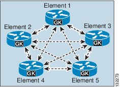
If an H.323 trunk has only a single subscriber in its Cisco Unified CM Group, there will be only one connection between the configured gatekeeper in Cisco Unified CM and the gatekeeper cluster, as illustrated in Figure 2-20.
Figure 2-20 H.323 Trunk with a Single Cisco Unified CM Subscriber
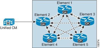
If there are multiple subscribers in the Cisco Unified CM Group associated with the trunk, additional connections will be established between the Cisco Unified CM cluster and the gatekeeper cluster, as illustrated in Figure 2-21.
Figure 2-21 H.323 Trunk with Multiple Cisco Unified CM Subscribers
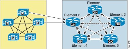
This approach provides redundancy for subscriber failures as well as gatekeeper failures after registration because the alternate gatekeeper is communicated when the trunk registers. This approach does not, however, provide redundancy if the configured gatekeeper is unavailable at initial registration or following a reset because the list of alternate gatekeepers is dynamic and not stored in the database. To provide an additional level of redundancy as well as load balancing, an additional gatekeeper from the gatekeeper cluster is configured in Cisco Unified CM. For example, if the original trunk is registered with Element 2, the additional gatekeeper could be configured as Element 4, as illustrated in Figure 2-22.
Figure 2-22 Additional Gatekeeper Configured for Load Balancing and Additional Redundancy
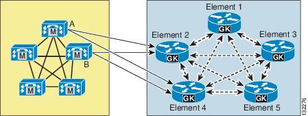
The Cisco Unified CM configuration for the example in Figure 2-22 would contain the following components:
•
•
Using this approach, the Cisco Unified CM cluster will still be able to register when either Element 2 or Element 4 is not reachable during initial registration (that is, during power-up or trunk reset).
Load balancing of calls inbound to the Cisco Unified CM cluster is done automatic by default because the gatekeeper randomly selects one of the subscribers registered within the zone. If this is not the desired behavior, you can use the gw-priority configuration command in the gatekeeper to modify this default behavior, as illustrated in Example 2-3.
Example 2-3 Using the gw-priority Command to Direct Calls to a Particular Trunk
gatekeeperzone local SJC cisco.com 10.0.1.10zone prefix SJC 1408....... gw-priority 10 sjc-trunk_2zone prefix SJC 1408....... gw-priority 9 sjc-trunk_3zone prefix SJC 1408....... gw-default-priority 0gw-type-prefix 1#* default-technologyarq reject-unknown-prefixno shutdownendpoint ttl 60In Example 2-3, the H.323 trunk was configured as sjc-trunk in Cisco Unified CM, and the "_2" and "_3" suffixes are appended automatically by the Cisco Unified CM subscribers to indicate which node number they are in the cluster. Therefore, this example uses node 2 as the first choice, which should be the highest-priority Cisco Unified CM in the Cisco Unified CM Group for this trunk. Node 3 is the second choice in this case.
The use of gw-default-priority 0 is optional. It was used in this example to disable the use of any other trunk that might accidentally be configured to register in this zone.
Load Balancing Outbound Calls over H.323 Gatekeeper Controlled Trunks
With Cisco Unified CM H.323 gatekeeper controlled trunks, the node from which the call originates is determined by the Route Local rule, the number of nodes on which the outbound trunk is active, and whether a route list is used in conjunction with multiple outbound trunks. These considerations are discussed below.
Outbound Call Load Balancing When Deploying a Single H.323 Gatekeeper Controlled Trunk
For the initiation of outbound calls over a single H.323 gatekeeper controlled trunk, the route local rule applies and the following factors within a Cisco Unified CM cluster determine which server is selected:
•
•
For a single H.323 gatekeeper controlled trunk, the Route Local process of server selection for outgoing calls operates as follows:
•
•
Outbound Call Load Balancing When Deploying Route Lists in Conjunction with H.323 Gatekeeper Controlled Trunks
In configurations where route lists are employed to select a trunk for outbound calls, enable Run on all Active Unified CM Nodes for all route lists. Running route lists on all nodes improves outbound call distribution by using the Route Local rule to avoid unnecessary intra-cluster traffic. For route lists, the Route Local rule operates as follows:
For outbound calls that use route lists (and associated route groups and trunks), when a call (from a registered phone or inbound trunk) arrives at the node with the route list instance associated with the outbound trunk call, Cisco Unified CM checks to see if an instance of the selected outbound trunk call exists on the same node as the route list. If so, Cisco Unified CM will use this node to establish the outbound trunk call.
If the route list has Run on all Active Unified CM Nodes enabled: For gatekeeper controlled trunks using Cisco Unified CM Groups, Cisco Unified CM will apply the route local rule if an instance of the selected outbound trunk exists on the same node on which the inbound call arrived. If an instance of the trunk does not exist on this node, then Cisco Unified CM will forward the call (within the cluster) to a node where the trunk is active.
If the route list does not have Run on all Active Unified CM Nodes enabled, the route list will be active on one node within the cluster (the primary node in the route list's Cisco Unified CM Group) and the Route Local rule will be applied on this node.
H.323 Outbound FastStart Call Connections
Calls that are placed from IP phones over large WAN topologies with long delays can experience voice clipping when the called party goes off-hook to answer the call. When H.323 trunks or gateways are separated from the Cisco Unified CM server, significant delays can occur because of the many H.245 messages that are exchanged when a call is set up.
With the FastStart feature, information that is required to complete a media connection between two parties gets exchanged during the H.225 portion of call setup, and this exchange eliminates the need for H.245 messages. The connection experiences one round-trip WAN delay during call setup, and the calling party does not experience voice clipping when the called party answers the call.
Cisco Unified CM uses media termination points (MTPs) for making an H.323 outbound FastStart call. Cisco Unified CM starts an outbound FastStart call by allocating an MTP and opening the receive channel. Next, the H.323 Fast Connect procedure sends the SETUP message with a FastStart element to the called endpoint. The FastStart element includes information about the receiving channel for the MTP.
By default, H.323 FastStart is disabled. To enable H.323 FastStart, check the MTP Required and Enable Outbound FastStart checkboxes on the H.323 trunk, and select the desired Codec For Outbound FastStart. Also note that Inbound FastStart is enabled separately with check box Enable Inbound FastStart. (Inbound FastStart does not require an MTP or a codec selection.)
Note
H.323 Trunks with Media Termination Points
Media termination points (MTPs) are generally not required for normal operation of the H.323 trunk. They are, however, required for communication with devices that are H.323 Version 1, that do not support the Empty Capabilities Set (ECS) for supplementary services, or that require H.323 FastStart.
To test whether or not an MTP is required, use the following simple procedure:
1.
2.
DTMF Transport
The H.323 trunk supports DTMF signaling for both out-of-band DTMF using H.245 and in-band DTMF using RTP Named Telephone Events (RFC 2833). There are no configuration options. An MTP may be allocated dynamically to convert between out-of-band DTMF relay to in-band DTMF relay, if required.
H.323 Trunk Transport Protocols
H.323 trunks use TCP for H.225 call control and H.245 media control signaling, and UDP for gatekeeper H.225 Registration Admission Status (RAS) signaling.
Secure H.323 Trunks
Securing H.323 trunks involves two processes: configuring the trunk to encrypt media and configuring the trunk to encrypt signaling.
Media Encryption
Media encryption can be configured on H.323 trunks by checking the trunk's SRTP allowed check box. It is important to understand that checking the SRTP allowed checkbox will cause the media for calls to be encrypted but the trunk signaling will not be encrypted, therefore the session keys used to establish the secure media stream will be sent in the clear. It is therefore important to ensure that signaling between Cisco Unified CM and its destination H.323 trunk device is also encrypted so that keys and other security-related information do not get exposed during call negotiations.
Signaling Encryption
H.323 trunks use IPSec for signaling encryption. You may configure IPSec in the network infrastructure, or you may configure IPSec between Cisco Unified Communications Manager (Cisco Unified CM) and the remote gateway or trunk. If you implement one method to set up IPSec, you do not need to implement the other method. Using IPSec on Cisco Unified CM servers can incur a significant impact on server performance, therefore Cisco recommends that you provision IPSec in the network infrastructure rather than in Cisco Unified CM itself.
If the system can establish a secure media or signaling path and if the end devices support SRTP, the system uses an SRTP connection. If the system cannot establish a secure media or signaling path or if at least one device does not support SRTP, the system uses an RTP connection. SRTP-to-RTP fallback (and vice versa) may occur for transfers from a secure device to a non-secure device, conferencing, transcoding, music on hold, and so on.
For SRTP-configured devices, Cisco Unified CM classifies a call as encrypted if the SRTP Allowed check box is checked for the device and if the SRTP capabilities for the devices are successfully negotiated for the call. If the preceding criteria are not met, Cisco Unified CM classifies the call as non-secure. If the device is connected to a phone that can display security icons, the phone displays the lock icon when the call is encrypted.
MTPs that are statically assigned to an H.323 trunk using the MTP Required checkbox do not support SRTP because they do not support the pass-through codec. To ensure that SRTP is supported for all calls, do not configure the H.323 trunk for H.323 Outbound FastStart (that is, do not select MTP Required). SRTP is supported for Inbound FastStart. (Inbound FastStart does not require an MTP or a codec selection.)
H.323 Operation in Cisco Unified CM
This section provides information on how the H.323 protocol is used and implemented in Cisco Unified CM, and it explains how and why certain features work the way they do.
The most important point to understand is which subscribers run the call signaling daemons. These daemons are pieces of code that make and receive H.323 calls. They are usually referred to as H.323 or H.225 daemons (H.323Ds or H.225Ds). H.225 is part of the H.323 protocol and is mainly responsible for call control. H.245 is the other major component of H.323 that is responsible for the media control of a call.
For the majority of H.323 devices, the subscribers listed in the Cisco Unified CM Group for a particular H.323 device determine which subscribers run the daemons and when. For H.323 non-gatekeeper controlled intercluster trunks, standard Cisco Unified CM Groups can be used or the Run on All Active Unified CM Nodes can be enabled, in which case the daemon will run on all active nodes.
For devices using Cisco Unified CM Groups, it is important to know which nodes will run H.225 daemons because calls sent to an incorrect subscriber might be rejected. For example, this situation would occur if a Cisco IOS H.323 gateway is configured with dial peers that send calls to subscriber C in a Cisco Unified CM cluster but the Cisco Unified CM Group for that gateway has only subscribers A and B in its list. In such a case, the call will fail or be handled by an H.323 trunk daemon if one happens to be configured on the subscriber.
The following scenarios describe where and when H.225Ds are created on subscribers:
•
The H.225D is active on only the highest-priority subscriber available in the Cisco Unified CM Group associated with the H.323 client.
If the H.323 client is gatekeeper controlled, the RasAggregator device registers from only the highest-priority subscriber available in the Cisco Unified CM Group associated with the gatekeeper controlled H.323 client.
The RasAggregator is a special device that registers in gatekeeper zones for the purpose of providing two specific features:
–
–
•
The H.225D is active on all subscribers in the Cisco Unified CM Group associated with the H.323 gateway.
•
The H.225D is active on all subscribers in the Cisco Unified CM Group associated with the H.323 trunk. A RAS daemon registers the trunk with the gatekeeper from all subscribers in the associated Cisco Unified CM Group.
•
The H.225D is active on all subscribers in the Cisco Unified CM Group associated with the H.323 trunk.
•
The H.225D is active on all active Cisco Unified CM subscribers in the cluster.
When an incoming H.323 call is made to a subscriber in a Cisco Unified CM cluster, various decisions are made to determine if the call is accepted or rejected and which H.225D will receive the call if it is accepted. Figure 2-23 shows how this process works.
Figure 2-23 Process for Determining if an H.323 Call is Accepted or Rejected
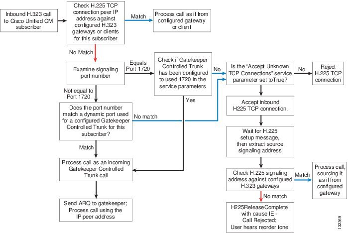
Cisco Unified CM H.323 protocol includes the following additional features:
•
This feature provides the ability to determine, on a call-by-call basis, if the calling device is from Cisco Unified CM. Whenever a call is received, Cisco Unified CM looks for an H.225 User-to-User Information Element (UUIE) that indicates if the other end is another Cisco Unified CM. If it is, it will always use the Intercluster Trunk Protocol. If no UUIE is found, it will use the configured protocol for that device. This feature enables an H.225 gatekeeper controlled trunk to switch between Intercluster Trunk Protocol and H.225 on a call-by-call basis, allowing a mixture of Cisco Unified CM clusters and other H.323 devices to use the gatekeeper. Intercluster Trunk Protocol is the same as H.225 except for several differences that enable specific features to work correctly between Cisco Unified CM clusters.
•
This feature can be enabled on all H.323 trunks. It allows specific H.323 Annex M1 features to be implemented between Cisco Unified CM clusters and other verified systems that also support H.323 Annex M1. These features include:
–
–
–
•
When registering with a gatekeeper that supports this feature, such as a Cisco Multimedia Conference Manager (MCM) Gatekeeper, Cisco Unified CM can inform the gatekeeper of alternate destinations for calls to the H.323 trunk. These alternate endpoints or destinations are sent to the calling device by the gatekeeper when this H.323 trunk is called. They are the other subscribers listed in the Cisco Unified CM Group associated with the H.323 trunk that registers with the gatekeeper.
•
When an H.323 trunk registers with a gatekeeper that supports this feature (for example, a Cisco gatekeeper cluster), Cisco Unified CM is dynamically informed about other gatekeepers that can process registrations, call admission requests, and other RAS functions in the event that this gatekeeper fails or exhausts its own resources.
•
When an H.323 trunk sends an admission request (ARQ) to the gatekeeper, it might receive a different E.164 number in the admission confirmation message (ACF), indicating that the original called number should be replaced with this new one. This feature requires a route server using Gatekeeper Transaction Message Protocol (GKTMP) to communicate with Cisco gatekeepers.
Note
•
H.323 trunks can update the gatekeeper with bandwidth information to indicate a change in the requested bandwidth allocated to a specific call. This feature is disabled by default and is controlled by setting the Cisco Unified CM service parameter BRQ Enabled to True, under the H.323 section. This feature is especially important when video is used on an H.323 trunk because the original bandwidth request is for the maximum amount allowed. Enabling this feature ensures that call admission control uses the actual bandwidth negotiated during call setup.
Other Design Considerations for H.323 Trunks
Cisco Unified CM SIP trunks now offer a greater set of features in comparison with H.323 intercluster trunk, making SIP the protocol of choice for intercluster trunk connections, although H.323 Annex M1 may still be preferred for intercluster trunk connections to Cisco Unified CM clusters using earlier software versions. For more information on deploying intercluster trunks in multi-cluster and clustering over the WAN environments, see Design Considerations for SIP Trunks.
General SIP and H.323 Trunk Design Considerations
The following sections describe SIP and H.323 trunk considerations:
•
•
Deterministic Outbound Call Load Balancing over Cisco Unified CM Trunks
In the majority of cases, using Run on all Active Unified CM Nodes or assigning Cisco Unified CM Groups to devices is sufficient to handle the call distribution of outbound calls over trunks from call processing subscribers. Due to the Route Local rule, trunk calls might appear to originate randomly from call processing subscribers, but the trade-off for this random call origination is reduced call processing and reduced Intra-Cluster Communication Signaling (ICCS) traffic within the cluster.
Deterministic load balancing of outbound IP trunk calls across call processing servers is possible but can be counter-productive because the advantages gained from predictable call origination within the cluster can be outweighed by the increase in ICCS traffic created by calls from phones registered to one subscriber extending their communication to another server within the cluster to originate the outgoing IP trunk call.
Predictable and deterministic subscriber-based load balancing of outgoing IP trunk calls can be achieved as follows:
•
For example, to spread outbound trunk calls across four subscribers in the cluster, perform the following tasks:
–
–
Group A: Subscriber A
Group B: Subscriber B
Group C: Subscriber C
Group D: Subscriber D
With no backup subscribers defined, if the primary subscriber for the specified trunk fails, Cisco Unified CM will re-route outgoing calls to the next trunk in the route group.
•
–
–
Group A: Subscriber A
Group B: Subscriber B
Group C: Subscriber C
Group D: Subscriber D
Group E: Subscriber E
Group F: Subscriber F
Group G: Subscriber G
Group H: Subscriber H
Codec Selection Over IP Trunks
Before media between communicating entities can be established, both the entities must agree on the codec(s) that they want to use. This codec (or codecs if both audio and video are involved) is derived from the intersection of codecs supported by communicating entities involved and the configured policy in Cisco Unified CM. Policy in Cisco Unified CM is configured by region settings. The inter-region Max Audio Bit Rate for audio and the inter-region Max Video Call Bit Rate setting for video (that includes audio) determine the set of codecs that will be used between devices contained in the respective regions. Note that the bit rate settings determine only the maximum bandwidth that is allowed for devices communicating across those regions and does not specify the exact codec that will be used for every call. If the entities share several codecs in common and the inter-region bit rate setting allows the selection of more than one codec, Cisco Unified CM will select the codec with the best quality without consideration of the actual bit rate of the codec.
For example, if the inter-region audio bit rate setting between a trunk and an IP phone is set to 8 kbps (G.729) and both endpoints indicate support for G.729, then that codec will be selected. However, if the inter-region audio bit rate is set to 64 kbps (G.722 and G.711) and both endpoints indicate support for G.711, G.722, and G.729, then Cisco Unified CM will choose G.722 because this codec will deliver the best audio quality. The codec selection rules change somewhat when the Link Loss Type for the region is characterized as being Lossy. In this case the iSAC codec, if supported by the communicating sides and allowed by the inter-region bit rate setting, takes priority over others because it can deliver good audio quality at a lower bit rate.
For calls over SIP and H.323 trunks, the codec selected for use for calls over a trunk is determined by the capabilities of the remote endpoint as learned from the call setup messages, capabilities of the local endpoint, and the inter-region bit rate settings between the trunk and the local endpoint regions.
Note
Note
Other MTP Uses
MTPs are very useful for terminating media streams from other devices that make calls over trunks and for re-originating the media streams with the same voice payload; however, in such cases the IP address is changed to that of the MTP. With this fact in mind, you can utilize MTPs in the following scenarios:
•
•
With both of these methods, if the MTP Required box is checked, the default behavior is to allow calls on SIP and H.323 trunks even if MTP resources are unavailable or exhausted. This default behavior might result in no voice path for the call, but the behavior can be changed by setting the Cisco Unified CM service parameter Fail Call if MTP allocation fails under the SIP and H.323 sections to True.
Other Design Considerations for Unified CM Session Management Edition Deployments
The following topics describe design considerations and guidelines that apply to deployments of Unified CM Session Management Edition:
•
•
•
•
•
•
•
•
Unified CM Session Management Edition and SAF CCD Deployments
Unified CM Session Management Edition deployments provide internal dial plan aggregation. Cisco Service Advertisement Framework (SAF) Call Control Discovery (CCD) deployments distribute both the internal dial plan and the corresponding external "To PSTN" dial plan to participating SAF CCD Unified Communications systems. Combining Unified CM Session Management Edition and SAF CCD enables Unified CM Session Management Edition to act as the central session manager for all leaf Unified Communications systems, while also using SAF CCD to distribute both the internal and external "To PSTN" dial plans to all SAF CCD participating Cisco Unified CM leaf clusters.
A Unified CM Session Management Edition and SAF hybrid deployment uses a specific configuration of SAF CCD to allow all calls between leaf clusters to be routed only through the Unified CM Session Management Edition cluster. The SAF configuration consists of two parts:
•
•
Note
Advertising SAF CCD Routes to Leaf Clusters from/through Unified CM Session Management Edition
On the Unified CM Session Management Edition cluster, create the DN patterns, DN Groups, and corresponding "to DID" rules for the internal number ranges and external "To PSTN" numbers hosted by each SAF-enabled leaf cluster. Publish these DN patterns to the SAF AS by associating them with one or more SAF-enabled trunks and advertising services. These DN patterns and corresponding routes to Unified CM Session Management Edition are learned by all SAF-enabled leaf clusters. While Unified CM Session Management Edition is reachable through the IP WAN, all intercluster calls are routed through Unified CM Session Management Edition. When Unified CM Session Management Edition is unreachable, intercluster calls are routed through the leaf cluster's local PSTN gateway after the called number has been modified using the learned DN pattern's "to DID" rule.
Advertising SAF CCD Routes from Leaf Clusters to Unified CM Session Management Edition
The purpose of advertising each leaf cluster's hosted DN ranges to the SAF AS is to allow the Unified CM Session Management Edition cluster to learn about these DN ranges and leaf cluster reachability. These number ranges are also learned by all other leaf clusters. (See Figure 2-24.) To prevent direct leaf-to-leaf routes from being used, in each leaf cluster, block learned routes from all other leaf clusters. Routes can be blocked based on whether they match either the IP address the SAF nodes in each of the leaf clusters or (preferably) the Remote Call Control Entity Name for each leaf cluster. (This is the Cisco Unified CM Cluster ID in the Cisco Unified CM Enterprise Parameters menu.)
Figure 2-24 Advertising SAF CCD Routes in a Unified CM Session Management Edition Deployment
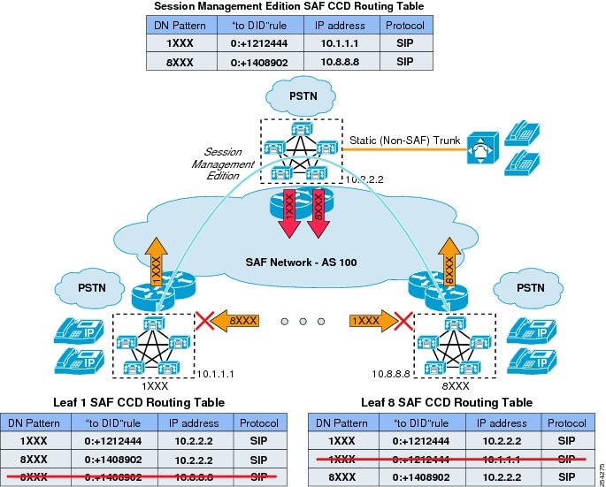
Operational Considerations for Unified CM Session Management Edition and SAF CCD Deployments
The following operational considerations apply to deployments of Unified CM Session Management Edition with Service Advertisement Framework (SAF) Call Control Discovery (CCD).
Leaf Clusters Learning Their Own DN Ranges from Unified CM Session Management Edition
As can be seen in the SAF CCD routing tables in Figure 2-24, leaf clusters learn about the reachability of their own DN ranges from Unified CM Session Management Edition. These DN ranges can be blocked in the same way that intercluster DN ranges and routes are blocked. If these Unified CM Session Management Edition SAF CCD routes are not blocked, they are selected only for intra-cluster calls if the calling search space of the calling device has the SAF CCD learned routes partition ordered above the internal DN's partition. In most cases, the internal DN partition will be ordered above the SAF CCD partition, so that intra-cluster calls are not routed through Unified CM Session Management Edition.
Routing Calls to the PSTN When IP Routes from Unified CM Session Management Edition to Leaf Clusters Are Not Available
Two configuration options are available when re-routing calls to the PSTN:
•
If the Unified CM Session Management Edition cluster has PSTN access and you wish to re-route calls that are unreachable through an IP path from Unified CM Session Management Edition to the destination leaf cluster, make sure each leaf cluster advertises a "to DID" rule for each advertised DN range or group to Unified CM Session Management Edition. This "to DID" rule is used by Unified CM Session Management Edition to modify the called number and to route the call through the inbound trunk's Automated Alternate Routing (AAR) calling search space (CSS).
•
If the Unified CM Session Management Edition cluster does not have PSTN access and you wish to re-route calls that are unreachable from Unified CM Session Management Edition to the destination leaf cluster through the PSTN at the originating leaf cluster, make sure each leaf cluster does not advertises a "to DID" rule for each advertised DN range or group to Unified CM Session Management Edition. In this case, if a signaling path cannot be established from Unified CM Session Management Edition to the destination leaf cluster, Unified CM Session Management Edition signals the call failure to the originating leaf cluster, which in turn uses its "to DID" rule (learned from Unified CM Session Management Edition) to modify the called number and route the call through the calling device's Automated Alternate Routing (AAR) calling search space (CSS).
Calls to Non-SAF Unified Communications Systems over Static Unified CM Session Management Edition Trunks
Unified CM Session Management Edition can use SAF CCD to advertise the DN ranges of non-SAF Unified Communications systems to all SAF-enabled leaf clusters. Calls from leaf clusters to non-SAF Unified Communications systems through the Unified CM Session Management Edition cluster use SAF trunks to reach Unified CM Session Management Edition. Unified CM Session Management Edition then uses a configured route pattern and corresponding static (standard) trunk to reach the non-SAF Unified Communications system.
PSTN Fallback for Calls to Non-SAF Unified Communications Systems
There are two options for PSTN fallback if the non-SAF Unified Communications system is not reachable through a static trunk from Unified CM Session Management Edition:
•
With this option, a single trunk is configured from Unified CM Session Management Edition to the destination Unified Communications system. If a signaling path cannot be established from Unified CM Session Management Edition to the destination Unified Communications system, Unified CM Session Management Edition signals the call failure to the originating leaf cluster, which in turn uses its "to DID" rule (learned from Unified CM Session Management Edition) to modify the called number and route the call through the Automated Alternate Routing (AAR) calling search space (CSS) of the calling device.
•
With this option, create two trunks as part of a route list and route group. The first-choice trunk is configured from Unified CM Session Management Edition to the destination Cisco Unified CM system, while the second-choice trunk is configured from Unified CM Session Management Edition to its local PSTN gateway. If a signaling path cannot be established from Unified CM Session Management Edition to the destination Unified Communications system, Unified CM Session Management Edition chooses the second trunk to the PSTN. The route group that contains the PSTN trunk can be used to modify the internal called number to its PSTN equivalent.
Cisco Unified CM Trunks and Emergency Services
IP trunks might be unable to deliver emergency 911 calls or, like centralized PSTN trunks, might be unable to deliver such calls to the appropriate Public Safety Answering Point (PSAP) for the caller's location. Customers must investigate carefully the capabilities of the IP trunk service provider to deliver emergency 911 calls and caller locations to the appropriate PSAP. Cisco Emergency Responder may be used to provide the location-specific calling party number to the IP trunk service provider for emergency 911 calls.
Centralized IP or PSTN trunks might also temporarily become unavailable for emergency 911 calls from remote locations due to WAN congestion or failure. For this reason, remote locations should always have local gateways to the PSTN that are capable of delivering emergency 911 calls. For more information, see Emergency Services, page 10-1.
Capacity Planning for Cisco Unified CM IP Trunks
Cisco 7800 Series Media Convergence Servers support the following trunk capacities:
•
•
•
•
While the above values represent the nominal maximum capacities, actual trunk scalability and performance ultimately depends on several factors including all other applications and tasks that the individual subscribers are processing, the busy hour call attempts (BHCA) across the trunks, and so forth. To determine the overall system capacity, use the Cisco Unified Communications Sizing Tool (Unified CST), which is available to Cisco employees and partners with proper login authentication at
To obtain the most trunk throughput from a cluster, ensure that the trunk load for both incoming and outgoing calls is distributed uniformly over all of the subscribers in the cluster as much as possible.
IP PSTN and IP Trunks to Service Provider Networks
With support for both H.323 and SIP trunks in Cisco Unified CM, service providers are starting to offer non-TDM PSTN connections to enterprise customers. Apart from the obvious benefit of the cost savings from deploying non-TDM interfaces, in many cases these IP-based PSTN connections also offer additional voice features over traditional PSTN interfaces.
The choice of H.323 or SIP as the IP trunking protocol often depends on the service provider, although SIP-based services are now beginning to dominate the available offerings. This is mainly due to the increasing popularity of SIP within the enterprise and the promise of additional capabilities such as Presence and support for many multimedia applications (such as instant messaging). SIP will probably become the more widely deployed Unified Communications protocol in the long term.
When connecting to a service provider's IP PSTN network, Cisco recommends the use of the Cisco Unified Border Element (CUBE) as an enterprise edge Session Border Controller (SBC) to provide a controlled demarcation point between your enterprise and the service provider's network.
Cisco Unified Border Element
Using CUBE at the enterprise edge for IP PSTN (service provider SIP trunks) connectivity to service providers provides a controlled demarcation and security network-to-network interface point. The following topics describe design considerations and best practices when deploying CUBE:
•
•
•
Protocol and Media Interworking
Cisco Unified Border Element helps interconnect different Unified Communications IP protocols, vintages, and implementation variations within your enterprise network with the SIP provider. The following list describes some of the key functions:
•
•
•
•
•
Service Provider SIP Trunk Best Practice Recommendations
The following list includes best practices for selecting a SIP trunk service provider:
•
•
•
•
•
•
•
Design Considerations for Scalability and Redundancy
CUBE is deployed at the edge for different sized enterprise deployments. For a centralized SIP trunk design where the PSTN connectivity to the service provider is aggregated into larger sites or data centers, and for session counts of 400-10,000+, redundancy is critical. For distributed SIP trunk design with PSTN connectivity to the service provider for each site, a redundancy design is optional but recommended. Consider the various SIP trunk failover scenarios that the solution design should address:
•
•
•
•
Redundancy is offered on both the Integrated Services Router Generation 2 (ISR-G2) platforms and the ASR platforms. Table 2-2 provides the recommended sizing and redundancy options.
Table 2-2
Recommended Sizing and Redundancy Options
Security Best Practices
CUBE is the controlled demarcation and security point for your internal enterprise network. It not only provides layer 7 topology and address hiding, but also SIP Denial of Service (DoS) attack protection, toll fraud protection, secondarily SIP/RTP malformed detection, and encryption features. To ensure security for a SIP trunk deployment, at the minimum you must configure the following features:
•
•
•
You can configure the following optional features:
•
•
•
•
•
Management and Monitoring of Service Provider SIP Trunks
CUBE offers the following real-time session management at the network border:
•
•
•
•
•
•
For more information about the CUBE manageability and monitoring methods, refer to the Cisco Unified Border Element (CUBE) Management and Manageability Specification document at the following URL:
From this page, navigate to Product Literature > White Papers.
Trunk IP-PSTN Connection Models
Trunks may be connected to IP PSTN service providers in several different ways, depending on the desired architecture. The two most common architectures for this connectivity are centralized trunks and distributed trunks.
Centralized trunks connect to the service provider through one logical connection (although there may be more than one physical connection for redundancy) with SBCs, such as the CUBE. (See Figure 2-25.) All calls to and from the enterprise use this set of trunks. If the enterprise hosts a single central Cisco Unified CM cluster at its headquarters, with remote branches connected to the headquarters through a WAN, then media and signaling for PSTN calls to and from each of the sites traverse the WAN.
Figure 2-25 Centralized or Aggregated SIP Trunk Model
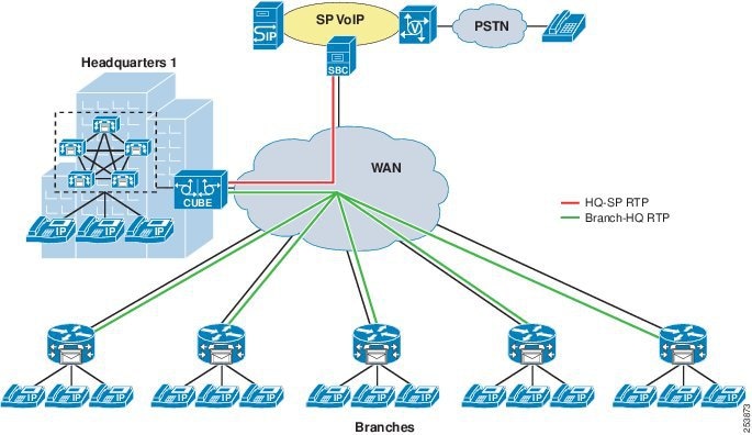
Distributed trunks connect to the service provider through several logical connections. (See Figure 2-26.) Each branch of an enterprise may have its own local trunk to the service provider. Media from branches no longer needs to traverse the WAN but flows to the service provider interface through a local SBC.
Figure 2-26 Distributed SIP Trunk Model
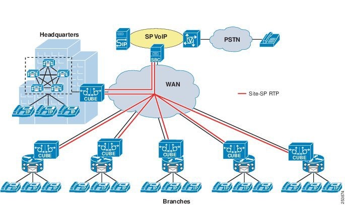
Each connectivity model has its own advantages and disadvantages. Centralized trunks are generally easier to deploy in terms of both physical equipment and configuration complexity. Distributed trunks have the advantage of local hand-off of media and better number portability from local providers. As illustrated in Figure 2-27, a hybrid connectivity model that groups some of the branches together for connectivity, or that provides trunks from each Cisco Unified CM cluster of a multi-cluster deployment, captures the advantages of both forms of deployment.
Figure 2-27 Hybrid SIP Trunk Model with Regional Aggregation
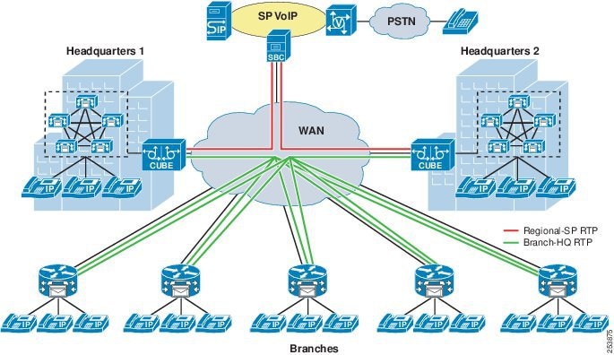
 Feedback