- Preface
- Chapter 1: Digit Translations
- Chapter 2: Routing
- Chapter 3: Local Exchange Routing Guide
- Chapter 4: Electronic Number Mapping and Routing
- Chapter 5: Dial Plans and Routing
- Chapter 6: Command Line Interface Routing
- Chapter 7: Preparing for Dial Plan Provisioning
- Chapter 8: Provisioning Dial Plans
- Appendix A: Call Types and Subtypes
- Glossary
Routing and Dial Plan Guide, Release 6.0.3
Bias-Free Language
The documentation set for this product strives to use bias-free language. For the purposes of this documentation set, bias-free is defined as language that does not imply discrimination based on age, disability, gender, racial identity, ethnic identity, sexual orientation, socioeconomic status, and intersectionality. Exceptions may be present in the documentation due to language that is hardcoded in the user interfaces of the product software, language used based on RFP documentation, or language that is used by a referenced third-party product. Learn more about how Cisco is using Inclusive Language.
- Updated:
- August 24, 2011
Chapter: Chapter 6: Command Line Interface Routing
- Carrier - Service-Provider
- Carrier 9999 Use Dial-Plan "N"
- Carrier All=N
- Carrier All=Y
- Carrier Intra=Y
- Carrier Op-Serv=Y
- Carrier Use Dial-Plan "Y"
- Destination
- Destination Carrier
- Destination InterLATA
- Destination RID
- Destination ROUTE
- Destination SUB
- Dial-Plan
- Dial-Plan Ca-Config
- Dial-Plan "dp50"
- DN2sub
- Dp50 Digit-String=202
- Ea-Use=Y
- In DN2Sub
- LNP Local Sub
- LNP Route
- LNP Trigger=Y
- Not in DN2Sub
- POP 50 Block
- POP 50 No Block
- POP Block-ea=N
- POP Block-ea=Y
- POP Ea-use=N
- POP ITP=Y
- POP LEC-OSS
- Ported-Office-Code in CA
- Ported-Office-Code in CA=N
- Service Provider
- Sub DP Dest InterLATA
- Sub DP Dest IntraLATA
- Subscriber Test1
- Subscriber Test2
- Subsciber and Sub-Profile
- Trunk-grp 6969
Command-Line Interface Routing
Introduction
This chapter provides a basic understanding of how the Cisco BTS 10200 Softswitch command-line interface (CLI) functions with of the routing types and call types. This chapter is divided into the following sections:
•![]() Command-Line Interface Routing Examples
Command-Line Interface Routing Examples
For additional information on call types, refer to "Call Types and Subtypes."
 |
Note |
Routing Types
This section provides the Cisco BTS 10200 CLI routing type information. The following topics are covered in this section:
Basic Subscriber Routing
This section provides a detailed description of the Cisco BTS 10200 basic subscriber routing and provides CLI examples. For detailed information on the CLI, refer to the Cisco BTS 10200 Softswitch CLI Database. Refer to Figure 6-1 for visual representation of basic subscriber routing flow and review the following detailed basic subscriber routing flow.
Step 1 ![]() Subscriber incoming received or placed.
Subscriber incoming received or placed.
Example:
Step 2 ![]() Get the subscriber table (sub-profile identification (ID)).
Get the subscriber table (sub-profile identification (ID)).
Step 3 ![]() Get the subscriber-profile table (dial-plan-identification (DP-ID)).
Get the subscriber-profile table (dial-plan-identification (DP-ID)).
Example:
Step 4 ![]() Go to the dial-plan (based on DP-ID).
Go to the dial-plan (based on DP-ID).
Step 5 ![]() Go to destination table and get the call type and destination.
Go to destination table and get the call type and destination.
Example:
Step 6 ![]() Determine the call type. If the call type is toll free, 900, or 500, proceed to Step 7. If the call type is casual, proceed to Step 8. If the call type is via a presubscribed interexchange carrier (PIC), proceed to Step 9.
Determine the call type. If the call type is toll free, 900, or 500, proceed to Step 7. If the call type is casual, proceed to Step 8. If the call type is via a presubscribed interexchange carrier (PIC), proceed to Step 9.
Examples:
Step 7 ![]() If the call type is toll free, 900, or 500, the Cisco BTS 10200 will use the dial plan to select the call route and to route the call.
If the call type is toll free, 900, or 500, the Cisco BTS 10200 will use the dial plan to select the call route and to route the call.
Step 8 ![]() If the call type is casual, the Cisco BTS 10200 will use the carrier routing information to select the call route and to route the call.
If the call type is casual, the Cisco BTS 10200 will use the carrier routing information to select the call route and to route the call.
Step 9 ![]() If the call type is via a PIC, the Cisco BTS 10200 will user the PIC carrier routing information to select the call route and to route the call.
If the call type is via a PIC, the Cisco BTS 10200 will user the PIC carrier routing information to select the call route and to route the call.
Figure 6-1 Basic Subscriber Routing

Basic Trunk Routing
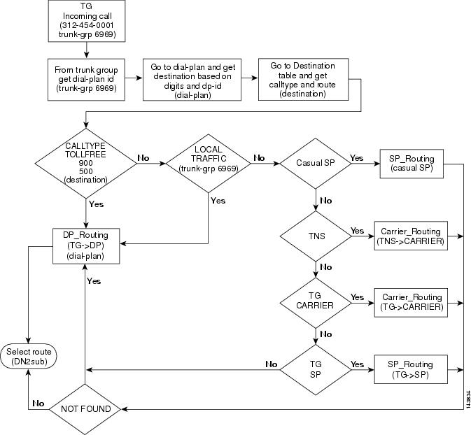
This section provides a detailed description of the Cisco BTS 10200 basic trunk routing and provides CLI examples. For detailed information on the CLI, refer to the Cisco BTS 10200 Softswitch CLI Database. Refer to Figure 6-2 for visual representation of basic trunk routing flow and review the following detailed basic trunk routing flow.
Step 1 ![]() Trunk group (TG) call received or placed.
Trunk group (TG) call received or placed.
Example:
Step 2 ![]() Get the DP-ID from the TG.
Get the DP-ID from the TG.
Example:
Step 3 ![]() Go to the dial-plan and get the destination based on the digits and DP-ID.
Go to the dial-plan and get the destination based on the digits and DP-ID.
Example:
Step 4 ![]() Go to the destination table and get the call type and the route.
Go to the destination table and get the call type and the route.
Example:
Step 5 ![]() Determine the call type. If the call type is toll free, 900, or 500, proceed to Step 6. If the call type is local traffic, proceed to Step 7. If the call type is casual service provider (SP), proceed to Step 8. If the call type is transit network selection (TNS), proceed to Step 9. If the call type is TG carrier, proceed to Step 10. If the call type is TG SP, proceed to Step 11.
Determine the call type. If the call type is toll free, 900, or 500, proceed to Step 6. If the call type is local traffic, proceed to Step 7. If the call type is casual service provider (SP), proceed to Step 8. If the call type is transit network selection (TNS), proceed to Step 9. If the call type is TG carrier, proceed to Step 10. If the call type is TG SP, proceed to Step 11.
Example:
Step 6 ![]() If the call type is toll free, 900, or 500, the Cisco BTS 10200 will use the dial plan to select the call route and to route the call.
If the call type is toll free, 900, or 500, the Cisco BTS 10200 will use the dial plan to select the call route and to route the call.
Examples:
Step 7 ![]() If the call type is local traffic, the Cisco BTS 10200 will use the dial plan to select the call route and to route the call.
If the call type is local traffic, the Cisco BTS 10200 will use the dial plan to select the call route and to route the call.
Examples:
Step 8 ![]() If the call type is casual SP, the Cisco BTS 10200 will use the SP routing to select the call route and to route the call. If the SP routing is not found, the Cisco BTS 10200 will user the dial plan to select the call route and to route the call.
If the call type is casual SP, the Cisco BTS 10200 will use the SP routing to select the call route and to route the call. If the SP routing is not found, the Cisco BTS 10200 will user the dial plan to select the call route and to route the call.
Examples:
Step 9 ![]() If the call type is TNS, the Cisco BTS 10200 will use the carrier routing to select the call route and to select the call route and to route the call. If the carrier routing is not found, the Cisco BTS 10200 will user the dial plan to select the call route and to route the call.
If the call type is TNS, the Cisco BTS 10200 will use the carrier routing to select the call route and to select the call route and to route the call. If the carrier routing is not found, the Cisco BTS 10200 will user the dial plan to select the call route and to route the call.
Examples:
Step 10 ![]() If the call type is TG carrier, the Cisco BTS 10200 will use the carrier routing to select the call route and to route the call. If the carrier routing is not found, the Cisco BTS 10200 will user the dial plan to select the call route and to route the call.
If the call type is TG carrier, the Cisco BTS 10200 will use the carrier routing to select the call route and to route the call. If the carrier routing is not found, the Cisco BTS 10200 will user the dial plan to select the call route and to route the call.
Step 11 ![]() If the call type is TG SP, the Cisco BTS 10200 will the SP routing to select the call route and to route the call. If the SP routing is not found, the Cisco BTS 10200 will user the dial plan to select the call route and to route the call.
If the call type is TG SP, the Cisco BTS 10200 will the SP routing to select the call route and to route the call. If the SP routing is not found, the Cisco BTS 10200 will user the dial plan to select the call route and to route the call.
Examples:
Figure 6-2 Basic Trunk Routing
Carrier Based Routing
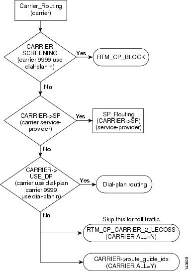
This section provides a detailed description of the Cisco BTS 10200 carrier based routing and provides CLI examples. For detailed information on the CLI, refer to the Cisco BTS 10200 Softswitch CLI Database. Refer to Figure 6-3 for visual representation of carrier based routing flow and review the following detailed carrier based routing flow.
Additionally, LNP-QUERY has been added to the call flow. LNP-QUERY specifies whether to perform a local number portability (LNP) query on the call type. LNP_QUERY applies only if the ALL-CALL-QUERY flag in the LNP-PROFILE table is set to Y and the ACQ-LNP-QUERY token in the Destination table is set to ACQ-BASED-ON-CALL-TYPE. For complete LNP-QUERY details, refer to the Cisco BTS 10200 Softswitch CLI Database and the "NOA Routing (ITU Local Number Portability)" section.
Step 1 ![]() Carrier based routing call is received.
Carrier based routing call is received.
Step 2 ![]() Determine if the carrier is being screened. If the carrier is being screened, proceed to Step 3. If the carrier is not being screened, proceed to Step 4.
Determine if the carrier is being screened. If the carrier is being screened, proceed to Step 3. If the carrier is not being screened, proceed to Step 4.
Example:
Carrier 9999 Use Dial-Plan "N"
Step 3 ![]() If the carrier is being screened, the Cisco BTS 10200 will determine if the carrier call processing is being remotely blocked (RTM_CP_BLOCK). If the carrier call processing is being remotely blocked, the call cannot be completed and will be dropped.
If the carrier is being screened, the Cisco BTS 10200 will determine if the carrier call processing is being remotely blocked (RTM_CP_BLOCK). If the carrier call processing is being remotely blocked, the call cannot be completed and will be dropped.
Step 4 ![]() If the carrier is not being screened, the Cisco BTS 10200 will determine if the carrier is a recognized service provider. If the carrier is a recognized service provider, proceed to Step 5. If the carrier is not a recognized service provider, proceed to Step 6.
If the carrier is not being screened, the Cisco BTS 10200 will determine if the carrier is a recognized service provider. If the carrier is a recognized service provider, proceed to Step 5. If the carrier is not a recognized service provider, proceed to Step 6.
Example:
Step 5 ![]() If the carrier is a recognized service provider, the Cisco BTS 10200 will use the service provider routing to select the call route and to route the call.
If the carrier is a recognized service provider, the Cisco BTS 10200 will use the service provider routing to select the call route and to route the call.
Example:
Step 6 ![]() If the carrier is not a recognized service provider, the Cisco BTS 10200 will determine if a carrier dial plan is configured. If a carrier dial plan is configured, proceed to Step 7. If a carrier dial plan, is not configured proceed to Step 8.
If the carrier is not a recognized service provider, the Cisco BTS 10200 will determine if a carrier dial plan is configured. If a carrier dial plan is configured, proceed to Step 7. If a carrier dial plan, is not configured proceed to Step 8.
Example:
Carrier 9999 Use Dial-Plan "N"
Step 7 ![]() If a carrier dial plan is configured, the Cisco BTS 10200 will use the carrier dial plan to select the call route and to route the call.
If a carrier dial plan is configured, the Cisco BTS 10200 will use the carrier dial plan to select the call route and to route the call.
Step 8 ![]() If a carrier dial plan is not configured, the Cisco BTS 10200 will determine if a carrier remote call processing to local exchange carrier operations support system is available (RTM_CP_CARRIER_2_LECOSS). If the RTM_CP_CARRIER_2_LECOSS is available, proceed to Step 9. If the RTM_CP_CARRIER_2_LECOSS is not available, proceed to Step 10.
If a carrier dial plan is not configured, the Cisco BTS 10200 will determine if a carrier remote call processing to local exchange carrier operations support system is available (RTM_CP_CARRIER_2_LECOSS). If the RTM_CP_CARRIER_2_LECOSS is available, proceed to Step 9. If the RTM_CP_CARRIER_2_LECOSS is not available, proceed to Step 10.
|
Note |
Step 9 ![]() If the RTM_CP_CARRIER_2_LECOSS is available and if the traffic is not toll traffic, the Cisco BTS 10200 will use the RTM_CP_CARRIER_2_LECOSS to select the call route and to route the call.
If the RTM_CP_CARRIER_2_LECOSS is available and if the traffic is not toll traffic, the Cisco BTS 10200 will use the RTM_CP_CARRIER_2_LECOSS to select the call route and to route the call.
Example:
Step 10 ![]() If the RTM_CP_CARRIER_2_LECOSS is not available, the Cisco BTS 10200 will use the carrier guide index to select the call route and to route the call.
If the RTM_CP_CARRIER_2_LECOSS is not available, the Cisco BTS 10200 will use the carrier guide index to select the call route and to route the call.
Example:
Figure 6-3 Carrier Based Routing
Basic Dial Plan Routing
This section provides a detailed description of the Cisco BTS 10200 basic dial plan routing and provides CLI examples. For detailed information on the CLI, refer to the Cisco BTS 10200 Softswitch CLI Database. Refer to Figure 6-4 for visual representation of basic dial plan routing flow and review the following detailed basic dial plan routing flow.
Step 1 ![]() Basic dial plan routing call received.
Basic dial plan routing call received.
Step 2 ![]() Determine if the nature of address (NOA) for the received call is an international call. If the call is an international call, the Cisco BTS 10200 uses the international dial plan to select the call route and to route the call. If the call is not an international call, proceed to Step 3.
Determine if the nature of address (NOA) for the received call is an international call. If the call is an international call, the Cisco BTS 10200 uses the international dial plan to select the call route and to route the call. If the call is not an international call, proceed to Step 3.
Example:
Step 3 ![]() Determine if the call destination is found. If the call destination is not found, the Cisco BTS 10200 returns a destination not found response (not found) and drops the call. If the call destination is found, proceed to Step 4.
Determine if the call destination is found. If the call destination is not found, the Cisco BTS 10200 returns a destination not found response (not found) and drops the call. If the call destination is found, proceed to Step 4.
Step 4 ![]() Determine if a call destination subscriber is found. If a call destination subscriber is found, the Cisco BTS 10200 returns a subscriber (SUB) response and uses the subscriber information to select the call route and to route the call. If a call destination subscriber is not found, proceed to Step 5.
Determine if a call destination subscriber is found. If a call destination subscriber is found, the Cisco BTS 10200 returns a subscriber (SUB) response and uses the subscriber information to select the call route and to route the call. If a call destination subscriber is not found, proceed to Step 5.
Example:
Step 5 ![]() Determine if a call destination route is found. If a call destination route is found, the Cisco BTS 10200 returns a destination (DEST) response and uses the route guide index to select the call route and to route the call. If a call destination route is not found, proceed to Step 6.
Determine if a call destination route is found. If a call destination route is found, the Cisco BTS 10200 returns a destination (DEST) response and uses the route guide index to select the call route and to route the call. If a call destination route is not found, proceed to Step 6.
Example:
Step 6 ![]() Determine if a call destination route identification (RID) is found. If a call destination RID is found, the Cisco BTS 10200 returns a DEST response and uses the route index to select the call route and to route the call. If a call destination RID is not found, proceed to Step 7.
Determine if a call destination route identification (RID) is found. If a call destination RID is found, the Cisco BTS 10200 returns a DEST response and uses the route index to select the call route and to route the call. If a call destination RID is not found, proceed to Step 7.
Example:
Step 7 ![]() Determine if a destination carrier is found. If a destination carrier is found, proceed to the Step 8. If a destination carrier is not found, the Cisco BTS 10200 returns an error and drops the call.
Determine if a destination carrier is found. If a destination carrier is found, proceed to the Step 8. If a destination carrier is not found, the Cisco BTS 10200 returns an error and drops the call.
Example:
Step 8 ![]() Determine the call type. If the call type is toll free, 900, or 500, the Cisco BTS 10200 selects the call route and routes the call using the destination carrier routing. If the call type is not toll free, 900, or 500, the Cisco BTS 10200 returns an error and drops the call.
Determine the call type. If the call type is toll free, 900, or 500, the Cisco BTS 10200 selects the call route and routes the call using the destination carrier routing. If the call type is not toll free, 900, or 500, the Cisco BTS 10200 returns an error and drops the call.
Figure 6-4 Basic Dial Plan Routing

Cluster Routing
This section provides an overview of CLI commands that you need to implement the Cluster Network/Routing supported by the Cisco BTS 10200 in Release 5.0.
The CLI commands provided in the following sections are not in any particular sequence, and could be executed in any order as long as dependencies of the table in question are already in place. The main intention of this document is to summarize the CLI commands that would be needed to implement cluster networking.
Creating a Cluster Network with Three CMS/MGCs
Figure 6-5 illustrates creation of a cluster network with three CMS/MGCs.
Figure 6-5 Creating a Cluster Network with Three CMS/MGC
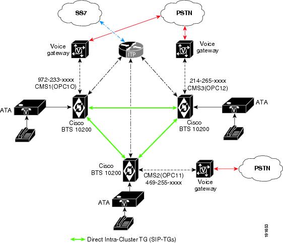
1. ![]() Clustering requires switches to have their individual point codes and here we are assuming the existing three switches to already have point codes of OPC10, OPC11 and OPC12.
Clustering requires switches to have their individual point codes and here we are assuming the existing three switches to already have point codes of OPC10, OPC11 and OPC12.
2. ![]() The Cisco BTS 10200 switches have an Intra-cluster TG (SIP TG) connected between each of them as shown in the diagram. (Basically each CMS/MGC in the network needs to have direct connectivity with the other switches.)
The Cisco BTS 10200 switches have an Intra-cluster TG (SIP TG) connected between each of them as shown in the diagram. (Basically each CMS/MGC in the network needs to have direct connectivity with the other switches.)
add trunk-grp id=sip_1_2 ;tg-type=sip;dial-plan-id=cluster-dial-plan;
tsap-addr=CMS2;
add trunk-grp id=sip_1_3 ;tg-type=sip;dial-plan-id=cluster-dial-plan;
tsap-addr=CMS3;
add trunk-grp id=sip_2_3 ;tg-type=sip;dial-plan-id=cluster-dial-plan;
tsap-addr=CMS3;
add trunk-grp id=sip_2_1 ;tg-type=sip;dial-plan-id=cluster-dial-plan;
tsap-addr=CMS1;
add trunk-grp id=sip_3_1 ;tg-type=sip;dial-plan-id=cluster-dial-plan;
tsap-addr=CMS1;
add trunk-grp id=sip_3_2 ;tg-type=sip;dial-plan-id=cluster-dial-plan;
tsap-addr=CMS2;
Make sure the POI flag in the trunk-grp table for each of the trunk-grp's added above is set to INTRA-CLUSTER.
3. ![]() Decide on a CLRN (assuming it to be 972-999-9999 in this case) and provision the CLRN into each of the CMS/MGCs. The CLRN also needs to be registered in the LNP database.
Decide on a CLRN (assuming it to be 972-999-9999 in this case) and provision the CLRN into each of the CMS/MGCs. The CLRN also needs to be registered in the LNP database.
On CMS1/CMS2/CMS3:
add ndc digit-string=972;
add exchange-code ndc=972;ec=999;office-code-index=1;
add office-code ndc=972;ec=999;call-agent-id=CA146;dn-group=xxxx;
add dn2subscriber office_code_index=1;dn=9999;status=CLRN;
4. ![]() Each CMS/MGC needs to have a separate NPA-NXX.
Each CMS/MGC needs to have a separate NPA-NXX.
This basically means each CMS needs to handle a separate NPA-NXX, so as shown in the diagram we have CMS1 handling 972-233, CMS2 handling 469-255 and CMS3 handling 214-265.
5. ![]() Provision the cluster dial plan (NPA-NXX routing) in each of the CMS/MGCs to reach each other.
Provision the cluster dial plan (NPA-NXX routing) in each of the CMS/MGCs to reach each other.
On CMS1:
add cluster-dial-plan-profile id=cdpp;
add route id=CMS3;tgn1_id=sip_1_3;
add route id=CMS2;tgn1_id=sip_1_2;
add destination dest-id=CMS3;route-type=ROUTE-ID;route-id=CMS3;call-type=LOCAL;
add destination dest-id=CMS2;route-type=ROUTE-ID;route-id=CMS2;call-type=LOCAL;
add dial-plan id=cdpp;digit-string=214-265;dest-id=CMS3;
add dial-plan id=cdpp;digit-string=469-255;dest-id=CMS2;
add ca-config;cluster-dial-plan id=cdpp;
For CMS2:
add cluster-dial-plan-profile id=cdpp;
add route id=CMS1;tgn1_id=sip_2_1;
add route id=CMS3;tgn1_id=sip_2_3;
add destination dest-id=CMS1;route-type=ROUTE-ID;route-id=CMS1;call-type=LOCAL;
add destination dest-id=CMS3;route-type=ROUTE-ID;route-id=CMS3;call-type=LOCAL;
add dial-plan id=cdpp;digit-string=972-233;dest-id=CMS1;
add dial-plan id=cdpp;digit-string=214-265;dest-id=CMS3;
add ca-config;cluster-dial-plan id=cdpp;
For CMS3:
add cluster-dial-plan-profile id=cdpp;
add route id=CMS1;tgn1_id=sip_3_1;
add route id=CMS2;tgn1_id=sip_3_2;
add destination dest-id=CMS1;route-type=ROUTE-ID;route-id=CMS1;call-type=local;
add destination dest-id=CMS2;route-type=ROUTE-ID;route-id=CMS2;call-type=local;
add dial-plan id=cdpp;digit-string=972-233;dest-id=CMS1;
add dial-plan id=cdpp;digit-string=469-255;dest-id=CMS2;
add ca-config;cluster-dial-plan id=cdpp;
Ported-In Sub from PSTN into CMS1
Imagine a subscriber from PSTN (972-384-1234) ported into one of the CMSs in the cluster—say CMS1. If a subscriber on any of the CMSs makes a call to that ported number this is the provisioning needed.
On CMS1:
add ported-office-code digit-string=972-384;
add dn2subscriber office-code-index=1;dn=1234;;status=assigned;lnp_trigger=y;
On CMS2:
add ported-office-code digit-string=972-384;
add dial-plan id=cdpp;digit-string=972-384;dest-id=CMS1;
On CMS3:
add ported-office-code digit-string=972-384;
add dial-plan id=cdpp;digit-string=972-384;dest-id=CMS1;
If the call comes in from the PSTN for this ported number, it would have already come in with a CLRN number. It depends on which CMS in the cluster receives the call ffirst. Assume that CMS3 received the call (since it's a CLRN), CMS3 would look up the GAP and route the call to CMS1 as specified in the cluster dial plan entries.
Adding One More CMS/MGC to a Cluster Network
Figure 6-6 illustrates adding one more CMS/MGC to a cluster network.
Figure 6-6 Adding One More CMS/MGC to the Cluster Network

1. ![]() Assign separate point codes for the new CMS/MGC switch.
Assign separate point codes for the new CMS/MGC switch.
add opc id=13; point-code=4-4-4; description=CMS 04 ; (On CMS4)
add dpc id=PSTN;point-code=x-x-x; description= PSTN conn from CMS4;
2. ![]() Have an Intra-cluster TG (SIP TG) connected between each of them as shown in the diagram.
Have an Intra-cluster TG (SIP TG) connected between each of them as shown in the diagram.
On CMS4:
add trunk-grp id=sip_4_1 ;tg-type=sip;dial-plan-id=cluster-dial-plan; tsap-addr=CMS1;
add trunk-grp id=sip_4_2 ;tg-type=sip;dial-plan-id=cluster-dial-plan; tsap-addr=CMS2;
add trunk-grp id=sip_4_3 ;tg-type=sip;dial-plan-id=cluster-dial-plan; tsap-addr=CMS3;
On CMS1:
add trunk-grp id=sip_1_4 ;tg-type=sip;dial-plan-id=cluster-dial-plan; tsap-addr=CMS4;
On CMS2:
add trunk-grp id=sip_2_4 ;tg-type=sip;dial-plan-id=cluster-dial-plan; tsap-addr=CMS4;
On CMS3:
add trunk-grp id=sip_3_4 ;tg-type=sip;dial-plan-id=cluster-dial-plan; tsap-addr=CMS4;
3. ![]() Add an entry in dn2sub table for the CLRN of the cluster which is 972-999-9999.
Add an entry in dn2sub table for the CLRN of the cluster which is 972-999-9999.
add ndc digit-string=972;
add exchange-code ndc=972;ec=999;office-code-index=1;
add office-code ndc=972;ec=999;call-agent-id=CA146;dn-group=xxxx;
add dn2subscriber office_code_index=1;dn=9999;status=CLRN;
4. ![]() Each switch needs to have its own NPA-NXX, so let's assume CMS4 handles 972-682-xxxx.
Each switch needs to have its own NPA-NXX, so let's assume CMS4 handles 972-682-xxxx.
5. ![]() Provision the cluster dial plan (NPA-NXX routing) in each of the CMS/MGC switches to reach the others.
Provision the cluster dial plan (NPA-NXX routing) in each of the CMS/MGC switches to reach the others.
On CMS4:
add cluster-dial-plan-profile id=cdpp;
add route id=CMS1;tgn1_id=sip_4_1;
add route id=CMS2;tgn1_id=sip_4_2;
add route id=CMS3;tgn1_id=sip_4_3;
add destination dest-id=CMS1;route-type=ROUTE-ID;route-id=CMS1;call-type=local;
add destination dest-id=CMS2;route-type=ROUTE-ID;route-id=CMS2;call-type=local;
add destination dest-id=CMS3;route-type=ROUTE-ID;route-id=CMS3;call-type=local;
add dial-plan id=cdpp;digit-string=972-233;dest-id=CMS1;
add dial-plan id=cdpp;digit-string=469-255;dest-id=CMS2;
add dial-plan id=cdpp;digit-string=214-265;dest-id=CMS3;
add ca-config;cluster-dial-plan id=cdpp;
On CMS1:
add route id=CMS4;tgn1_id=sip_1_4;
add destination dest-id=CMS4;route-type=ROUTE-ID;route-id=CMS4;call-type=local;
add dial-plan id=cdpp;digit-string=972-682;dest-id=CMS4;
On CMS2:
add route id=CMS4;tgn1_id=sip_2_4;
add destination dest-id=CMS4;route-type=ROUTE-ID;route-id=CMS4;call-type=local;
add dial-plan id=cdpp;digit-string=972-682;dest-id=CMS4;
On CMS3:
add route id=CMS4;tgn1_id=sip_3_4;
add destination dest-id=CMS4;route-type=ROUTE-ID;route-id=CMS4;call-type=local;
add dial-plan id=cdpp;digit-string=972-682;dest-id=CMS4;
Call Types
This section provides detailed information on CLI usage for the Cisco BTS 10200 call types. CLI information on the following call types is provided:
For additional information on call types, refer to "Call Types and Subtypes."
1+ InterLATA Call
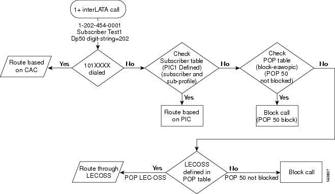
This section describes the Cisco BTS 10200 routing and call flow for 1+ interLATA calls and provides some CLI examples. For information on the CLI, refer to the Cisco BTS 10200 Softswitch CLI Database. Refer to Figure 6-7 for visual representation of the 1+ interLATA call routing flow and review the following detailed 1+ interLATA call routing flow.
Step 1 ![]() A 1+ interLATA call is received.
A 1+ interLATA call is received.
Examples:
Step 2 ![]() Determine if a 101XXXX number has been dialed. If a 101XXXX number has been dialed, the Cisco BTS 10200 selects the call route and routes the call based on the carrier access code (CAC). If a 101XXXX number has not been dialed, proceed to Step 3.
Determine if a 101XXXX number has been dialed. If a 101XXXX number has been dialed, the Cisco BTS 10200 selects the call route and routes the call based on the carrier access code (CAC). If a 101XXXX number has not been dialed, proceed to Step 3.
Step 3 ![]() Check the subscriber table to determine if a PIC is defined. If a PIC is defined, the Cisco BTS 10200 selects the call route and routes the call based on the PIC information. If a PIC is not defined, proceed to Step 4.
Check the subscriber table to determine if a PIC is defined. If a PIC is defined, the Cisco BTS 10200 selects the call route and routes the call based on the PIC information. If a PIC is not defined, proceed to Step 4.
Example:
Step 4 ![]() Check the point of presence (POP) table. If a block-eawopic is configured, the Cisco BTS 10200 blocks the call. If a block-eawopic is not configured, proceed to Step 5.
Check the point of presence (POP) table. If a block-eawopic is configured, the Cisco BTS 10200 blocks the call. If a block-eawopic is not configured, proceed to Step 5.
Examples:
Step 5 ![]() Determine if a local exchange carrier operations support system (LECOSS) is defined in the POP table. If a LECOSS is defined in the POP table, the Cisco BTS 10200 selects to route the call through use of the LECOSS. If a LECOSS is not defined in the POP table, the Cisco BTS 10200 blocks the call.
Determine if a local exchange carrier operations support system (LECOSS) is defined in the POP table. If a LECOSS is defined in the POP table, the Cisco BTS 10200 selects to route the call through use of the LECOSS. If a LECOSS is not defined in the POP table, the Cisco BTS 10200 blocks the call.
Examples:
Figure 6-7 1+ InterLATA Call
1+ IntraLATA Call
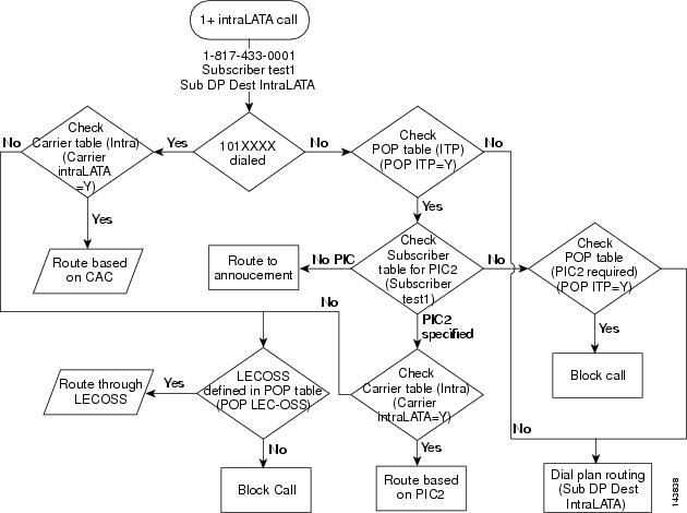
This section provides a detailed description of the Cisco BTS 10200 routing and call flow for 1+ intraLATA calls and provides some CLI examples. For information on the CLI, refer to the Cisco BTS 10200 Softswitch CLI Database. Refer to Figure 6-8 for visual representation of the 1+ intraLATA call routing flow and review the following detailed 1+ intraLATA call routing flow.
Step 1 ![]() An 1+ intraLATA call is received.
An 1+ intraLATA call is received.
Examples:
Step 2 ![]() Determine if 101XXXX number has been dialed. If a 101XXXX number has been dialed, proceed to Step 3. If a 101XXXX number has not been dialed, proceed to Step 4.
Determine if 101XXXX number has been dialed. If a 101XXXX number has been dialed, proceed to Step 3. If a 101XXXX number has not been dialed, proceed to Step 4.
Step 3 ![]() Check the Carrier table for a CAC. If a CAC is available, the Cisco BTS 10200 selects the call route and route the call based on the CAC. If a CAC is not available, proceed to Step 3a.
Check the Carrier table for a CAC. If a CAC is available, the Cisco BTS 10200 selects the call route and route the call based on the CAC. If a CAC is not available, proceed to Step 3a.
Example:
Determine if a LECOSS is defined in the POP table. If a LECOSS is defined in the POP table, the Cisco BTS 10200 selects the call route and routes the call through use of the LECOSS. If a LECOSS is not defined in the POP table, the Cisco BTS 10200 blocks the call.
Step 4 ![]() Check the POP table for a configured IP transfer point (ITP). If an ITP is configured, proceed to Step 4a. If an ITP is not configured, the Cisco BTS 10200 routes the call through use of the dial plan routing.
Check the POP table for a configured IP transfer point (ITP). If an ITP is configured, proceed to Step 4a. If an ITP is not configured, the Cisco BTS 10200 routes the call through use of the dial plan routing.
Example:
a. ![]() Check the subscriber table for a specified PIC. If a PIC is specified, proceed to Step 4b. If a PIC is not specified, the Cisco BTS 10200 routes the call to the announcement server and checks the POP table for a specified PIC. If a PIC is not specified, the Cisco BTS 10200 blocks the call or if a dial plan is available, the Cisco BTS 10200 selects the call route and routes the call according to the dial plan routing information.
Check the subscriber table for a specified PIC. If a PIC is specified, proceed to Step 4b. If a PIC is not specified, the Cisco BTS 10200 routes the call to the announcement server and checks the POP table for a specified PIC. If a PIC is not specified, the Cisco BTS 10200 blocks the call or if a dial plan is available, the Cisco BTS 10200 selects the call route and routes the call according to the dial plan routing information.
Examples:
b. ![]() Check the intra-carrier table for a specified PIC. If a PIC is specified in the intra-carrier table, the Cisco BTS 10200 selects the call route and routes the call based on the PIC information. If a PIC is not specified in the intra-carrier table, proceed to Step 4c.
Check the intra-carrier table for a specified PIC. If a PIC is specified in the intra-carrier table, the Cisco BTS 10200 selects the call route and routes the call based on the PIC information. If a PIC is not specified in the intra-carrier table, proceed to Step 4c.
Example:
c. ![]() Determine if a LECOSS is defined in the POP table. If a LECOSS is defined in the POP table, the Cisco BTS 10200 selects the call route and routes the call through the LECOSS. If a LECOSS is not defined in the POP table, the Cisco BTS 10200 blocks the call.
Determine if a LECOSS is defined in the POP table. If a LECOSS is defined in the POP table, the Cisco BTS 10200 selects the call route and routes the call through the LECOSS. If a LECOSS is not defined in the POP table, the Cisco BTS 10200 blocks the call.
Example:
Figure 6-8 1+ IntraLATA Call
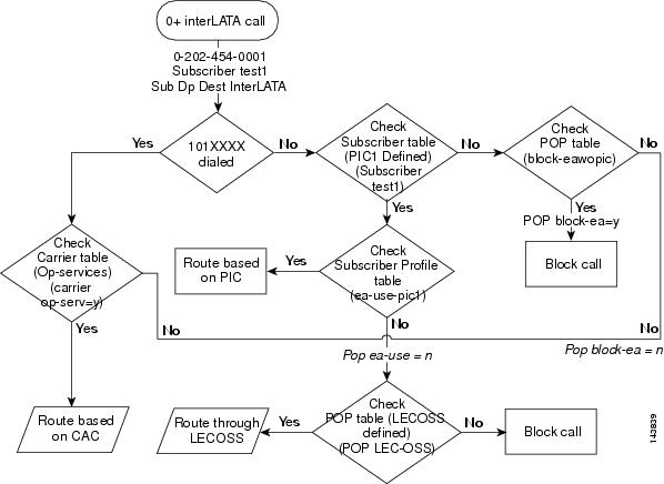
0+ InterLATA Call
This section describes the Cisco BTS 10200 routing and call flow for 0+ interLATA calls and provides CLI examples. For detailed information on the CLI, refer to the Cisco BTS 10200 Softswitch CLI Database. Refer to Figure 6-9 for visual representation of the 0+ interLATA call routing flow and review the following detailed 0+ interLATA call routing flow.
Step 1 ![]() A 0+ interLATA call is received.
A 0+ interLATA call is received.
Examples:
Step 2 ![]() Determine if a 101XXXX number has been dialed. If a 101XXXX number has been dialed proceed to Step 3. If a 101XXXX number has not been dialed, proceed to Step 5.
Determine if a 101XXXX number has been dialed. If a 101XXXX number has been dialed proceed to Step 3. If a 101XXXX number has not been dialed, proceed to Step 5.
Step 3 ![]() Check the Carrier table for a CAC. If a CAC is available, the Cisco BTS 10200 selects the call route and routes the call based on the CAC. If a CAC is not available, proceed to Step 4.
Check the Carrier table for a CAC. If a CAC is available, the Cisco BTS 10200 selects the call route and routes the call based on the CAC. If a CAC is not available, proceed to Step 4.
Example:
Step 4 ![]() Check the POP table for a defined LECOSS. If a LECOSS is defined in the POP table, the Cisco BTS 10200 routes the call through the LECOSS. If a LECOSS is not defined in the POP table, the Cisco BTS 10200 blocks the call.
Check the POP table for a defined LECOSS. If a LECOSS is defined in the POP table, the Cisco BTS 10200 routes the call through the LECOSS. If a LECOSS is not defined in the POP table, the Cisco BTS 10200 blocks the call.
Example:
Step 5 ![]() Check the subscriber table for a defined PIC. If a PIC is defined in the subscriber table, proceed to Step 6. If a PIC is not defined in the subscriber table, proceed to Step 7.
Check the subscriber table for a defined PIC. If a PIC is defined in the subscriber table, proceed to Step 6. If a PIC is not defined in the subscriber table, proceed to Step 7.
Example:
Step 6 ![]() Check the subscriber profile for an ea-use-pic entry. If the subscriber profile contains an ea-use-pic entry, the Cisco BTS 10200 selects the call route and routes the call based on the PIC information. If the subscriber profile does not contain an ea-use-pic entry, return to Step 4.
Check the subscriber profile for an ea-use-pic entry. If the subscriber profile contains an ea-use-pic entry, the Cisco BTS 10200 selects the call route and routes the call based on the PIC information. If the subscriber profile does not contain an ea-use-pic entry, return to Step 4.
Examples:
Step 7 ![]() Check the POP table for a block-eawopic entry. If the POP table contains a block-eawopic entry, the Cisco BTS 10200 blocks the call. If the POP table does not contain a block-eawopic entry, return to Step 4.
Check the POP table for a block-eawopic entry. If the POP table contains a block-eawopic entry, the Cisco BTS 10200 blocks the call. If the POP table does not contain a block-eawopic entry, return to Step 4.
Examples:
Figure 6-9 0+ InterLATA Call
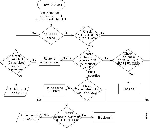
0+ IntraLATA Call
This section describes the Cisco BTS 10200 routing and call flow for 0+ intraLATA calls and provides CLI examples. For information about the CLI, refer to the Cisco BTS 10200 Softswitch CLI Database. Refer to Figure 6-10 for visual representation of the 0+ intraLATA call routing flow and review the following detailed 0+ intraLATA call routing flow.
Step 1 ![]() A 0+ intraLATA call is received.
A 0+ intraLATA call is received.
Examples:
Step 2 ![]() Determine if a 101XXXX number was dialed. If a 101XXXX number was dialed, proceed to Step 3. If a 101XXXX number was not dialed, proceed to Step 5.
Determine if a 101XXXX number was dialed. If a 101XXXX number was dialed, proceed to Step 3. If a 101XXXX number was not dialed, proceed to Step 5.
Step 3 ![]() Check the Carrier table for a CAC. If a CAC is available, the Cisco BTS 10200 selects the call route and routes the call based on the CAC. If a CAC is not available, proceed to Step 4.
Check the Carrier table for a CAC. If a CAC is available, the Cisco BTS 10200 selects the call route and routes the call based on the CAC. If a CAC is not available, proceed to Step 4.
Example:
Step 4 ![]() Check the POP table for a defined LECOSS. If a LECOSS is defined in the POP table, the Cisco BTS 10200 routes the call through the LECOSS. If a LECOSS is not defined in the POP table, the Cisco BTS 10200 blocks the call.
Check the POP table for a defined LECOSS. If a LECOSS is defined in the POP table, the Cisco BTS 10200 routes the call through the LECOSS. If a LECOSS is not defined in the POP table, the Cisco BTS 10200 blocks the call.
Example:
Step 5 ![]() Check the POP table for a configured ITP. If an ITP is configured, proceed to Step 6. If an ITP is not configured return to Step 4.
Check the POP table for a configured ITP. If an ITP is configured, proceed to Step 6. If an ITP is not configured return to Step 4.
Example:
Step 6 ![]() Check the subscriber table for a specified PIC. If a PIC is specified, proceed to Step 7. If a PIC is not specified, the Cisco BTS 10200 routes the call to the announcement server. Additionally, if a PIC is not specified in the subscriber table, the Cisco BTS 10200 checks the POP table for a specified PIC. If a PIC is specified in the POP table, the Cisco BTS 10200 blocks the call. If a PIC is not specified in the POP table, return to Step 4.
Check the subscriber table for a specified PIC. If a PIC is specified, proceed to Step 7. If a PIC is not specified, the Cisco BTS 10200 routes the call to the announcement server. Additionally, if a PIC is not specified in the subscriber table, the Cisco BTS 10200 checks the POP table for a specified PIC. If a PIC is specified in the POP table, the Cisco BTS 10200 blocks the call. If a PIC is not specified in the POP table, return to Step 4.
Examples:
Step 7 ![]() Check the intra-carrier table for the specified PIC. If the specified PIC is included in the intra-carrier table, the Cisco BTS 10200 selects the call route and routes the call based on the PIC information. If the specified PIC is not included in the intra-carrier table, return to Step 4.
Check the intra-carrier table for the specified PIC. If the specified PIC is included in the intra-carrier table, the Cisco BTS 10200 selects the call route and routes the call based on the PIC information. If the specified PIC is not included in the intra-carrier table, return to Step 4.
Example:
Figure 6-10 0+ IntraLATA Call
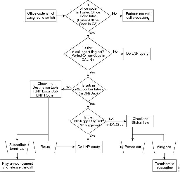
Ported-In Call Processing
This section describes the Cisco BTS 10200 routing and call flow for ported-in call processing calls and provides CLI examples. For information on the CLI, refer to the Cisco BTS 10200 Softswitch CLI Database. Refer to Figure 6-11 for visual representation of the ported-in call processing call routing flow and review the following detailed ported-in call processing call routing flow.
Step 1 ![]() A ported-in call is received.
A ported-in call is received.
Step 2 ![]() The office code is not assigned to the Cisco BTS 10200.
The office code is not assigned to the Cisco BTS 10200.
Step 3 ![]() Determine if the office code is in the ported-in office code table. If the office code is in the ported-in office code table, proceed to Step 4. if the office code is not in the ported-in office code table, perform normal call processing.
Determine if the office code is in the ported-in office code table. If the office code is in the ported-in office code table, proceed to Step 4. if the office code is not in the ported-in office code table, perform normal call processing.
Example:
Step 4 ![]() Determine if the in-call agent flag is set. If the in-call agent flag is set, proceed to Step 5. If the in-call agent flag is not set, the Cisco BTS 10200 performs a local number portability (LNP) query.
Determine if the in-call agent flag is set. If the in-call agent flag is set, proceed to Step 5. If the in-call agent flag is not set, the Cisco BTS 10200 performs a local number portability (LNP) query.
Examples:
Step 5 ![]() Determine if the subscriber is included in the dn2subscriber table. If the subscriber is included in the dn2sunscriber table, proceed to Step 6. If the subscriber is not included in the dn2subscriber table, proceed to Step 7.
Determine if the subscriber is included in the dn2subscriber table. If the subscriber is included in the dn2sunscriber table, proceed to Step 6. If the subscriber is not included in the dn2subscriber table, proceed to Step 7.
Examples:
Step 6 ![]() Determine if the LNP trigger flag is set. If the LNP trigger flag is set, the Cisco BTS 10200 performs a LNP query and ports out the call. If the LNP trigger flag is not set, the Cisco BTS 10200 checks the status field to determine if an LNP trigger has been assigned and ports out the call or terminates the call to the subscriber.
Determine if the LNP trigger flag is set. If the LNP trigger flag is set, the Cisco BTS 10200 performs a LNP query and ports out the call. If the LNP trigger flag is not set, the Cisco BTS 10200 checks the status field to determine if an LNP trigger has been assigned and ports out the call or terminates the call to the subscriber.
Examples:
Step 7 ![]() Check the destination table for the subscriber information. Based on the destination table information, the Cisco BTS 10200 routes the call or issues a subscriber terminator, releases the call, and plays the released call announcement. As part of routing the call, the Cisco BTS 10200 performs an LNP query and, if necessary, ports out the call.
Check the destination table for the subscriber information. Based on the destination table information, the Cisco BTS 10200 routes the call or issues a subscriber terminator, releases the call, and plays the released call announcement. As part of routing the call, the Cisco BTS 10200 performs an LNP query and, if necessary, ports out the call.
Examples:
Figure 6-11 Ported-In Call Processing
Command-Line Interface Routing Examples
This section provides the following CLI routing examples:
•![]() Carrier 9999 Use Dial-Plan "N"
Carrier 9999 Use Dial-Plan "N"
Carrier - Service-Provider
The following Carrier - Service-Provider CLI example is used in the Carrier Based Routing example.
CLI>show carrier id=7777
Reply : Success: Entry 1 of 1 returned.
ID=7777
STATUS=INS
INTER=Y
INTRA=N
INTL=N
CASUAL=Y
CUT_THRU=Y
OP_SERVICES=Y
SEND_CN=N
SEND_CSP=N
USE_DIAL_PLAN=N
ROUTE_GUIDE_ID=test
SP_ID=test
NETWORK_TYPE=NOTUSED
NATIONAL_NETWORK_PLAN=NOTUSED
Carrier 9999 Use Dial-Plan "N"
The following Carrier 9999 Use Dial-Plan "N" CLI example is used in the Carrier Based Routing example.
CLI>show carrier id=9999
Reply : Success: Entry 1 of 1 returned.
ID=9999
STATUS=INS
INTER=Y
INTRA=N
INTL=N
CASUAL=Y
CUT_THRU=Y
OP_SERVICES=Y
SEND_CN=N
SEND_CSP=N
USE_DIAL_PLAN=N
NETWORK_TYPE=NOTUSED
NATIONAL_NETWORK_PLAN=NOTUSED
Carrier All=N
The following Carrier All=N CLI example is used in the Carrier Based Routing example.
CLI>show carrier id=7777
Reply : Success: Entry 1 of 1 returned.
ID=7777
STATUS=INS
INTER=N
INTRA=N
INTL=N
CASUAL=N
CUT_THRU=N
OP_SERVICES=N
SEND_CN=N
SEND_CSP=N
USE_DIAL_PLAN=N
ROUTE_GUIDE_ID=test
NETWORK_TYPE=NOTUSED
NATIONAL_NETWORK_PLAN=NOTUSED
Carrier All=Y
The following Carrier All=Y CLI example is used in the Carrier Based Routing example.
CLI>show carrier id=7777
Reply : Success: Entry 1 of 1 returned.
ID=7777
STATUS=INS
INTER=Y
INTRA=Y
INTL=Y
CASUAL=Y
CUT_THRU=Y
OP_SERVICES=Y
SEND_CN=N
SEND_CSP=N
USE_DIAL_PLAN=N
ROUTE_GUIDE_ID=TEST
NETWORK_TYPE=NOTUSED
NATIONAL_NETWORK_PLAN=NOTUSED
Carrier Intra=Y
The following Carrier Intra=Y CLI example is used in the 1+ IntraLATA Call and 0+ IntraLATA Call routing examples.
CLI>show carrier id=9999
Reply : Success: Entry 1 of 1 returned.
ID=9999
STATUS=INS
INTER=Y
INTRA=Y
INTL=N
CASUAL=Y
CUT_THRU=Y
OP_SERVICES=Y
SEND_CN=N
SEND_CSP=N
USE_DIAL_PLAN=Y
NETWORK_TYPE=NOTUSED
NATIONAL_NETWORK_PLAN=NOTUSED
Carrier Op-Serv=Y
The following Carrier Op-Serv=Y CLI example is used in the 0+ InterLATA Call and 0+ IntraLATA Call routing examples.
CLI>show carrier id=7777
Reply : Success: Entry 1 of 1 returned.
ID=7777
STATUS=INS
INTER=Y
INTRA=N
INTL=N
CASUAL=Y
CUT_THRU=Y
OP_SERVICES=Y
SEND_CN=N
SEND_CSP=N
USE_DIAL_PLAN=N
ROUTE_GUIDE_ID=TEST
SP_ID=test
NETWORK_TYPE=NOTUSED
NATIONAL_NETWORK_PLAN=NOTUSED
Carrier Use Dial-Plan "Y"
The following Carrier Use Dial-Plan "Y" CLI example is used in the Carrier Based Routing example.
CLI>show carrier id=8888
Reply : Success: Entry 1 of 1 returned.
ID=8888
STATUS=INS
INTER=Y
INTRA=N
INTL=N
CASUAL=Y
CUT_THRU=Y
OP_SERVICES=Y
SEND_CN=N
SEND_CSP=N
USE_DIAL_PLAN=Y
DESCRIPTION=TEST
NETWORK_TYPE=NOTUSED
NATIONAL_NETWORK_PLAN=NOTUSED
Destination
The following Destination CLI example is used in the Basic Subscriber Routing example and the Basic Trunk Routing example.
CLI>show destination
DEST_ID=local-sub
CALL_TYPE=LOCAL
ROUTE_TYPE=SUB
ZERO_PLUS=N
INTRA_STATE=Y
GAP_ROUTING=N
Destination Carrier
The following Destination Carrier CLI example is used in the Basic Dial Plan Routing example.
CLI>show destination dest-id=800;
Reply : Success: Entry 1 of 1 returned.
DEST_ID=800
CALL_TYPE=TOLL_FREE
ROUTE_TYPE=CARRIER
CARRIER_ID=7777
ZERO_PLUS=N
INTRA_STATE=Y
GAP_ROUTING=N
Destination InterLATA
The following Destination interLATA CLI example is used in the 1+ InterLATA Call routing example.
CLI>show destination dest-id=interLATA
Reply : Success: Entry 1 of 1 returned.
DEST_ID=interLATA
CALL_TYPE=interLATA
ROUTE_TYPE=ROUTE
ROUTE_GUIDE_ID=TEST
ZERO_PLUS=N
INTRA_STATE=Y
GAP_ROUTING=N
Destination RID
The following Destination RID CLI example is used in the Basic Dial Plan Routing example.
CLI>show destination dest-id=65019
Reply : Success: Entry 1 of 1 returned.
DEST_ID=65019
CALL_TYPE=LOCAL
ROUTE_TYPE=RID
ZERO_PLUS=N
INTRA_STATE=Y
ROUTE_ID=65019
GAP_ROUTING=N
Destination ROUTE
The following Destination ROUTE CLI example is used in the Basic Dial Plan Routing example.
CLI>show destination dest-id=65019
Reply : Success: Entry 1 of 1 returned.
DEST_ID=65019
CALL_TYPE=LOCAL
ROUTE_TYPE=ROUTE
ROUTE_GUIDE_ID=local6561200
ZERO_PLUS=N
INTRA_STATE=Y
GAP_ROUTING=N
Destination SUB
The following Destination SUB CLI example is used in the Basic Dial Plan Routing example.
CLI>show destination dest-id=65019
Reply : Success: Entry 1 of 1 returned.
DEST_ID=65019
CALL_TYPE=LOCAL
ROUTE_TYPE=SUB
ZERO_PLUS=N
INTRA_STATE=Y
GAP_ROUTING=N
Dial-Plan
The following Dial-Plan CLI example is used in the Basic Trunk Routing example.
CLI>show dial-plan id=dp50;digit-string=312-454;
Reply : Success: Entry 1 of 1 returned.
ID=dp50
DIGIT_STRING=312454
REQD_DIGITS=10
DEST_ID=local-sub
SPLIT_NPA=NONE
MIN_DIGITS=10
MAX_DIGITS=10
NOA=NATIONAL
Dial-Plan Ca-Config
The following Dial-Plan Ca-Config CLI example is used in the Basic Dial Plan Routing example.
Dial-Plan Ca-Config Example:
CLI>show dial-plan-profile id=dp51
Reply : Success: Entry 1 of 1 returned.
ID=dp51
INTL_DIAL_PLAN_ID=dp50
NANP_DIAL_PLAN=Y
CLI>show dial-plan-profile id=dp50
Reply : Success: Entry 1 of 1 returned.
ID=dp50
DESCRIPTION=dialing plan 1
NANP_DIAL_PLAN=Y
CLI>show ca-config TYPE=DEFAULT-INTL-DIAL-PLAN-ID;
Reply : Success: Entry 1 of 1 returned.
TYPE=DEFAULT-INTL-DIAL-PLAN-ID
DATATYPE=STRING
VALUE=DEFAULT
Dial-Plan "dp50"
The following Dial-Plan "dp50" CLI example is used in the Basic Subscriber Routing routing example.
CLI>show dial-plan id=dp50
Reply: Success: Entries 1-3 of 3 returned.
ID=dp50
DIGIT_STRING=212454
REQD_DIGITS=10
DEST_ID=local-sub
SPLIT_NPA=NONE
MIN_DIGITS=10
MAX_DIGITS=10
NOA=NATIONAL
ID=dp50
DIGIT_STRING=312454
REQD_DIGITS=10
DEST_ID=local-sub
SPLIT_NPA=NONE
MIN_DIGITS=10
MAX_DIGITS=10
NOA=NATIONAL
ID=dp50
DIGIT_STRING=412454
REQD_DIGITS=10
DEST_ID=local-sub
SPLIT_NPA=NONE
MIN_DIGITS=10
MAX_DIGITS=10
NOA=NATIONAL
DN2sub
The following DN2sub CLI example is used in the Basic Subscriber Routing and Ported-In Call Processing examples.
CLI>show ndc digit-string=312
Reply : Success: Entry 1 of 1 returned.
DIGIT_STRING=312
CLI>show exchange-code ndc=312
Reply : Success: Entry 1 of 1 returned.
NDC=312
EC=454
OFFICE_CODE_INDEX=1188
MIN_DN_LENGTH=10
MAX_DN_LENGTH=10
CLI>show office-code ndc=312; ec=454
Reply : Success: Entry 1 of 1 returned.
DIGIT_STRING=312454
OFFICE_CODE_INDEX=1188
DID=N
CALL_AGENT_ID=CA552
DIALABLE=Y
NDC=312
EC=454
DN_GROUP=xxxx
CLI>show dn2subscriber office-code-index=1188
Reply : Success: Entry 1 of 1 returned.
OFFICE_CODE_INDEX=1188
DN=0001
STATUS=ASSIGNED
RING_TYPE=1
LNP_TRIGGER=N
NP_RESERVED=N
SUB_ID=test2
Dp50 Digit-String=202
The following Dp50 Digit-String=202 CLI example is used in the 1+ InterLATA Call routing example.
CLI>show dial-plan id=dp50; digit-string=202;
Reply : Success: Entry 1 of 1 returned.
ID=dp50
DIGIT_STRING=202
REQD_DIGITS=10
DEST_ID=interLATA
SPLIT_NPA=NONE
MIN_DIGITS=10
MAX_DIGITS=10
NOA=NATIONAL
CLI>show destination dest-id=interLATA
Reply : Success: Entry 1 of 1 returned.
DEST_ID=interLATA
CALL_TYPE=interLATA
ROUTE_TYPE=ROUTE
ROUTE_GUIDE_ID=test
ZERO_PLUS=N
INTRA_STATE=Y
GAP_ROUTING=N
Ea-Use=Y
The following Ea-Use=Y CLI example is used in the 0+ InterLATA Call routing example.
CLI>show sub-profile id=sp50
Reply : Success: Entry 1 of 1 returned.
ID=sp50
DIAL_PLAN_ID=dp50
LOCAL_PFX1_OPT=NR
TOLL_PFX1_OPT=RQ
POP_ID=50
OLI=0
EA_USE_PIC1=Y
In DN2Sub
The folliwing In DN2Sub CLI example is used in the Ported-In Call Processing routing example.
CLI>show office-code digit-string=214-387
Reply : Success: Entry 1 of 1 returned.
DIGIT_STRING=214387
OFFICE_CODE_INDEX=657
DID=N
CALL_AGENT_ID=CA552
DIALABLE=Y
NDC=214
EC=387
DN_GROUP=xxxx
CLI>show dn2subscriber OFFICE_CODE_INDEX=657;dn=1000
Reply : Success: Entry 1 of 1 returned.
OFFICE_CODE_INDEX=657
DN=1000
STATUS=ASSIGNED
RING_TYPE=1
LNP_TRIGGER=N
NP_RESERVED=N
SUB_ID=test1
LNP Local Sub
The following LNP Local Sub CLI example is used in the Ported-In Call Processing routing example.
CLI>show dial-plan id=dp50;digit-string=214-387
Reply : Success: Entry 1 of 1 returned.
ID=dp50
DIGIT_STRING=214387
DEST_ID=local-sub
SPLIT_NPA=NONE
MIN_DIGITS=10
MAX_DIGITS=10
NOA=NATIONAL
CLI>show destination dest-id=local-sub
Reply : Success: Entry 1 of 1 returned.
DEST_ID=local-sub
CALL_TYPE=LOCAL
ROUTE_TYPE=SUB
ZERO_PLUS=N
INTRA_STATE=Y
GAP_ROUTING=N
LNP Route
The following LNP Route CLI example is used in the Ported-In Call Processing routing example.
CLI>show dial-plan id=dp50;digit-string=214-387
Reply : Success: Entry 1 of 1 returned.
ID=dp50
DIGIT_STRING=214387
DEST_ID=out
SPLIT_NPA=NONE
MIN_DIGITS=10
MAX_DIGITS=10
NOA=NATIONAL
CLI>show destination dest-id=local-sub
Reply : Success: Entry 1 of 1 returned.
DEST_ID=out
CALL_TYPE=LOCAL
ROUTE_TYPE=ROUTE
ROUTE_GUIDE_ID=TEST
ZERO_PLUS=N
INTRA_STATE=Y
GAP_ROUTING=N
LNP Trigger=Y
The following LNP Trigger=Y CLI example is used in the Ported-In Call Processing routing example.
CLI>show dn2subscriber OFFICE_CODE_INDEX=657;dn=1000
Reply : Success: Entry 1 of 1 returned.
OFFICE_CODE_INDEX=657
DN=1000
STATUS=ASSIGNED
RING_TYPE=1
LNP_TRIGGER=Y
NP_RESERVED=N
SUB_ID=test1
Not in DN2Sub
The following Not in DN2Sub CLI example is used in the Ported-In Call Processing routing examples.
CLI>show office-code digit-string=214-387
Reply : Success: Entry 1 of 1 returned.
DIGIT_STRING=214387
OFFICE_CODE_INDEX=657
DID=N
CALL_AGENT_ID=CA552
DIALABLE=Y
NDC=214
EC=387
DN_GROUP=xxxx
CLI>show dn2subscriber OFFICE_CODE_INDEX=657;dn=1000
Reply : Success: Database is void of entries.
POP 50 Block
The following POP 50 Block CLI example is used in the 1+ InterLATA Call routing example.
CLI>show pop id=50
Reply : Success: Entry 1 of 1 returned.
ID=50
STATE=tx
COUNTRY=usa
TIMEZONE=CST
LOCAL_7D_DIALING=Y
ITP=N
ZERO_MINUS=LEC
BLOCK_EAWOPIC=Y
CNAM_OPTION=NONE
PIC2_REQD=N
TREAT_IMS_ANONYMOUS=N
POP 50 No Block
The following POP 50 No Block CLI example is used in the 1+ InterLATA Call routing example.
CLI>show pop id=50
Reply : Success: Entry 1 of 1 returned.
ID=50
STATE=tx
COUNTRY=usa
TIMEZONE=CST
LOCAL_7D_DIALING=Y
ITP=N
ZERO_MINUS=LEC
BLOCK_EAWOPIC=N
CNAM_OPTION=NONE
PIC2_REQD=N
TREAT_IMS_ANONYMOUS=N
POP Block-ea=N
The following POP Block-ea=N CLI example is used in the 0+ InterLATA Call routing example.
CLI>show pop id=50
Reply : Success: Entry 1 of 1 returned.
ID=50
STATE=tx
COUNTRY=usa
TIMEZONE=CST
LOCAL_7D_DIALING=Y
ITP=Y
ZERO_MINUS=LEC
BLOCK_EAWOPIC=N
CNAM_OPTION=NONE
PIC2_REQD=N
LECOSS_ROUTE_GUIDE_ID=TEST
TREAT_IMS_ANONYMOUS=N
POP Block-ea=Y
The following POP Block-ea=Y CLI example is used in the 0+ InterLATA Call routing example.
CLI>show pop id=50
Reply : Success: Entry 1 of 1 returned.
ID=50
STATE=tx
COUNTRY=usa
TIMEZONE=CST
LOCAL_7D_DIALING=Y
ITP=Y
ZERO_MINUS=LEC
BLOCK_EAWOPIC=Y
CNAM_OPTION=NONE
PIC2_REQD=N
LECOSS_ROUTE_GUIDE_ID=TEST
TREAT_IMS_ANONYMOUS=N
POP Ea-use=N
The following POP Ea-use=N CLI example is used in the 0+ InterLATA Call routing example.
CLI>show sub-profile id=sp50
Reply : Success: Entry 1 of 1 returned.
ID=sp50
DIAL_PLAN_ID=dp50
LOCAL_PFX1_OPT=NR
TOLL_PFX1_OPT=RQ
POP_ID=50
OLI=0
EA_USE_PIC1=N
POP ITP=Y
The following POP ITP=Y CLI example is used in the 1+ IntraLATA Call and 0+ IntraLATA Call routing examples.
CLI>show pop id=50
Reply : Success: Entry 1 of 1 returned.
ID=50
STATE=tx
COUNTRY=usa
TIMEZONE=CST
LOCAL_7D_DIALING=Y
ITP=Y
ZERO_MINUS=LEC
BLOCK_EAWOPIC=Y
CNAM_OPTION=NONE
PIC2_REQD=N
LECOSS_ROUTE_GUIDE_ID=TEST
TREAT_IMS_ANONYMOUS=N
POP LEC-OSS
The following POP LEC-OSS CLI example is used in the 1+ InterLATA Call, 1+ IntraLATA Call, 0+ InterLATA Call, and 0+ IntraLATA Call routing examples.
CLI>show pop id=50
Reply : Success: Entry 1 of 1 returned.
ID=50
STATE=tx
COUNTRY=usa
TIMEZONE=CST
LOCAL_7D_DIALING=Y
ITP=N
ZERO_MINUS=LEC
BLOCK_EAWOPIC=Y
CNAM_OPTION=NONE
PIC2_REQD=N
LECOSS_ROUTE_GUIDE_ID=TEST
TREAT_IMS_ANONYMOUS=N
Ported-Office-Code in CA
The following Ported-Office-Code in CA CLI example is used in the Ported-In Call Processing routing example.
CLI>show ported-office-code digit-string=214-387
Reply : Success: Entry 1 of 1 returned.
DIGIT_STRING=214387
IN_CALL_AGENT=Y
Ported-Office-Code in CA=N
The following Ported-Office-Code in CA=N CLI example is used in the Ported-In Call Processing routing example.
CLI>show ported-office-code digit-string=214-387
Reply : Success: Entry 1 of 1 returned.
DIGIT_STRING=214387
IN_CALL_AGENT=N
Service Provider
The following Service Provider CLI example is used in the Carrier Based Routing example.
CLI>show service-provider id=test
Reply : Success: Entry 1 of 1 returned.
ID=test
SP_BASED_ROUTING=N
USE_DIAL_PLAN=Y
ANI_WB_LIST=NONE
Sub DP Dest InterLATA
The following Sub DP Dest interLATA CLI example is used in the 0+ InterLATA Call routing example.
CLI>show sub-profile id=sp50
Reply : Success: Entry 1 of 1 returned.
ID=sp50
DIAL_PLAN_ID=dp50
LOCAL_PFX1_OPT=NR
TOLL_PFX1_OPT=RQ
POP_ID=50
OLI=0
EA_USE_PIC1=Y
CLI>show dial-plan id=dp50;digit-string=202
Reply : Success: Entry 1 of 1 returned.
ID=dp50
DIGIT_STRING=202
REQD_DIGITS=10
DEST_ID=interLATA
SPLIT_NPA=NONE
MIN_DIGITS=10
MAX_DIGITS=10
NOA=NATIONAL
CLI>show destination dest-id=interLATA
Reply : Success: Entry 1 of 1 returned.
DEST_ID=interLATA
CALL_TYPE=interLATA
ROUTE_TYPE=ROUTE
ROUTE_GUIDE_ID=TEST
ZERO_PLUS=Y
INTRA_STATE=Y
GAP_ROUTING=N
Sub DP Dest IntraLATA
The following Sub DP Dest IntraLATA CLI example is used in the 1+ IntraLATA Call and 0+ IntraLATA Call routing examples.
CLI>show sub-profile id=sp50
Reply : Success: Entry 1 of 1 returned.
ID=sp50
DIAL_PLAN_ID=dp50
LOCAL_PFX1_OPT=NR
TOLL_PFX1_OPT=RQ
POP_ID=50
OLI=0
EA_USE_PIC1=Y
CLI>show dial-plan id=dp50;digit-string=817
Reply : Success: Entry 1 of 1 returned.
ID=dp50
DIGIT_STRING=817
DEST_ID=toll
SPLIT_NPA=NONE
MIN_DIGITS=10
MAX_DIGITS=10
NOA=NATIONAL
CLI>show destination dest-id=toll
Reply : Success: Entry 1 of 1 returned.
DEST_ID=toll
CALL_TYPE=TOLL
ROUTE_TYPE=ROUTE
ROUTE_GUIDE_ID=TEST
ZERO_PLUS=N
INTRA_STATE=Y
GAP_ROUTING=N
Subscriber Test1
The following Subscriber Test1 CLI example is used in the Basic Subscriber Routing, 1+ InterLATA Call, 1+ IntraLATA Call, 0+ InterLATA Call, and 0+ IntraLATA Call routing examples.
CLI>show subscriber id=test1
Reply : Success: Entry 1 of 1 returned.
ID=test1
CATEGORY=INDIVIDUAL
NAME=c2421-227-2-1
STATUS=ACTIVE
BILLING_DN=2124540001
DN1=2124540001
PRIVACY=NONE
RING_TYPE_DN1=1
TERM_ID=aaln/S1/1
MGW_ID=c2421-227-2
PIC1=NONE
PIC2=NONE
PIC3=NONE
GRP=N
USAGE_SENS=Y
SUB_PROFILE_ID=sp50
TERM_TYPE=TERM
IMMEDIATE_RELEASE=N
TERMINATING_IMMEDIATE_REL=N
SEND_BILLING_DN=N
Subscriber Test2
The following Subscriber Test2 CLI example is used in the Basic Subscriber Routing and Basic Trunk Routing examples.
CLI>show sub id=test2
Reply : Success: Entry 1 of 1 returned.
ID=test2
CATEGORY=INDIVIDUAL
NAME=c2421-227-125-1
STATUS=ACTIVE
BILLING_DN=3124540001
DN1=3124540001
PRIVACY=NONE
RING_TYPE_DN1=1
TERM_ID=aaln/S1/1
MGW_ID=c2421-227-125
PIC1=NONE
PIC2=NONE
PIC3=NONE
GRP=N
USAGE_SENS=Y
SUB_PROFILE_ID=sp50
TERM_TYPE=TERM
IMMEDIATE_RELEASE=N
TERMINATING_IMMEDIATE_REL=N
SEND_BILLING_DN=N
Subsciber and Sub-Profile
The following Subscriber and Sub-Profile CLI example is used in the Basic Subscriber Routing and 1+ InterLATA Call examples.
CLI>show subscriber id=test1
Reply : Success: Entry 1 of 1 returned.
ID=test1
CATEGORY=INDIVIDUAL
NAME=c2421-227-2-1
STATUS=ACTIVE
BILLING_DN=2124540001
DN1=2124540001
PRIVACY=NONE
RING_TYPE_DN1=1
TERM_ID=aaln/S1/1
MGW_ID=c2421-227-2
PIC1=NONE
PIC2=NONE
PIC3=NONE
GRP=N
USAGE_SENS=Y
SUB_PROFILE_ID=sp50
TERM_TYPE=TERM
IMMEDIATE_RELEASE=N
TERMINATING_IMMEDIATE_REL=N
SEND_BILLING_DN=N
CLI>show sub-profile id=sp50
Reply : Success: Entry 1 of 1 returned.
ID=sp50
DIAL_PLAN_ID=dp50
LOCAL_PFX1_OPT=NR
TOLL_PFX1_OPT=RQ
POP_ID=50
OLI=0
EA_USE_PIC1=Y
Trunk-grp 6969
The following Trunk-grp 6969 CLI example is used in the Basic Trunk Routing example.
CLI>show trunk-grp id=6969
Reply : Success: Entry 1 of 1 returned.
ID=6969
CALL_AGENT_ID=CA552
TG_TYPE=SS7
NUM_OF_TRUNKS=96
DPC=19-1-1
TG_PROFILE_ID=3
STATUS=OOS
DIRECTION=BOTH
SEL_POLICY=ASC
GLARE=SLAVE
ALT_ROUTE_ON_CONG=N
SIGNAL_PORTED_NUMBER=N
DIAL_PLAN_ID=dp50
DEL_DIGITS=0
OPER_STATUS=NF
TRAFFIC_TYPE=LOCAL
ANI_BASED_ROUTING=N
NO_ANSWER_TMR=185
 Feedback