FlexPod Datacenter with Cisco ACI Multi-Pod, NetApp MetroCluster IP, and VMware vSphere 6.7 Design Guide
Available Languages
FlexPod Datacenter with Cisco ACI Multi-Pod, NetApp MetroCluster IP, and VMware vSphere 6.7 Design Guide
Last Updated: September 5, 2018

About the Cisco Validated Design Program
The Cisco Validated Design (CVD) program consists of systems and solutions designed, tested, and documented to facilitate faster, more reliable, and more predictable customer deployments. For more information, visit:
http://www.cisco.com/go/designzone.
ALL DESIGNS, SPECIFICATIONS, STATEMENTS, INFORMATION, AND RECOMMENDATIONS (COLLECTIVELY, "DESIGNS") IN THIS MANUAL ARE PRESENTED "AS IS," WITH ALL FAULTS. CISCO AND ITS SUPPLIERS DISCLAIM ALL WARRANTIES, INCLUDING, WITHOUT LIMITATION, THE WARRANTY OF MERCHANTABILITY, FITNESS FOR A PARTICULAR PURPOSE AND NONINFRINGEMENT OR ARISING FROM A COURSE OF DEALING, USAGE, OR TRADE PRACTICE. IN NO EVENT SHALL CISCO OR ITS SUPPLIERS BE LIABLE FOR ANY INDIRECT, SPECIAL, CONSEQUENTIAL, OR INCIDENTAL DAMAGES, INCLUDING, WITHOUT LIMITATION, LOST PROFITS OR LOSS OR DAMAGE TO DATA ARISING OUT OF THE USE OR INABILITY TO USE THE DESIGNS, EVEN IF CISCO OR ITS SUPPLIERS HAVE BEEN ADVISED OF THE POSSIBILITY OF SUCH DAMAGES.
THE DESIGNS ARE SUBJECT TO CHANGE WITHOUT NOTICE. USERS ARE SOLELY RESPONSIBLE FOR THEIR APPLICATION OF THE DESIGNS. THE DESIGNS DO NOT CONSTITUTE THE TECHNICAL OR OTHER PROFESSIONAL ADVICE OF CISCO, ITS SUPPLIERS OR PARTNERS. USERS SHOULD CONSULT THEIR OWN TECHNICAL ADVISORS BEFORE IMPLEMENTING THE DESIGNS. RESULTS MAY VARY DEPENDING ON FACTORS NOT TESTED BY CISCO.
CCDE, CCENT, Cisco Eos, Cisco Lumin, Cisco Nexus, Cisco StadiumVision, Cisco TelePresence, Cisco WebEx, the Cisco logo, DCE, and Welcome to the Human Network are trademarks; Changing the Way We Work, Live, Play, and Learn and Cisco Store are service marks; and Access Registrar, Aironet, AsyncOS, Bringing the Meeting To You, Catalyst, CCDA, CCDP, CCIE, CCIP, CCNA, CCNP, CCSP, CCVP, Cisco, the Cisco Certified Internetwork Expert logo, Cisco IOS, Cisco Press, Cisco Systems, Cisco Systems Capital, the Cisco Systems logo, Cisco Unified Computing System (Cisco UCS), Cisco UCS B-Series Blade Servers, Cisco UCS C-Series Rack Servers, Cisco UCS S-Series Storage Servers, Cisco UCS Manager, Cisco UCS Management Software, Cisco Unified Fabric, Cisco Application Centric Infrastructure, Cisco Nexus 9000 Series, Cisco Nexus 7000 Series. Cisco Prime Data Center Network Manager, Cisco NX-OS Software, Cisco MDS Series, Cisco Unity, Collaboration Without Limitation, EtherFast, EtherSwitch, Event Center, Fast Step, Follow Me Browsing, FormShare, GigaDrive, HomeLink, Internet Quotient, IOS, iPhone, iQuick Study, LightStream, Linksys, MediaTone, MeetingPlace, MeetingPlace Chime Sound, MGX, Networkers, Networking Academy, Network Registrar, PCNow, PIX, PowerPanels, ProConnect, ScriptShare, SenderBase, SMARTnet, Spectrum Expert, StackWise, The Fastest Way to Increase Your Internet Quotient, TransPath, WebEx, and the WebEx logo are registered trademarks of Cisco Systems, Inc. and/or its affiliates in the United States and certain other countries.
All other trademarks mentioned in this document or website are the property of their respective owners. The use of the word partner does not imply a partnership relationship between Cisco and any other company. (0809R)
© 2018 Cisco Systems, Inc. All rights reserved.
Table of Contents
VMware vSphere Metro Storage Cluster (vMSC)
Inter Pod Network (IPN) Connectivity
IPN Configuration Requirements
APIC Controller Considerations
Foundation Tenant for FlexPod Connectivity
Compute-to-Storage Connectivity for iSCSI and NFS
Recovery Point Objective and Recovery Time Objective Requirements
Deployment Hardware and Software
Hardware and Software Revisions
Compute to Storage Connectivity
Cisco Validated Designs deliver systems and solutions that are designed, tested, and documented to facilitate and improve customer deployments. These designs incorporate a wide range of technologies and products into a portfolio of solutions that have been developed to address the business needs of the customers and to guide them from design to deployment.
Customers looking to deploy applications using a shared data center infrastructure face a number of challenges. A recurrent infrastructure challenge is to achieve the required levels of IT agility and efficiency that can effectively meet the company’s business objectives. Addressing these challenges requires having an optimal solution with the following key characteristics:
· Availability: Help ensure applications and services availability at all times with no single point of failure
· Flexibility: Ability to support new services without requiring underlying infrastructure modifications
· Efficiency: Facilitate efficient operation of the infrastructure through re-usable policies
· Manageability: Ease of deployment and ongoing management to minimize operating costs
· Scalability: Ability to expand and grow with significant investment protection
· Compatibility: Minimize risk by ensuring compatibility of integrated components
Cisco and NetApp have partnered to deliver a series of FlexPod solutions that enable strategic data center platforms with the above characteristics. FlexPod solution delivers an integrated architecture that incorporates compute, storage, and network design best practices thereby minimizing IT risks by validating the integrated architecture to ensure compatibility between various components. The solution also addresses IT pain points by providing documented design guidance, deployment guidance and support that can be used in various stages (planning, designing and implementation) of a deployment.
In today’s world, business continuity and reliable IT infrastructure are a crucial part of every successful company. Businesses rely on their information systems to run their operations successfully and therefore require their systems, especially their datacenters, to be available with near zero downtime. To support these organizational goals, datacenter architects have been exploring various high availability solutions to improve the availability and resiliency of datacenter services. In traditional single site datacenter architectures, high availability solutions mostly comprise of technologies such as application clustering and active-standby services architectures designed to improve the robustness of local systems i.e. systems within the single datacenter. To safeguard against site failures due to power or infrastructure outages, datacenter solutions that span multiple sites have become exceedingly important.
This document describes integration of the Cisco ACI Multi-Pod and NetApp MetroCluster IP solution into the FlexPod Datacenter to provide a highly available multi-datacenter solution. The multi-datacenter architecture offers the ability to balance workloads between two datacenters utilizing non-disruptive workload mobility thereby enabling migration of services between sites without the need for sustaining an outage.
The FlexPod with ACI Multi-Pod and NetApp MetroCluster IP solution provides the following benefits:
· Seamless workload mobility across Data Centers
· Consistent policies across the sites
· Layer-2 extension across geographically dispersed DCs
· Enhanced downtime avoidance during maintenance
· Disaster avoidance and recovery
Introduction
FlexPod solution is a pre-designed, integrated and validated architecture for data center that combines Cisco UCS servers, Cisco Nexus family of switches, Cisco MDS fabric switches and NetApp Storage Arrays into a single, flexible architecture. FlexPod is designed for high availability, with no single points of failure, while maintaining cost-effectiveness and flexibility in the design to support a wide variety of workloads.
FlexPod design can support different hypervisor options, bare metal servers and can also be sized and optimized based on customer workload requirements. FlexPod design discussed in this document has been validated for resiliency (under fair load) and fault tolerance during system upgrades, component failures, and partial as well as total power loss scenarios.
In the FlexPod datacenter with Cisco ACI Multi-Pod and NetApp MetroCluster IP solution, Cisco ACI Multi-Pod solution allows interconnecting and centrally managing two or more ACI fabrics deployed in separate, geographically dispersed datacenters. NetApp MetroCluster IP provides a synchronous replication solution between two NetApp controllers providing storage high availability and disaster recovery in a campus or metropolitan area. This validated design enables customers to quickly and reliably deploy VMware vSphere based private cloud on a distributed integrated infrastructure thereby delivering a unified solution which enables multiple sites to behave in much the same way as a single site.
Audience
The intended audience of this document includes, but is not limited to; sales engineers, field consultants, professional services, IT managers, partner engineering, and customers who want to take advantage of an infrastructure built to deliver IT efficiency and enable IT innovation.
What’s New?
The following design elements distinguish this version of FlexPod from previous models:
· Integration of Cisco ACI 3.2 Multi-Pod with FlexPod Datacenter (DC) for seamlessly supporting multiple sites.
· Integration of NetApp MetroCluster IP for synchronous data replication across the two DCs
· Support for vSphere 6.7
· Setting up, validating and highlighting operational aspects of this new multi-DC FlexPod design
· Design guidance for setting up and connecting two DCs using a Nexus 7000 based Inter-Pod Network.
For more information about previous FlexPod designs, see: http://www.cisco.com/c/en/us/solutions/design-zone/data-center-design-guides/flexpod-design-guides.html
Solution Summary
The FlexPod datacenter with Cisco ACI Multi-Pod and NetApp MetroCluster IP solution couples Cisco ACI multi-DC functionality with NetApp multi-site software features. This solution combines array-based clustering with synchronous replication to deliver continuous availability and zero data loss. The solution was validated for two very similarly built datacenters separated by a distance of 75KM. Each datacenter contains all the components highlighted in a FlexPod datacenter for Cisco ACI; Cisco UCS, Cisco Nexus 9000 spine and leaf switches, a multi-node cluster of Cisco APICs and NetApp AFF A700 storage controllers. These two datacenters are then connected over two 75km long fiber links using a pair of Cisco Nexus 7004 switches at each site as shown in Figure 1.
Figure 1 FlexPod Datacenter with Cisco ACI Multi-Pod, NetApp MetroCluster IP and VMware vSphere 6.7
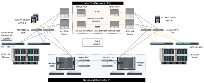
Cisco ACI Multi-Pod configuration is enabled to manage the network at both of the datacenters as a single entity such that the single cluster of APIC controllers is utilized to manage both ACI fabrics. Cisco ACI Multi-Pod allows layer-2 extensions across both sites and allows layer-3 connectivity out of the ACI fabric utilizing the local gateways at each datacenter for optimal routing configuration. At the virtualization layer, VMware vSphere High Availability (HA) is enabled for all the ESXi hosts and a single vCenter instance manages this HA cluster and the VMware vSphere Metro Storage Cluster (vMSC) guidelines are implemented. Two NetApp AFF A700 systems configured for MetroCluster IP provide a seamless, fully replicated storage solution for workloads deployed on these ESXi hosts in either datacenter. The validated solution achieves the following core design goals:
· Campus wide and metro wide protection and provide WAN based disaster recovery
· Design supporting active/active deployment use case
· Common management layer across multiple (two) datacenters for deterministic deployment
· Consistent policy and seamless workload migration across the sites
· IP based storage access and synchronous replication
The FlexPod Datacenter with Cisco ACI Multi-Pod, NetApp MetroCluster IP, and VMware vSphere 6.7 solution is comprised of the following four design areas:
· FlexPod Datacenter with ACI
· Cisco ACI Multi-Pod
· Inter Pod Network (IPN)
· NetApp MetroCluster IP
The technologies and solutions of each of these areas is described in the following sections.
FlexPod Datacenter with ACI
FlexPod is a datacenter architecture built using the following infrastructure components for compute, network, and storage:
· Cisco Unified Computing System (Cisco UCS)
· Cisco Nexus and Cisco MDS Switches
· NetApp Storage Systems (FAS, AFF, etc.)
These components are connected and configured according to the best practices of both Cisco and NetApp and provide an ideal platform for running a variety of workloads with confidence. The reference architecture described in this document leverages the components detailed in the FlexPod Datacenter with VMware 6.5 Update1 and Cisco ACI 3.1 Design Guide.
![]() The FlexPod with ACI design utilized in this solution was built using the core design principles and configurations outlined in the FlexPod Datacenter with VMware 6.5 Update1 and Cisco ACI 3.1 Design Guide. However, some software and hardware upgrades such as the new vSphere version 6.7, ACI version 3.2, and NetApp data ONTAP 9.4 running on NetApp AFF A700 controllers are introduced in this solution.
The FlexPod with ACI design utilized in this solution was built using the core design principles and configurations outlined in the FlexPod Datacenter with VMware 6.5 Update1 and Cisco ACI 3.1 Design Guide. However, some software and hardware upgrades such as the new vSphere version 6.7, ACI version 3.2, and NetApp data ONTAP 9.4 running on NetApp AFF A700 controllers are introduced in this solution.
Figure 2 FlexPod DC with Cisco ACI Components
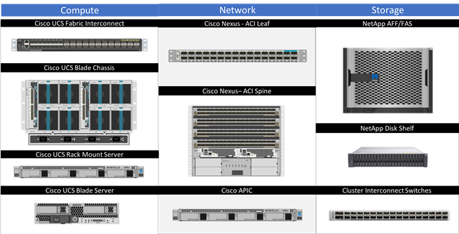
One of the key benefits of FlexPod is the ability to maintain consistency at both scale-up and scale-out models. FlexPod can scale-up for greater performance and capacity by the addition of compute, network, or storage resources as needed. FlexPod can also scale-out where you need multiple consistent deployments like rolling out additional FlexPod modules. Each of the component families shown in Figure 2, Cisco Unified Computing System, Cisco Nexus Switches, and NetApp storage arrays offer platform and resource options to scale the infrastructure up or down while supporting the same features and functionality.
For technical and design overview of the compute, network, storage and management components of the FlexPod with ACI solution, see:
Cisco ACI Multi-Pod
The ACI Multi-Pod solution allows interconnecting and centrally managing ACI fabrics deployed in separate, geographically dispersed datacenters. In an ACI Multi-Pod solution, a single APIC cluster is deployed to manage all of the different ACI fabrics that are interconnected using an Inter-Pod Network (IPN) as shown in Figure 3. The separate ACI fabrics are named “Pods” and each of the pods looks like a regular two-tier spine-leaf fabric. A single APIC cluster can manage up to 12 Pods (at this time) and various controller nodes that make up the cluster, can be deployed across these pods for resiliency. The deployment of Multi-Pod, as shown, meets the requirement of building Active/Active Data Centers, where different application components can be deployed across Pods.
Figure 3 Cisco ACI Multi-Pod Design
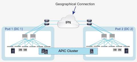
Deploying a single APIC cluster simplifies the management and operational aspects of the solution as all the interconnected Pods essentially function as a single ACI fabric. The ACI configuration (VRFs, Bridge Domains, EPGs, etc.) and policies are made available across all the pods, providing a high degree of freedom for connecting endpoints to the fabric. Different workloads such as web and application servers can be connected to or moved across different datacenters without having to re-provision or reconfigure policies in various locations.
Multi-Pod configuration offers failure domain isolation across pods through separation of the fabric control plane protocols. Different instances of IS-IS, COOP and MP-BGP protocols run inside each pod therefore faults and issues from one pod are contained within the pod and not spread across the entire Multi-Pod fabric.
The Cisco ACI Multi-Pod solution can be deployed in the same physical datacenter to accommodate specific physical requirements such as existing cabling, power limitation in racks or space constraints. However, the most common use case for ACI Multi-Pod deployment is captured in Figure 3 where the pods represent geographically dispersed datacenters. In this model, the solution meets the requirement of building Active/Active datacenters where different application components can be freely deployed across geographically separated pods to safeguard against single site failures. These different datacenter networks are usually deployed in relative proximity (metro area) and are interconnected leveraging point-to-point links (dark fiber connections or DWDM circuits).
In the FlexPod Datacenter with Cisco ACI Multi-Pod and NetApp MetroCluster IP solution, a three node APIC cluster manages an ACI fabric comprising of two Cisco Nexus 9504 spine switches and four Cisco Nexus 9300 based leaf switches at each datacenter. While a single pair of ACI leaf switches is sufficient for supporting the FlexPod design, an additional pair of Nexus switches provides dedicated border leaf functionality to showcase the design flexibility and to enable future scalability. The Cisco Nexus 9504 with N9K-X9732C-EX line cards are deployed as spine switches and are dual-connected to Cisco Nexus 7004 switches acting as Inter-Pod Network devices as shown in Figure 1.
Inter-Pod Network
Different pods (datacenters) in a Multi-Pod environment are interconnected using an Inter-Pod Network (IPN). Each pod connects to the IPN through the spine nodes. The IPN is provides basic Layer 3 connectivity allowing establishment of spine to spine and leaf to leaf VXLAN tunnels across the datacenters. The IPN device can be any device that can support:
· A routing protocol such as OSPF
· PIM bi-dir configuration for broadcast, unknown unicast and multicast (BUM) traffic
· DHCP relay functionality to allow auto-provisioning of ACI devices across the pods
· Increased MTU (9150 bytes) for handling VxLAN overhead across the pods
For more information about Multi-Pod design and setup, see: https://www.cisco.com/c/en/us/solutions/collateral/data-center-virtualization/application-centric-infrastructure/white-paper-c11-737855.html
In the FlexPod Datacenter with Cisco ACI Multi-Pod, NetApp MetroCluster IP and VMware vSphere 6.7 solution, dedicated Virtual Device Contexts in each Nexus 7004 are configured to act as IPN devices. The pair of Nexus 7004 in each datacenter was connected together using 75KM long fiber to emulate geographically dispersed Pods.
![]() To connect a 40G port on the spine to a 10G ports on the Nexus 7004, CVR-QSFP-SFP10G was installed in the Nexus 9504 40G ports.
To connect a 40G port on the spine to a 10G ports on the Nexus 7004, CVR-QSFP-SFP10G was installed in the Nexus 9504 40G ports.
VMware vSphere Metro Storage Cluster (vMSC)
A VMware vSphere Metro Storage Cluster configuration is a specific storage configuration that combines replication with array-based clustering. These solutions are typically deployed in environments where the distance between data centers is limited, often metropolitan or campus environments. A VMware vMSC configuration is a VMware vSphere certified solution that combines synchronous replication with array-based clustering. These solutions are implemented with the goal of reaping the same benefits that high-availability clusters provide to a local site, but in a geographically dispersed model with two data centers in different locations. The architecture is built on the idea of extending what is defined as local in terms of network and storage and enabling these subsystems to span geographies, presenting a single and common base infrastructure set of resources to the vSphere cluster at both sites. The primary benefit of a stretched cluster model is that it enables fully active and workload-balanced data centers to be used to their full potential and it allows for an extremely fast recovery in the event of a host or even full site failure.
Stretched cluster solutions offer the following benefits:
· Workload mobility
· Cross-site automated load balancing
· Enhanced downtime avoidance
· Disaster avoidance
· Fast recovery
For detailed information about VMware vMSC deployment requirements and best practices, see: https://storagehub.vmware.com/t/vsphere-storage/vmware-vsphere-r-metro-storage-cluster-recommended-practices/
NetApp MetroCluster
Several enterprises worldwide have implemented NetApp MetroCluster to protect their mission-critical applications. MetroCluster provides high availability, zero data loss, and non-disruptive operations in active/ active datacenters. In today’s world of infrastructure consolidation in the datacenter, it is critical that the infrastructure for key applications maintains the availability of data and services through any outages. It is for this reason that this solution is built on storage protected by MetroCluster.
MetroCluster can be implemented in various sizes for different customer needs. Various configurations are available, from configurations that consist of two NetApp controllers to configurations that include eight NetApp controllers.
Configurations with two controllers use the remote site for HA and DR functionalities. These configurations use less hardware and are more suited for smaller workloads or shorter campus distances. Configurations with four or more controllers are better suited for large enterprises because of the wide range of distances supported and the capability to execute HA operations locally instead of being required to fail over to the other site.
In the past, NetApp MetroCluster required a Fibre Channel (FC) connection, however, starting with ONTAP 9.3, MetroCluster can be configured to use an IP connection between the sites. This provides a simpler solution and requires lesser dedicated hardware when compared to the previous MetroCluster over FC implementation.
For more information about MetroCluster IP and its deployment, see:
· MetroCluster IP Installation and Configuration Guide
The FlexPod Datacenter with Cisco ACI Multi-Pod, NetApp MetroCluster IP, and VMware vSphere 6.7 solution targets interconnecting and centrally managing two geographically dispersed datacenters to provide infrastructure high availability and disaster recovery in a metropolitan area. The two datacenters are connected using a multicast enabled IP based network provisioned on Nexus 7004 switches. This CVD incorporates a few new technologies to enhance and simplify the multi-datacenter design compared to the previous generation of the FlexPod Datacenter with NetApp MetroCluster:
· Cisco Overlay Transport Virtualization (OTV) is no longer required to provide layer-2 VLAN extension across the two sites since the layer-2 extension capability is inherently provided by the Cisco ACI Multi-Pod configuration.
· NetApp MetroCluster IP design removes the requirement of deploying and maintaining Cisco MDS based SAN for setting up the MetroCluster environment. Utilizing IP-based transport, the new MetroCluster design now uses Cisco Nexus 3000 switches to achieve similar functionality.
· With the introduction of Cisco ACI to the architecture, the network programmability has become a centerpiece of the solution design.
The FlexPod Datacenter solution is flexible in nature and this particular design is no different. However, since FlexPod Datacenter with NetApp MetroCluster IP is a multi-datacenter solution where network, compute and storage extend across sites connected over WAN, some bandwidth and distance considerations are outlined in the Requirements section below.
Requirements
The FlexPod Datacenter with Cisco ACI Multi-Pod and NetApp MetroCluster IP reference architecture extends great flexibility to the customers for customizing the solution suitable for their individual organizational needs.
The following design considerations should be observed when setting up various parts of your solution:
· When deploying a Cisco ACI Multi-Pod environment, the ACI configuration needs to be completed in the following order:
- Cisco ACI configuration for the first site is completed first and the leaf and spine switched are discovered and added to an ACI Pod. Currently, the Pod ID value should be between 1 and 12. This step can be skipped if the customer already has deployed a single site Cisco ACI based FlexPod configuration (brown-field deployment).
- Cisco Multi-Pod configuration is then invoked to configure the connectivity from the spine switches at the first site to Nexus 7004 Inter Pod Network (IPN) devices. The IPN devices at both sites must be pre-configured with appropriate IPN device configuration.
- The spine switches at the second site are discovered by that APIC and added to the ACI fabric as a second Pod.
- Spine switches at the second site are configured for connectivity to the IPN devices.
- The leaf switches along with any additional APIC controllers from site 2 are then discovered and added to a second ACI Pod.
- Once the above steps are completed, Cisco APIC (cluster) can now be used to configure the second site for FlexPod related configuration and device mappings.
· An IPN device must be capable of supporting following features:
- A routing protocol such as OSPF
- PIM bi-dir configuration for broadcast, unknown unicast and multicast (BUM) traffic
- DHCP relay functionality to allow auto-provisioning of ACI devices across the pods
- Increased MTU (9150 bytes) for handling VxLAN overhead across the pods
· The maximum round trip latency for Ethernet Networks between two sites must be less than 10 ms.
· The MetroCluster IP back end must use a dedicated physical link connecting the switches at the respective sites with stretched layer 2 connectivity.
· NetApp recommends using a dual 40Gb link per switch for peak performance on an AFF A700 MetroCluster IP configuration. If the workload does not require such a high throughput, 10Gb links can be used.
· The distance between the two sites should be no more than 100km (60 miles).
· Identical storage configuration on both sites is required. Storage controller model, disk-shelf model and quantity as well as capacity and number of drives deployed should be the same.
· Cisco UCS server processors should ideally be same across both the sites to be able to support vMotion across sites. However, customers can choose to configure vSphere Enhanced vMotion compatibility (EVC) for brownfield deployments.
· Maximum number of hosts in a vSphere HA cluster should not exceed 32.
![]() For more information about deploying VMware with NetApp MetroCluster, see: https://kb.vmware.com/s/article/2031038.
For more information about deploying VMware with NetApp MetroCluster, see: https://kb.vmware.com/s/article/2031038.
Physical Topology
The high level physical topology for the FlexPod Datacenter with Cisco ACI Multi-Pod and NetApp MetroCluster IP is shown in Figure 4.
Figure 4 High-level Physical Topology
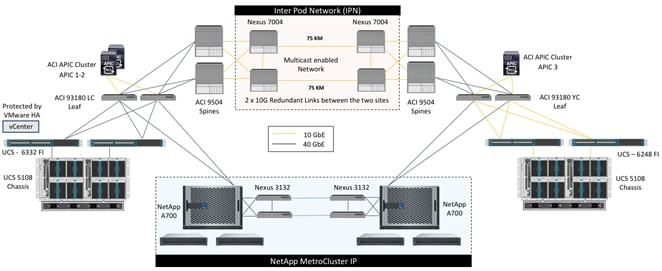
To validate the solution, the two FlexPod with ACI sites use the hardware components listed below. While the two sites should ideally be identical, the validation was performed in a mixed 40GbE and 10GbE environment to showcase the flexibility and breadth of the supported solution. Including both Gen2 Cisco UCS 6248 and Gen 3 Cisco UCS 6332 Fabric Interconnects along with the appropriate Nexus 9300 leaf devices allows customers to realize solution support for mismatched site components.
Inter Pod Network (IPN)
· 2 x Cisco Nexus 7004 with N7K-SUP2E supervisor and N7K-M224XP-23L line-card at each site
Site 1 (40 GbE connectivity)
· 2 x Cisco Nexus 93180LC-EX leaf switches
· 2 x Cisco Nexus 9504 Spine switches with N9K-X9732C-EX line-card
· 2 x Cisco UCS 6332-16UP Fabric Interconnects and a Cisco UCS 5108 Chassis with B200 M5 servers
· NetApp AFF A700 storage controller and 2 x NetApp DS224-12 shelves
Site 2: (10 GbE connectivity)
· Cisco Nexus 93180YC-EX leaf switches
· 2 x Cisco Nexus 9504 Spine switches with N9K-X9732C-EX line-card
· 2 x Cisco UCS 6248 Fabric Interconnects and a Cisco UCS 5108 Chassis with B200 M5 servers
· NetApp AFF A700 storage controller and 2 x NetApp DS224-12 shelves
MetroCluster IP Connectivity
· 2 x Cisco Nexus 3132Q-V switches at each site
Optional Devices*
· 2 x Cisco Nexus 9372PX border leaf switches
![]() * While a single pair of ACI leaf switches is sufficient to support the FlexPod design, an additional pair of Cisco Nexus switches provides dedicated border leaf functionality to showcase the design flexibility and to support future scalability.
* While a single pair of ACI leaf switches is sufficient to support the FlexPod design, an additional pair of Cisco Nexus switches provides dedicated border leaf functionality to showcase the design flexibility and to support future scalability.
The following sections describe the connectivity details and configuration requirements of various hardware devices and components.
Inter Pod Network (IPN) Connectivity
The Inter Pod Network (IPN) consists of four Nexus 7004 switches connected as shown in Figure 5:
Figure 5 Inter Pod Network Physical Design
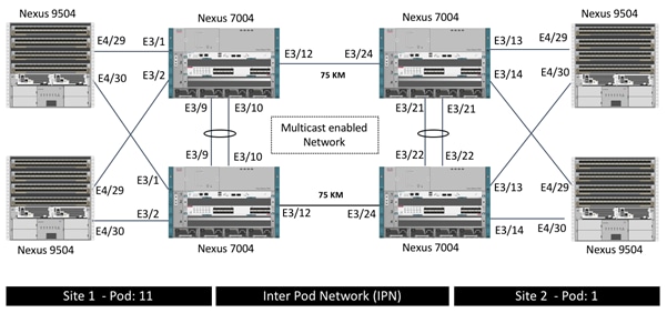
At each site, both the Cisco Nexus 9504 Spine switches are connected to both the Cisco Nexus 7004 devices for high availability as shown in Figure 5 using 10GbE connections. Cisco Nexus 9504 Spine switches with N9K-X9732C-EX line-card only support 40G ports. To connect the 40G port on Cisco Nexus 9504 to a 10G port on the Cisco Nexus 7004, the CVR-QSFP-SFP10G adapter is utilized on the spine switches. The two long distance connections between the Cisco Nexus 7004 devices are achieved by using SFP-10G-ZR optics connected to 75KM long fiber. As shown in Figure 5, all the network connectivity is fully redundant and failure of one or in some cases more than one link (or device) will keep the connectivity intact.
MetroCluster IP Connectivity
The physical connectivity for MetroCluster IP nodes is shown in Figure 6.
Figure 6 MetroCluster IP Physical Connectivity

Intercluster Switch
The intercluster switch, Cisco Nexus 3132Q-V, is used for the cluster HA interconnect, MetroCluster IP iSCSI traffic, and IP HA and DR replication across the IP fabric. This switch is dedicated for back-end connectivity only and can be configured quickly with RCF files, downloadable from the NetApp Support site.
Broadcast Domain
The MetroCluster IP solution includes several types of traffic within each site and between sites. It is essential to keep these different traffics isolated from each other to avoid unnecessary packet flooding and to streamline allocation of network resources. It is a best practice to separate the MetroCluster ports from the non-MetroCluster ports, which will prevent MetroCluster LIFs from failing over to non-MetroCluster ports and vice-versa. To implement this, separate broadcast domains are created to house these ports and the upstream Ethernet switches to which these ports are connected, will have VLANs configured to achieve the separation.
Logical Interfaces
Each node in a MetroCluster configuration has two ports dedicated for iWARP/iSCSI DR TCP and iWARP HA TCP connections. Two LIFs are created on each node using those two ports, and the network/IP used is checked by “vifmgr” to ensure that there are no conflicts. Subsequently, these LIFs are kept in a separate table by “vifmgr” as an exclusion list so that users do not configure the same IPs on SVMs or other LIFs. Each LIF represents both an iSCSI connection and an iWARP TCP connection and contains the repl-mcc-storage and repl-mcc-nvlog service bits. Two IP subnets are used to assign IP addresses for these LIFs and each node should be assigned two IPs, one from each subnet. These IP addresses once assigned, cannot be changed and therefore it is recommended to plan the subnet selection and subnet size carefully considering future growth.
Segregation using VLANs
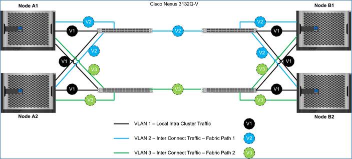
Figure 7 illustrates the VLAN layout in a four-node MetroCluster IP solution. Intercluster switches are used to segregate traffic with the help of VLANs. The default VLAN 1 is used for all intercluster HA replication as a standard. For MetroCluster IP, an additional VLAN is required per fabric. Therefore, Intercluster Switch A has VLAN 1 and an additional VLAN Fabric-A; Intercluster Switch B has VLAN 1 and an additional VLAN Fabric-B. The additional VLANs are configured on the switches using the RCF files and should not be changed unless the customer has strict requirements for specific VLAN schemas in their infrastructure. The VLANs provisioned in the RFC files have no effect on the existing VLANs as they are isolated from the other networks in the infrastructure.
Figure 7 MetroCluster VLAN Configuration
Ethernet Adapter for the IP Fabric
IP interfaces are created on each node in the MetroCluster IP fabric and these logical interfaces are hosted on a 40/100 Gbps Ethernet adapter. These adapters need to be mounted in a specific slot depending on the controller model. For an AFF A700, the X91146A-C 40/100-Gbps adapter needs to be mounted in Slot #5. To identify the slot required, see the MetroCluster IP Installation and Configuration Guide.
Site 1 Connectivity
FlexPod configuration for Site 1 supports 40GbE end to end connectivity as shown in Figure 8.
Figure 8 Site 1 Physical Connectivity
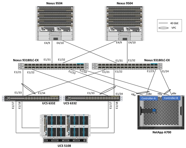
Cisco Nexus 93180LC-EX leaf switches act as the ACI leaf devices and terminate 40GbE connections from both Cisco UCS 6332 Fabric Interconnects (FI) as well as NetApp AFF A700 controllers. Each Cisco UCS 6332 FI is connected to the Cisco UCS 2304 Fabric Extender using 2 x 40G connections. All the connections from the UCS FIs and NetApp AFF A700 to the ACI leaf switches are configured as Virtual Port Channels (VPC) to aggregate the two physical 40G connections into a single logical 80G connection. Depending on customer throughput requirements, additional physical links can be easily added to the above setup.
Site 2 Connectivity
FlexPod configuration for Site 2 supports a mixed 10GbE and 40GbE connectivity as shown in Figure 9.
Figure 9 Site 2 Physical Connectivity
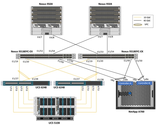
Cisco Nexus 93180YC-EX leaf switches act as the ACI leaf devices and terminate 10GbE connections from both Cisco UCS 6248 Fabric Interconnects (FI) as well as 40GbE connections from NetApp AFF A700 controllers. Each Cisco UCS 6248 FI is connected to the Cisco UCS 2308 Fabric Extender using 4 x 10G connections. The 6 40G ports on Cisco Nexus 93180YC-EX switch are configured as uplink ports by default however up to four of these six ports can now be converted to downlink ports for 40G compute or storage connectivity. To connect the NetApp AFF A700 to the leaf switches using 40GbE connections, ports E1/49-E1/50 were converted to downlink ports. All the connections from the UCS FIs and NetApp AFF A700 to the ACI leaf switches are configured as Virtual Port Channels (VPC) to aggregate the multiple physical 10G and 40G connections into a single logical connection. Depending on customer throughput requirements, additional physical links can be easily added to the above setup.
Logical Topology
The previous section of this document covered physical connectivity details of the solution. At a high-level, there are two unique geographically dispersed datacenters that are connected using Cisco ACI Multi-Pod technology at the network layer and NetApp MetroCluster IP technology at the storage layer. Using the in-built VLAN extension mechanism of Cisco ACI Multi-Pod, the compute infrastructure at both datacenters is connected such that hosts and storage at one site can reach the hosts and storage at the other site without requiring any layer-3 routing configuration. Figure 10 showcases the logical design of the solution where various traffic segments, including iSCSI and NFS storage traffic, can seamlessly span the two datacenters because of layer-2 extended design. As seen in Figure 9, the hosts in each physical datacenter can access both local and remote NetApp storage systems without differentiating local system from the remote system thereby utilizing data paths within and across the datacenters. The datastore and LUN access throughput and latency however can be quite different depending on the relative location of the ESXi host and the storage controller. By using host affinity rules as well as by preferring local datastores on each site, the latency and throughput related limitations can be easily avoided.
Figure 10 Logical Setup for the Solution

To enable a single logical virtualized architecture across two physical datacenters, each ESXi host is configured with the same iSCSI-A, iSCSI-B and NFS VLANs and subnets. NetApp controllers at both datacenters are also configured with iSCSI and NFS LIFs using the same VLANs and IP subnets. The ACI Multi-Pod configuration then allows the VMkernel interfaces on the compute nodes in each datacenter to communicate with the storage LIFs as if both the interfaces are on the same LAN segment. Finally, adding the ESXi hosts across the two sites to the same VMware High Availability (HA) Cluster enables HA features across the two sites.
ACI Multi-Pod Design
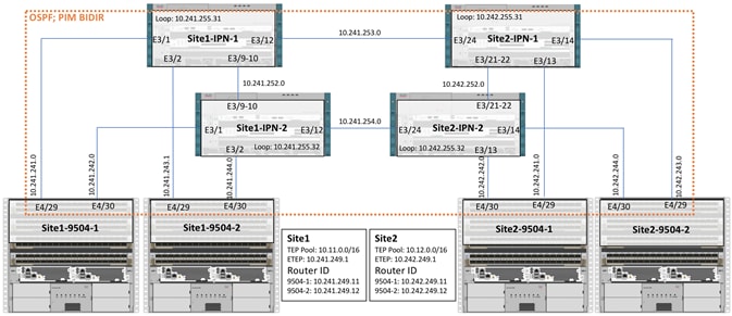
The ACI Multi-Pod design used in this CVD has several components which are highlighted in Figure 11. The details of these components and their usage is described below.
IPN Configuration Requirements
The Inter-Pod Network consists of two Nexus 7004 switches in each datacenter connected using a 10Gbps 75 km long fiber. The dual link design provides high availability in case of a link failure. Each spine is connected to each of the Nexus 7004s using a 10Gbps connection for a fully redundant setup.
Each Nexus 7004 is configured with the following features to support the Multi-Pod network.
PIM Bidir Configuration
In addition to unicast communication, layer-2 multi-destination flows belonging to bridge domains that are extended across the ACI pods must also be supported. This type of traffic is usually referred to as Broadcast, Unknown Unicast and Multicast (BUM) traffic and it is exchanged by leveraging VXLAN data plane encapsulation between leaf nodes. Inside a Pod (or ACI fabric), BUM traffic is encapsulated into a VXLAN multicast frame and it is always transmitted to all the local leaf nodes. In order to flood the BUM traffic across Pods, the same multicast used inside the Pod must also be extended through the IPN network. PIM bidir enables this functionality on the IPN devices.
OSPF Configuration
OSPF is enabled on Spine switches and IPN devices to exchange routing information between the Spine switches and IPN devices.
DHCP Relay Configuration
In order to support auto-provisioning of configuration for all the ACI devices across multiple ACI pods, the IPN devices connected to the spines must be able to relay DHCP requests generated from ACI devices in remote Pods toward the APIC node(s) active in the first Pod.
Interface VLAN Encapsulation
The IPN device interfaces connecting to the ACI Spines are configured as sub-interfaces with VLAN encapsulation value set to 4.
MTU Configuration
The IPN devices are configured for maximum supported MTU value of 9216 to handle the VxLAN overhead.
TEP Pools and Interfaces
In Cisco ACI Multi-Pod setup, unique Tunnel Endpoint (TEP) Pools are defined on each site. In this CVD, these pools are 10.11.0.0/16 and 10.12.0.0/16 for the two datacenters.
External TEP
The pod connection profile uses a VXLAN TEP (VTEP) address called the External TEP (ETEP) as the anycast shared address across all spine switches in a pod. This IP address should not be part of the TEP pool assigned to each pod and is therefore selected outside the two networks listed above. The IP addresses used in the two datacenters are 10.241.249.1 and 10.242.249.1.
APIC Controller Considerations
The ACI Multi-Pod fabric brings interesting considerations for the deployment of the APIC controller cluster managing the solution. To increase the scalability and resiliency of the design, APIC supports data sharding for data stored in the APIC. The basic idea behind sharding is that the data repository is split into several database units, known as ‘shards’ and the shard is then replicated three times, with each copy assigned to a specific APIC appliance. In a three node APIC cluster, one replica of each shard exists on every node. In this scenario, if two of the three nodes become unavailable as shown in Figure 12, the shards in third node become read-only because of lack of quorum and stay in read-only mode until the other nodes become accessible again.
Figure 12 APIC Nodes and Data Sharding
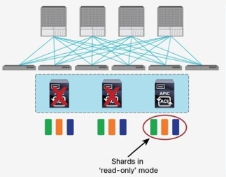
In Figure 4, the three APIC nodes are distributed across the two datacenters. In case of a split-brain scenario where two datacenters cannot communicate to each other over the IPN, this implies that the shards on the APIC nodes in Site1 would remain in full ‘read-write’ mode, allowing a user connected there to make configuration changes however the shards in Site2 will move to a ‘read-only’ mode. Once the connectivity issues are resolved and the two Pods regain full connectivity, the APIC cluster would come back together and any change made to the shards in majority mode would be applied also to the rejoining APIC nodes.
To mitigate this scenario, customers can deploy a 3 node APIC cluster with two nodes in Site1 and one node in Site2 and then add a fourth backup APIC node in Site2 to handle the full site failure scenario. The backup APIC server however should only be brought into action if a long-term connectivity outage or datacenter maintenance is expected. For typical short-term outages, three node cluster should suffice in most scenarios.
For detailed information about APIC cluster and sizing recommendations, consult the ACI Multi-Pod White Paper.
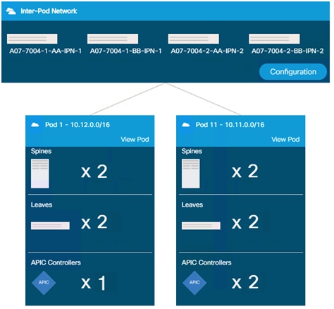
After the Cisco ACI Multi-Pod configuration is complete, customers can observe and configure various aspects of the Multi-Pod configuration in Cisco APIC as shown in Figure 13. The Topology overview shown in Figure 13 highlights various configuration aspects of the design including number of Pods as well as Pod components such as spine switches, leaf switches and APICs.
Figure 13 APIC Multi-Pod Configuration
Datacenter Architecture
Both datacenters in the solution align with the FlexPod Datacenter converged infrastructure configurations and best practices. The system includes hardware and software compatibility support between all components and aligns to the configuration best practices for each of these components.
All the core hardware components and software releases are listed and supported in the Cisco UCS Hardware and Software Compatibility page and the NetApp Interoperability Matrix Tool (Login required).
Each system supports high availability at network, compute and storage layers such that no single point of failure exists in the design. The system utilizes 10 and 40Gbps Ethernet jumbo-frame based connectivity combined with port aggregation technologies such as virtual port-channels (VPC) for non-blocking LAN traffic forwarding as shown in Figure 8 and Figure 9.
Some of the key features of the datacenters are highlighted below:
· The system is able to tolerate the failure of compute, network, or storage components without significant loss of functionality or connectivity
· The system is built with a modular approach thereby allowing customers to easily add more network (LAN or SAN) bandwidth, compute power or storage capacity as needed
· The system supports stateless compute design thereby reducing time and effort required to replace or add new compute nodes
· The system provides network automation and orchestration capabilities to the network administrators using Cisco APIC GUI, CLI and restful API
· The systems allow the compute administrators to instantiate and control application Virtual Machines (VMs) from VMware vCenter
· The system provides storage administrators a single point of control to easily provision and manage the storage using NetApp System Manager
· The solution supports live VM migration between various compute nodes and protects the VM by utilizing VMware HA and DRS functionality
· The system can be easily integrated with optional Cisco (and third party) orchestration and management application such as Cisco UCS Central and Cisco UCS Director
· The system showcases layer-3 connectivity to the existing enterprise network
The FlexPod Datacenter with Cisco ACI Multi-Pod, NetApp MetroCluster IP and VMware vSphere 6.7 solution not only supports all these single site benefits, it expands these benefits by applying them to multiple sites for enhances high availability and disaster avoidance.
For detailed information about the FlexPod DC with ACI design components, refer to the FlexPod Datacenter with VMware 6.5 Update1 and Cisco ACI 3.1 Design Guide.
Compute Infrastructure Design
The Cisco UCS configuration on both datacenters is identical and follows the configuration guidelines of the Cisco FlexPod datacenter for ACI. Figure 14 illustrates the traffic segments (VLANs) that are extended to both the Cisco UCS domains:
Figure 14 Cisco UCS Connectivity in Both Datacenters
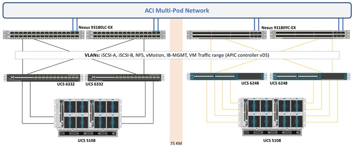
Cisco UCS domains in each datacenter connect to the Cisco ACI leaf switches using Virtual Port Channels (VPC). Each VPC link allows the following VLANs:
· iSCSI-A (3010)
· iSCSI-B (3020)
· NFS (3050)
· vMotion (3000)
· IB-MGMT (213)
· Native (2)
· Traffic VLANs (1101-1150)
To enable these VLANs for UCS domains in both datacenters, a single VLAN pool, layer-2 domain, and Attached Entity Profile (AEP) are defined in Cisco APIC as shown in Figure 15.
Figure 15 Cisco ACI Configuration for Cisco UCS Connectivity

Using ACI’s modular network definitions, any changes to the connectivity across the sites only need to be made once and propagated to both the UCS domains. The VM traffic VLANs used in the design (1101-1150) are defined in a dynamic VLAN pool, FPV-VC-VDS and are used by the Virtual Machine Management (VMM) domain when defining new end point groups.
Storage Infrastructure Design
NetApp AFF A700 configuration on both the datacenters is also identical and follows the configuration guidelines of Cisco FlexPod datacenter for ACI. Figure 16 outlines the VLANs that are extended to both the NetApp AFF A700 storage systems.
Figure 16 Storage Connectivity in Both Datacenters
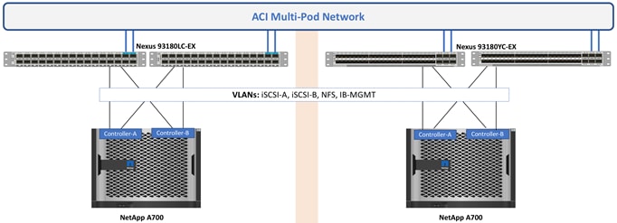
NetApp AFF A700 system in each datacenter connect to the Cisco ACI leaf switches using Virtual Port Channels (VPC). Each VPC link allows following VLANs:
· iSCSI-A (3010)
· iSCSI-B (3020)
· NFS (3050)
· IB-MGMT (213)
· Cluster VLAN (113)
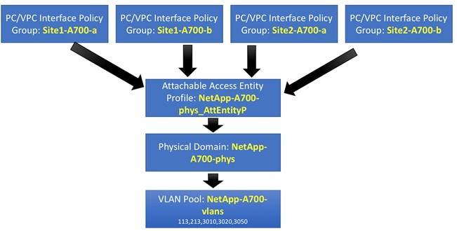
To enable these VLANs for NetApp systems in both datacenters, a single VLAN pool, physical domain and Attached Entity Profile (AEP) is defined in Cisco APIC as shown in Figure 17.
Figure 17 Cisco ACI Configuration for NetApp Connectivity
![]() Any changes to the connectivity across the sites only need to be made once and propagated to both the NetApp systems.
Any changes to the connectivity across the sites only need to be made once and propagated to both the NetApp systems.
Foundation Tenant for FlexPod Connectivity
After the Cisco ACI Multi-Pod network is operational and the physical connectivity is laid out for Cisco UCS and NetApp AFF A700 as described in the last section, a new tenant FPV-Foundation is created to define various bridge domains (BD), application profile (AP) and end point groups (EPG). As per FlexPod datacenter with ACI design guidance, the FPV-Foundation tenant consists of single VRF since there is no overlapping IP address space requirements in this design.
![]() The FPV prefix was added to the tenant name to identify the tenant containing FlexPod for VMware configuration
The FPV prefix was added to the tenant name to identify the tenant containing FlexPod for VMware configuration
Intercluster Communication
The clusters in the MetroCluster configuration must be in a peer relationship so that they can communicate with each other and perform the data mirroring essential to MetroCluster disaster recovery. To enable this communication, a dedicated Application Profile (AP), Bridge Domain (BD) and End Point Group (EPG) is created. The relationship between various constructs is show in Figure 18.
Figure 18 Intercluster Communication
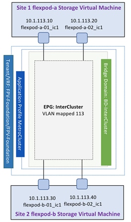
The bridge domains (BD) required for setting up intercluster communication is named BD-InterCluster. The EPG InterCluster is configured with static mappings for VLAN 113 across all NetApp AFF A700 controllers as shown in Figure 19.
Figure 19 InterCluster EPG Static Port Mappings

Compute-to-Storage Connectivity for iSCSI and NFS
To enable compute-to-storage connectivity across the two sites using iSCSI and NFS, the ACI constructs are defined as shown in Figure 20.
Figure 20 ACI Configuration for Compute-to-Storage Connectivity
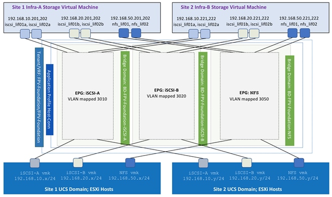
The bridge domains (BD) required for completing compute to storage connectivity are:
· BD-FPV-Foundation-iSCSI-A: BD associated with EPGs for iSCSI-A traffic
· BD-FPV-Foundation-iSCSI-B: BD associated with EPGs for iSCSI-B traffic
· BD-FPV-Foundation-NFS: BD associated with EPGs for NFS traffic
While all the EPGs in a tenant can theoretically share the same bridge domain, overlapping MAC address usage by NetApp storage controllers on the interface groups across multiple VLANs requires a unique bridge domain per LIF. As shown in Figure 20, the FPV-Foundation tenant connects to two iSCSI and one NFS LIF per controller to provide storage connectivity to the infrastructure SVM. Since these three LIFs on each storage controller share the same MAC address, a separate BD is required for each type of storage traffic.
All the storage EPGs are defined under a single Application Profile Host-Conn. In addition to the storage traffic, this application profile also hosts an EPG for vMotion connectivity between all the ESXi hosts (not shown in the Figure 20).
Each EPG shown in Figure 20 is configured with static port mapping for both Site1 and Site2 UCS domains as well as Site1 and Site2 NetApp AFF A700 storage systems. These mappings allow compute and storage systems in both datacenters to communicate with each other directly. Figure 21 shows static port mappings for the NFS EPG. Both iSCSI-A and iSCSI-B EPGs have similar mappings defined on APIC.
Figure 21 Static Port Mapping for NFS

Management Network Design
The management network in The FlexPod datacenter with Cisco ACI Multi-Pod and NetApp MetroCluster IP solution is configured according to the FlexPod datacenter with ACI guidelines and best practices. To provide ESXi hosts and VMs access to an existing management segment where core-services such as Active Directory (AD), Domain Name Services (DNS), etc. reside, the pre-defined tenant common is utilized. The policies defined in the common tenant are usable by all the tenants without any special configurations and all tenants in the ACI fabric can “consume” the contracts “provided” in the common tenant.
In the current multi-datacenter design, the management VLAN also extends across the two sites making the component management across the domains seamless. Figure 22 shows various constructs required to set up the common management segment.
Figure 22 ACI Configuration for Management Network

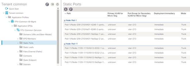
The bridge domains (BD) required for setting up management connectivity in the tenant common is named FPV-Common-IB. The EPG FPV-Common-Services is configured with static mappings for VLAN 213 across all Cisco UCS Fabric Interconnects and NetApp AFF A700 controllers as shown in Figure 23.
Figure 23 Static Port Mappings for Common Management Segment
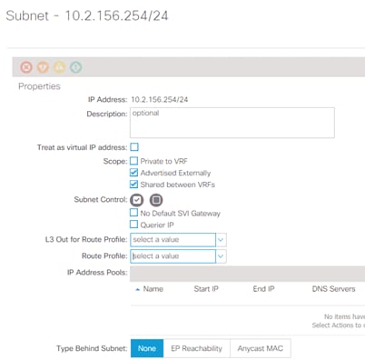
After the static port mapping configuration for the EPG FPV-Common-Services is complete, the subnet gateway is defined for the VMs that are part of the IB-MGMT EPG. The GW should be allowed to be shared between the VRFs as well should be allowed to be advertised out of the ACI fabric to enable access to management network from outside the ACI environment.
Figure 24 IB-MGMT GW Scope
The tenant VMs access the core services segment by consuming contracts from the common tenant. The EPG FPV-Common-Services provides a contract with global scope called FPV-Allow-Common-Services. The contract filters can be configured to only allow specific services related ports. Some applications such as NetApp SnapDrive® require direct connectivity from the application (SharePoint, Exchange, SQL, etc.) VMs to the management LIFs and the above configuration enables this connectivity as well.
External Network Access
In a single site FlexPod datacenter with Cisco ACI design, the connectivity between the ACI fabric and the external routed network domain is achieved with the definition of a shared L3Out connection. In order to connect the ACI fabric to existing infrastructure, the leaf nodes are connected to a pair of infrastructure routers or switches such as Cisco Nexus 7004 (in this design). The connection is defined in the tenant common and provides a contract to be consumed by all the application EPGs that require access to non-ACI networks. Tenant network routes can be shared with the Nexus 7004 switches using OSPF and external routes from the Nexus 7000s are shared with the tenant.
The FlexPod Datacenter with Cisco ACI Multi-Pod, NetApp MetroCluster IP and VMware vSphere 6.7 solution utilizes two separate geographically dispersed datacenters where each datacenter leverages its own connection to the external network domain for optimal routing as shown in Figure 25.
Figure 25 External Network Connectivity
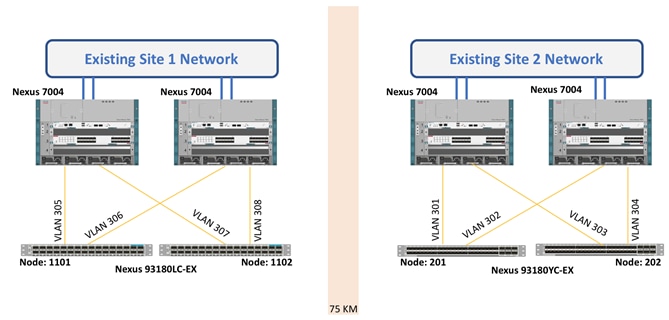
In each datacenter, the leaf switches connect to the enterprise switches (Nexus 7004) using four routed sub-interfaces. In the current design, all eight sub-interfaces (four on each site) are configured under the same shared-L3Out named N7k-SharedL3Out as shown in Figure 26.
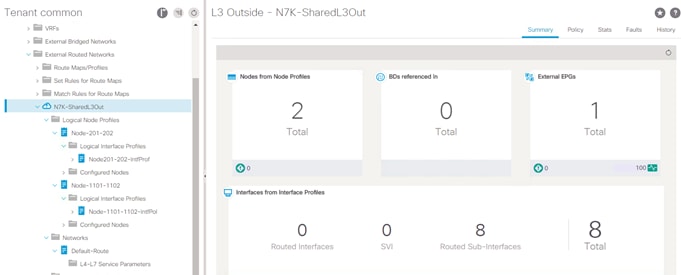
In this implementation, a default route is injected inside the Multi-Pod environment from Nexus 7004 switches in both datacenters however endpoints deployed in a given Pod always leverage the local connection to the Nexus 7004 switches for the external destinations. Cisco ACI Multi-Pod inherently configures the routing metrics correctly to achieve this functionality and no additional customer configuration is required.
Virtualization Design
Integrating Cisco ACI with VMware vCenter using the Virtual Machine Management (VMM) domain configuration allows Cisco ACI to control the virtual switches running on the ESXi hosts and to extend the fabric access policies to Virtual Machines (VM) deployed on ESXi host. The integration also automates the deployment tasks associated with connecting a distributed virtual switch to the ACI fabric. In FlexPod datacenter with Cisco ACI Multi-Pod and NetApp MetroCluster IP solution, a single vCenter is used to manage an ESXi cluster spanning both datacenters. To protect the vCenter appliance against host and site failures, the vCenter VM is deployed on the same ESXi cluster which spans the two datacenters.
The ESXi host configuration for connectivity at both datacenters follows the guidelines of FlexPod datacenter with ACI and is identical across the two sites. As covered in the compute infrastructure section, both UCS domains use the same attachable access entity (AEP). By attaching this common AEP with the VMM deployment, workloads can be deployed in either of the two datacenters without making any special configuration considerations. In the FlexPod datacenter with ACI designs, tenant applications are deployed on port-groups in the APIC-controlled distributed switch (VMware vDS) but for other infrastructure connections such as vCenter access using in-band management, vSphere vMotion and iSCSI storage access, a vSphere vSwitch per connection is used as shown in Figure 27.
Figure 27 FlexPod – Virtual Switching Design
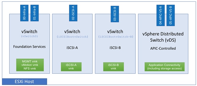
As all the other FlexPod designs, ESXi hosts are configured to boot from SAN for supporting stateless compute. Each ESXi boot LUN is created on the local NetApp controller to avoid booting across the WAN. NFS datastores are created on both the NetApp AFF A700 systems to host the VMs.
As part of initial design setup, the VM distribution across the two sites is determined and some VMs are primarily hosted in datacenter 1 while others are hosted in datacenter 2. This VM and application distribution across the two sites can be performed manually or by using an automation framework according to customer IT policies and requirements. This VM distribution is important because for optimal performance, the VMs disks should be hosted on the local NetApp AFF A700 systems to avoid additional latency and traffic across the WAN links under normal operation. VMware DRS is configured with site affinity rules to make sure the VMs adhere to customer deployment policy. Figure 28 illustrates the VMware datastore setup and site affinity concepts in detail.
Figure 28 VM Deployment Across the Two Sites
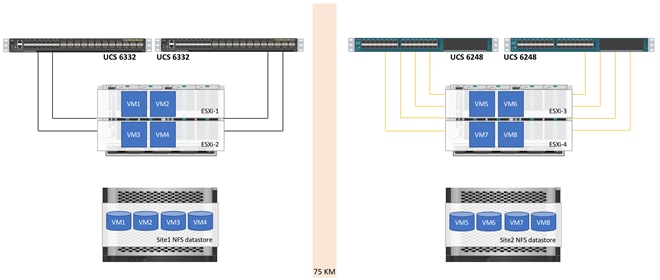
In Figure 28, VM1-VM4 have been configured with an affinity to the ESXi hosts in Site1 and the disks for these VMs is hosted on the datastore defined in Site1 NFS datastore. On the other hand, VM5 to VM8 have been configured with an affinity to ESXi hosts in Site2 and the VM disks are hosted on the datastore configured on the NetApp AFF A700 systems in datacenter 2. Under normal circumstances, the VMs access their disk locally in a site but in case of failure the traffic can potentially go across the WAN. VMware administrators and support staff can use compute or storage vMotion to improve the application response times under partial failure conditions.
MetroCluster IP Design
Recovery Point Objective and Recovery Time Objective Requirements
Businesses have a wide variety of backup options available to them. Before choosing a solution’s components, they should fully understand the needs of their infrastructure and applications in terms of recovery point objective (RPO) and recovery time objective (RTO).
RPO is the amount of time that passed since the last time a backup was taken. If an occurrence caused a loss of the infrastructure, all data written since the last backup is lost. Although some use cases can withstand the loss of data, many shared infrastructures and virtualized environments need backups to be created in minutes instead of hours. NetApp SnapMirror® and NetApp MetroCluster are two solutions for these shared infrastructure environments that can keep data loss to a minimum.
RTO is the amount of time a business is willing to wait until applications are back up and running. Many infrastructures need to be able to withstand outages with minimal downtime to enable business continuity.
FlexPod Datacenter with MetroCluster contains redundancy at every layer in the infrastructure stack so that data continues to be served even if any component fails. Additionally, the solution features a stretched cluster environment. The clusters can be separated by a distance of up to 300km. Even if there is regional power outage or a natural disaster, control can be switched to the surviving site and applications can continue to run with minimal downtime.
FlexPod solutions are available for a wide variety of RPO and RTO needs. For businesses that require continuous availability with zero data loss, FlexPod Datacenter with NetApp MetroCluster can be leveraged to create a reliable, virtualized shared infrastructure.
MetroCluster Configurations
In a Fabric MetroCluster configuration, each node in the MetroCluster is connected to local and remote disks by FC or Fibre Channel over IP (FCIP) switches and FC-to-SAS FibreBridge bridges. There are several FC switches available with a maximum distance of 300km depending on the switch model and its buffer-to-buffer credits. One advantage of the FC-based MetroCluster is its flexibility. It can be configured as a two-node, four-node, or eight-node MetroCluster and allows the controllers to connect directly to the FibreBridge bridges for campus deployments which require lesser distance between the sites.
Figure 29 Fabric MetroCluster Configuration

The MetroCluster over IP solution introduced in ONTAP 9.3, replaced the dedicated back-end FC switches with Ethernet networks; this provides a simpler deployment at reduced costs by offering the following advantages:
· Uses Ethernet ports rather than FC host adapter ports, eliminating the need for dedicated FC switches.
· Collapses the intercluster switches for both local and remote replication, eliminating the need for dedicated FC switches. Back-end replication uses dedicated Ethernet ISLs connecting to the same switch.
· Eliminates the need for SAS bridges.
· Replicates NVRAM with iWARP by using the same back-end Ethernet ports.
· Accesses remote disks using iSCSI protocol with the remote DR node acting as the iSCSI target, supporting flash platforms with integrated storage.
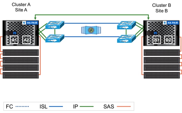
MetroCluster IP provides the same RPO and RTO value to customers as Fabric MetroCluster but mirrors the data between the sites in a different manner. The controllers use the iWARP protocol to mirror the NVRAM with minimal latency, as opposed to FCVI in an FC configuration. Because the controllers are not physically connected to the disks on the remote site, each node acts as a target, allowing its DR partner to access its pool 1 disks.
For more information about MetroCluster IP and its deployment, see:
· MetroCluster IP Installation and Configuration Guide
· MetroCluster IP Solution Deployment (Only available to NetApp partners in Field Portal)
Figure 30 MetroCluster IP Configuration
MetroCluster IP Differences
Advanced Disk Partitioning
An advantage of MetroCluster IP is that disks are no longer accessed through the FibreBridge. This opens the possibility for Advanced Disk Partitioning (also known as root-data-data disk partitioning) in ONTAP. This feature was introduced in ONTAP 9 and serves two benefits. One benefit is that it conserves space by eliminating the need for three disks to be used (or six in the case of a mirrored aggregate). Instead, a root partition is created on each node in the cluster. In this design, the space for the root aggregate takes up the minimum needed disk space of 1.4TB. Without ADP, the dedicated raw disk space required for the root aggregate is over 5TB. ADP, therefore, enables significant savings. The second benefit of ADP is that each node in the HA pair owns a partition on each disk. This provides a performance improvement by taking advantage of the high IOPS for an individual SSD.
Distance Limitation
Although an IP-based solution could theoretically be implemented for a longer distance, the maximum supported distance between the sites in ONTAP 9.4 for the MetroCluster IP solution is 100km. This is comparable to a FC-based MetroCluster, which supports up to 300km between the two sites.
Failure Scenarios
Although MetroCluster IP supports most failure scenarios as fabric MetroCluster does, some of the workflows are different and the automatic unplanned switchover (AUSO) is not supported in a MetroCluster IP configuration.
AUSO mimics the HA failover of in a regular two-node cluster and allows a cluster to automatically execute the switchover if the nodes on the other site have an issue. AUSO requires accesses to the remote site’s mailbox disks even if the controllers are not online. Because MetroCluster IP is configured to allow a node to access the remote disks through its DR partner, AUSO is not possible in the MetroCluster IP configuration.
The final major difference in the failure scenarios between Fabric MetroCluster and MetroCluster IP is the healing process. In a Fabric MetroCluster configuration, the administrator must execute the metrocluster heal commands before booting the nodes in the disaster site. In MetroCluster IP, because access to the remote disks requires the remote nodes to be up, the nodes should be booted and then the administrator can run the metrocluster heal commands. As with Fabric MetroCluster, the administrator should run the command to heal aggregates before healing the root aggregates.
Table 1 lists the hardware and software versions used for the solution validation.
![]() It is important to note that Cisco, NetApp, and VMware have interoperability matrices that should be referenced to determine support for any specific implementation of FlexPod. Please refer to the following links for more information: Cisco UCS Hardware and Software Compatibility, NetApp Interoperability Matrix (Login required), and VMware Compatibility Guide.
It is important to note that Cisco, NetApp, and VMware have interoperability matrices that should be referenced to determine support for any specific implementation of FlexPod. Please refer to the following links for more information: Cisco UCS Hardware and Software Compatibility, NetApp Interoperability Matrix (Login required), and VMware Compatibility Guide.
Hardware and Software Revisions
Table 1 Hardware and Software Revisions
| Layer | Device | Image | Comments |
| Compute | Cisco UCS Fabric Interconnects 6300/6200 Series, Cisco UCS B-200 M5 | 3.2(3d) | Includes the Cisco UCS-IOM 2208XP, IOM-2304, Cisco UCS Manager, and Cisco UCS VIC 1340 |
| Network | Cisco Nexus 9000 Switches | 13.2(2l) | iNXOS |
| Cisco APIC | 3.2(2l) | ACI release | |
|
| Nexus 7004 | 6.2(20) | Can be any NxOS release |
| Storage | NetApp AFF A700 | 9.4 | Software version |
| Cisco Nexus 3132Q-V | 7.0(3)I4(1) | NetApp recommended | |
| Software | VMware vSphere ESXi | 6.7 | Software version |
| VMware vCenter | 6.7 | Software version |
FlexPod Datacenter with Cisco ACI Multi-Pod, NetApp MetroCluster IP and VMware vSphere 6.7 solution is validated for successful infrastructure configuration and availability across the two geographically dispersed datacenters by validating a wide variety of test cases and by simulating partial and complete failure scenarios. The types of tests executed on the system are listed below.
Compute to Storage Connectivity
· Validate SAN boot configuration and vSphere Installation for iSCSI associated boot LUN
· Verify SAN access and boot with primary path to local storage array unavailable
· Verify single storage controller connectivity failure in a DC
· Verify complete storage system isolation in a DC
· Verify single Host failure in a DC
· Verify compute isolation in a DC (all hosts failed)
Multi-Pod Validation
· Verify loss of a single Leaf Switch (one after another)
· Verify loss of a single Spine (one after another)
· Verify loss of an IPN device (one after another)
· Verify loss of a single path between the IPN devices (one after another)
MetroCluster IP Validation
· Path failure between a pair of Nexus 3Ks
· Single Nexus 3K device failure
· Failure of all links between the Nexus 3Ks
Datacenter Validation
· Storage partition – Link between the two DCs goes down making two storage systems isolated
· Datacenter Isolation and recovery for compute and storage
· Datacenter maintenance use case validation – move all workloads to a single DC and back
· Datacenter failure and recovery – power out failure of a DC
FlexPod Datacenter with Cisco ACI Multi-Pod, NetApp MetroCluster IP and VMware vSphere 6.7 solution allows interconnecting and centrally managing two or more ACI fabrics deployed in separate, geographically dispersed datacenters. NetApp MetroCluster IP provides a synchronous replication solution between two NetApp controllers providing storage high availability and disaster recovery in a campus or metropolitan area. This validated design enables customers to quickly and reliably deploy VMware vSphere based private cloud on a distributed integrated infrastructure thereby delivering a unified solution which enables multiple sites to behave in much the same way as a single site.
The validated solution achieves the following core design goals:
· Campus-wide and metro-wide protection and provide WAN based disaster recovery
· Design supporting active/active deployment use case
· Common management layer across multiple (two) datacenters for deterministic deployment
· Consistent policy and seamless workload migration across the sites
Products and Solutions
Cisco Unified Computing System:
http://www.cisco.com/en/US/products/ps10265/index.html
Cisco UCS 6200 Series Fabric Interconnects:
http://www.cisco.com/en/US/products/ps11544/index.html
Cisco UCS 6200 Series Fabric Interconnects:
Cisco UCS 5100 Series Blade Server Chassis:
http://www.cisco.com/en/US/products/ps10279/index.html
Cisco UCS B-Series Blade Servers:
Cisco UCS C-Series Rack Servers:
http://www.cisco.com/c/en/us/products/servers-unified-computing/ucs-c-series-rack-servers/index.html
Cisco UCS Adapters:
http://www.cisco.com/en/US/products/ps10277/prod_module_series_home.html
Cisco UCS Manager:
http://www.cisco.com/en/US/products/ps10281/index.html
Cisco Nexus 9000 Series Switches:
Cisco Application Centric Infrastructure:
VMware vCenter Server:
http://www.vmware.com/products/vcenter-server/overview.html
NetApp Data ONTAP:
http://www.netapp.com/us/products/platform-os/ontap/index.aspx
NetApp AFF A700:
https://www.netapp.com/us/products/storage-systems/all-flash-array/aff-a-series.aspx
https://www.netapp.com/us/products/backup-recovery/metrocluster-bcdr.aspx
Interoperability Matrixes
Cisco UCS Hardware Compatibility Matrix:
https://ucshcltool.cloudapps.cisco.com/public/
VMware Compatibility Guide:
http://www.vmware.com/resources/compatibility
NetApp Interoperability Matric Tool:
http://mysupport.netapp.com/matrix/
Haseeb Niazi, Technical Marketing Engineer, Cisco Systems, Inc.
Haseeb Niazi has over 19 years of experience at Cisco in the Data Center, Enterprise and Service Provider Solutions and Technologies. As a member of various solution teams and Advanced Services, Haseeb has helped many enterprise and service provider customers evaluate and deploy a wide range of Cisco solutions. As a technical marking engineer at Cisco UCS Solutions group, Haseeb focuses on network, compute, virtualization, storage and orchestration aspects of various Compute Stacks. Haseeb holds a master's degree in Computer Engineering from the University of Southern California and is a Cisco Certified Internetwork Expert (CCIE 7848).
Arvind Ramakrishnan, Solutions Architect, NetApp, Inc.
Arvind Ramakrishnan works for the NetApp Infrastructure and Cloud Engineering team. He is focused on the development, validation and implementation of Cloud Infrastructure solutions that include NetApp products. Arvind has more than 10 years of experience in the IT industry specializing in Data Management, Security and Data Center technologies. Arvind holds a bachelor’s degree in Electronics and Communication.
Acknowledgements
· Ramesh Isaac, Technical Marketing Engineer, Cisco Systems, Inc.
· Aaron Kirk, Product Manager, NetApp

 Feedback