FlashStack for Generative AI Inferencing Design Guide
Available Languages
Bias-Free Language
The documentation set for this product strives to use bias-free language. For the purposes of this documentation set, bias-free is defined as language that does not imply discrimination based on age, disability, gender, racial identity, ethnic identity, sexual orientation, socioeconomic status, and intersectionality. Exceptions may be present in the documentation due to language that is hardcoded in the user interfaces of the product software, language used based on RFP documentation, or language that is used by a referenced third-party product. Learn more about how Cisco is using Inclusive Language.
- US/Canada 800-553-2447
- Worldwide Support Phone Numbers
- All Tools
 Feedback
 Feedback
Published: January 2024


In partnership with:


![]()
About the Cisco Validated Design Program
The Cisco Validated Design (CVD) program consists of systems and solutions designed, tested, and documented to facilitate faster, more reliable, and more predictable customer deployments. For more information, go to: http://www.cisco.com/go/designzone.
Cisco Validated Designs (CVDs) consist of systems and solutions that are designed, tested, and documented to facilitate and improve customer deployments. These designs incorporate a wide range of technologies and products into a portfolio of solutions that have been developed to address the business needs of our customers.
Generative AI stands as a transformative force across every industry, driving innovation in content generation, creative image and video creation, virtual assistants, chatbots, and beyond. Despite these opportunities, integrating generative AI into enterprise settings poses unique challenges. Building the right infrastructure with appropriate computational resources is critical. Inferencing model efficiency and optimized model deployment and serving are crucial for performance. Visibility and monitoring of the entire stack is important from the operations point of view.
This document explains the Cisco Validated Design for Generative AI Inferencing. This solution outlines the design and reference architecture for a scalable, high-performance solution aimed at deploying Large Language Models (LLM) and other generative AI models in enterprises, ensuring operational simplicity and ease. The comprehensive exploration covers a spectrum of generative AI models, along with inferencing servers and backends.
FlashStack Datacenter, powered by NVIDIA, incorporates accelerated computing, essential AI software, and pre-trained models. This holistic stack simplifies the deployment of AI models across diverse applications, offering a comprehensive solution for a wide range of use cases.
The infrastructure is built with the Cisco UCS X-Series modular platform based FlashStack VSI managed using Cisco Intersight. Deployment consists of Red Hat OpenShift Container Platform clusters deployed on VMware vSphere installed on Cisco UCS X210c M7 compute nodes with NVIDIA GPUs. The software layer of the NVIDIA AI platform, NVIDIA AI Enterprise powers inferencing workflow. Portworx Enterprise backed by Pure Storage FlashArray and FlashBlade provide all-flash enterprise storage as well as cloud native storage for model repository and other storage and data services.
The deployment is automated using Red Hat Ansible to provide Infrastructure as Code (IaC) that can be integrated into existing CI/CD pipelines or ML Ops platform to accelerate deployments.
This chapter contains the following:
● Audience
Generative AI is reshaping industries, from dynamic marketing content to interactive virtual assistants and chatbots. However, unlocking its potential within enterprises poses challenges. A robust infrastructure, observability across the stack, optimized model deployment and serving, high availability, and scaling are few.
The solution highlights how enterprises and AI practitioners can deploy Large Language Models and other Generative AI models quickly and efficiently for intelligent enterprise applications.
The hardware and software components are integrated so that customers can deploy the solution quickly and economically while eliminating many of the risks associated with researching, designing, building, and deploying similar solutions from the ground up.
The intended audience of this document includes IT decision makers like CTOs and CIOs, IT architects and customers who are working on or interested in design, deployment, and life cycle management of generative AI systems.
This document explains the Cisco Validated Design for Generative AI Inferencing. The solution presented in this document will address design and reference architecture for a scalable, high performing and cloud native solution to deploy Generative AI models for inferencing in the enterprise with operational simplicity and ease.
The document addresses various considerations for a successful deployment of generative AI models along with the inferencing servers and backends in customer environment.
This solution provides a foundational reference architecture for Generative AI inferencing in the enterprises. The solution enables Enterprises to deploy Large Language Models and other Generative AI models. It also outlines consistent management and operational experience, and provides visibility across stack, data, and storage service.
The solution is built using Cisco X-Series modular based FlashStack with NVIDIA GPUs, Cisco Intersight, NVIDIA AI Enterprise, Red Hat OpenShift Container Platform (OCP) and Portworx Enterprise Storage Platform. Portworx storage provider will use FlashArray and FlashBlade for backend storage.
The end-to-end solution was validated in Cisco’s internal labs with Cisco and partner-recommended best practices in place.
The FlashStack Converged Infrastructure in this solution is a Cisco Validated Design that eliminates the need for Enterprise IT teams to handle the entire process of designing, building, integrating, validating, and automating solutions in-house. Instead, teams can rely on a comprehensive design and implementation guide based on industry best practices, which saves time, accelerates infrastructure deployments, and reduces risks.
The FlashStack VSI solution outlined in this document offers the following benefits:
● Provides a highly available and scalable platform with a flexible architecture that supports various deployment models.
● Simplifies global solution management through a cloud-based approach.
● Delivers a hybrid-cloud-ready, policy-driven modular design.
● Incorporates a cooperative support model and Cisco Solution Support.
● Offers an easily deployable, consumable, and manageable architecture, saving time and resources typically spent on researching, procuring, and integrating off-the-shelf components.
● Supports component monitoring, solution automation and orchestration, as well as workload optimization.
Generative AI Inferencing: Concepts, Components, and Market Context
This chapter contains the following:
● What is Generative AI Inferencing?
● Generative AI Industry Use Cases
● Generative AI Inferencing Challenges
This chapter explains various concepts of Generative AI, including model development workflow, inferencing challenges and use cases.
Generative AI is a powerful branch of artificial intelligence that holds immense potential for addressing various challenges faced by enterprises. With generative AI, users and applications can quickly generate new content based on a variety of inputs; inputs and outputs to these models can include text, images, sounds, animation, 3D models, or other types of data. Due to the versatility of generative AI models, applications leveraging them can perform multiple tasks based on available data and inputs, increasing functionality beyond just text and image generation or chat-based Q&A.
How Does Generative AI Compare to Traditional AI?
Generative AI can create new content, chat responses, designs, synthetic data, and more. Traditional AI, on the other hand, is focused on detecting patterns, making decisions, honing analytics, classifying data, and detecting fraud.
As more organizations recognize the value of using AI to create new content, they’re now exploring large language models (LLMs) and other generator models. Since there are pretrained LLMs available, known as foundation models, adopting generative AI requires less upfront training compared with traditional AI models. This results in significant cost and time savings when developing, running, and maintaining AI applications in production.
While 2023 has been the year of Generative AI with the introduction of ChatGPT and models like Stable Diffusion, the technology has been in development for some time. NVIDIA and other companies have been researching and innovating in this space for years, which has helped lead us to where we are today. Examples include StyleGAN (2018), which creates realistic images of people, and GauGAN (2019), which allows you to create fingerpaint-style images that instantly become realistic landscapes. NVIDIA has released an app based on this research called Canvas, and these technologies have been used broadly by ecosystem partners.
What is Generative AI Inferencing?
Generative AI inferencing refers to the process of using a trained generative AI model (large language models and non-large language models) to generate new data or content based on input or contextual cues. During inferencing, the model applies its learned knowledge to produce outputs that are not direct repetitions of the training data but are rather novel creations generated by the model.
The inferencing process is crucial for leveraging the generative capabilities of the models in practical applications. It allows users to obtain novel outputs by providing inputs or guiding the model's behavior based on specific requirements or constraints. The generated content can be used for various creative purposes, prototyping, or as a tool for exploration in different domains.
The term "inferencing" in the context of generative AI is associated with generating content like:
● Text Generation:
◦ Storytelling: Generative models can create fictional stories, narratives, or even entire chapters of books.
◦ Poetry and Prose: AI models can generate poetic verses, prose, or creative writing.
◦ Dialogues: Conversational agents powered by generative models can produce human-like dialogues.
● Image Generation:
◦ Artistic Creations: Generative Adversarial Networks (GANs) can generate visually appealing and artistic images.
◦ Style Transfer: Models can transform images into different artistic styles.
◦ Face Synthesis: GANs can create realistic faces of non-existent individuals.
● Music Composition:
◦ Melody Generation: AI models can compose original melodies and music.
◦ Genre-specific Music: Generative models can create music in specific genres, mimicking different styles.
● Code Generation:
◦ Source Code: AI models can generate code snippets or even entire programs based on a given task or description.
● Language Translation:
◦ Multilingual Text: Models like OpenAI's GPT can generate text in multiple languages.
◦ Translation: AI models can translate text from one language to another while preserving context.
● Content Summarization:
◦ Text Summaries: Generative models can summarize large blocks of text into concise and coherent summaries.
● Content Completion:
◦ Sentence Completion: AI models can complete sentences or paragraphs in a way that fits the context.
◦ Text Expansion: Generative models can expand on given ideas or concepts.
● Product Descriptions:
◦ E-commerce Descriptions: AI models can generate product descriptions for e-commerce websites.
● Scientific Writing:
◦ Research Abstracts: Models can generate abstracts or summaries of scientific research papers.
● Conversational Agents:
◦ Chatbot Responses: AI-powered chatbots can generate responses in natural language during conversations.
Generative AI is a broad category that includes models designed to generate new and original content. This content can be in various forms, such as images, text, audio, or even video. Large language models are a specific subset of generative AI designed to understand and generate human language. They are primarily focused on natural language processing tasks.
Large language models (LLMs) are a class of natural language processing models which uses deep learning methodologies to comprehend and generate human language. These models are trained in vast amounts of textual data to learn the patterns, structures, and nuances of language.
One of the notable examples of LLMs is the GPT (Generative Pre-trained Transformer) series developed by OpenAI.
Key features of large language models include:
● Scale: LLMs are characterized by their large number of parameters, often ranging from tens of millions to billions. The scale of these models allows them to capture complex linguistic patterns and generate diverse and contextually relevant text.
● Pre-training: LLMs are typically pre-trained on a massive corpus of text data before being fine-tuned for specific tasks. During pre-training, the model learns to predict the next word in a sentence or fill in missing words, which helps it acquire a broad understanding of language.
● Transformer Architecture: LLMs, including GPT, are built on the Transformer architecture, which enables efficient processing of sequential data. Transformers use self-attention mechanisms to capture relationships between words in a sentence, facilitating better context understanding.
● Transfer Learning: LLMs leverage transfer learning, where the knowledge gained during pre-training on a general language understanding task is transferred to specific tasks with minimal additional training. This approach allows these models to excel in a variety of natural language processing (NLP) applications.
● Fine-tuning: After pre-training, LLMs can be fine-tuned for specific tasks, such as text classification, language translation, summarization, and more. This fine-tuning process adapts the model to the nuances of the target application.
● Diverse Applications: Large Language Models find applications in a wide range of tasks, including but not limited to natural language understanding, text generation, sentiment analysis, machine translation, question answering, and chatbot development.
The development of Large Language Models has significantly advanced the field of natural language processing, enabling the creation of sophisticated AI systems capable of understanding, and generating human-like text across various domains. However, ethical considerations, biases in training data, and potential misuse are important considerations associated with the deployment of these models.
Model Parameters
Model parameters are the internal variables or weights that the model learns during the training process. Weights are the coefficients that scale the input features in a neural network. In the context of LLMs, these weights determine the strength of connections between neurons in different layers. For example, in a transformer model, weights are associated with the attention mechanisms and transformations applied to input sequences.
LLMs often consist of multiple layers, each with its set of weights and biases. In transformer architectures, these layers may include self-attention mechanisms and feedforward neural networks. The parameters of each layer capture different aspects of the input data.
The total number of parameters in an LLM is a critical factor in its capacity to capture complex language patterns and nuances.
Generative AI is capturing the attention of industry leaders and organizations worldwide, prompting developers and executives alike to seek a deeper understanding of the technology and how they can use it to differentiate themselves in the market.
The momentum surrounding generative AI presents a significant opportunity for organizations looking to unlock its transformative potential.
By embracing generative AI, both startups and large organizations can immediately extract knowledge from their proprietary datasets, tap into additional creativity to create new content, understand underlying data patterns, augment training data, and simulate complex scenarios. This enables them to unlock new opportunities, drive innovation, improve decision-making, boost efficiency, and gain a competitive advantage in today's fast-paced and evolving market.
Some key benefits are:
● Extract Knowledge From Proprietary Data
◦ Pretrained foundation models are trained on the knowledge of the internet.
◦ Models can be augmented with proprietary data, so they have knowledge specific to the business and domain they operate within.
◦ Using retrieval augmented generation (RAG), models can generate responses using external and current data.
● Increase Creativity and Create New Content
◦ Generative AI models excel at generating original outputs, such as music, images, text, and 3D models, mimicking human creativity.
◦ Enterprises can harness generative AI to explore new avenues for content creation, expanding their creative possibilities.
● Understand Underlying Data Patterns
◦ Generative models have the unique ability to understand and learn intricate patterns and structures present in input data.
◦ This understanding enables them to generate outputs that resemble the input data while adding unique variations.
◦ By using generative AI, enterprises can gain valuable insights into underlying data patterns to aid decision-making and optimize processes.
● Simulate Complex Scenarios
◦ Generative models can help create synthetic data to simulate complex scenarios. This capability is useful for creating simulated environments for reinforcement learning or generating synthetic datasets for training other machine learning models.
◦ Enterprises can use generative AI to create realistic 3D scenes for simulations and generate diverse synthetic data, enhancing their understanding and decision-making in complex areas such as visual inspection, robotics, and autonomous vehicles.
● Augment Training Data
◦ Unsupervised Learning
Many generative AI models, including transformer-based models, diffusion-based models, generative adversarial networks (GANs), and variational autoencoders (VAEs), leverage unsupervised learning techniques.
These models learn to represent the underlying structure of data without explicit labels, providing valuable insights into data distribution and generating novel outputs.
● Probabilistic Outputs
◦ Unlike deterministic AI systems, generative models produce outputs with a probabilistic nature.
◦ This characteristic allows them to generate different outputs each time the same input is provided, adding variability and creativity to the results.
◦ Enterprises can benefit from generative AI's probabilistic outputs by introducing diversity and adaptability in their processes and experiences.
● Data Augmentation
◦ Generative models can generate new examples that resemble the original training data, enabling data augmentation.
◦ This capability is especially valuable when training data is limited or expensive to acquire, improving the performance and robustness of machine learning models.
Generative AI Industry Use Cases
Generative AI for Healthcare and Life Sciences
Healthcare
Generative AI is transforming healthcare by unlocking high-quality data and insights for medical device companies, pharmaceutical organizations, and academic medical centers, leading to faster discoveries, and improved clinical outcomes. Generative AI for medical imaging analysis can help identify complex disease mechanisms, predict clinical outcomes, and prescribe tailored treatments for patients. Generative AI can generate synthetic medical images of the human anatomy, including high-resolution images of the most complex structures like the human brain. These synthetic medical images can be used to ensure that good-quality data is used to train deep learning models and reach downstream decision-making algorithms.
Life Sciences (Drug Discovery)
Improving the speed and quality of early preclinical drug discovery pipelines is directly related to unlocking new therapies that can improve patient outcomes and save lives. Generative AI models have the potential to revolutionize numerous areas of drug discovery, from transforming the screening of large databases for potential drugs to testing their binding properties to specific proteins in the body. It’s a powerful tool, helping to predict 3D protein structures, generate small molecules and proteins, predict protein and molecule properties, and predict the binding structure of a small molecule to a protein.
● Molecule generation: De novo molecule generation—the process of generating new small molecules from scratch—can aid in discovering molecule-protein binding affinities, patterns and relationships between molecular structures and activities, and a host of other downstream tasks. Nowhere is the potential of generative AI greater than in molecule generation, where transformer-based models are using SMILES, a string notation for representing the chemical structure of small molecules, to understand latent chemical space.
● Protein generation: Just like molecules, protein sequences can be generated from scratch to explore unique structures, properties, and functions of cells—even with limited training data. Generative AI models for protein generation only need a small set of input protein sequences to generate new sequences with specific mutations or modifications.
● Docked pose predictions: Diffusion generative models are unlocking new possibilities in molecular docking, which is critical in identifying small molecules that bind well with protein targets. While these identifications were nearly impossible and computationally expensive before, generative AI can now help scientists predict and manage molecular conformations, ultimately leading to more accurate predictions of interactions with protein targets.
Generative AI for Financial Services
Top AI use cases in the financial services industry (FSI) are in customer service and document automation in banking and finding signals from unstructured data in capital markets areas where generative natural language processing models and LLMs are used to better respond to customer inquiries and uncover investment insights. Generative recommender systems power personalized banking experiences, marketing optimization, and investment guidance.
FSIs can train LLMs on domain-specific and proprietary data, which is more attuned to finance applications. Financial transformers, or “FinFormers,” can learn context and understand the meaning of unstructured financial data. They can power Q&A chatbots, summarize and translate financial texts, provide early warning signs of counterparty risk, quickly retrieve data, and identify data-quality issues.
These generative AI tools rely on frameworks that can integrate proprietary data into model training and fine-tuning, integrate data curation to prevent bias, and add guardrails to keep conversations finance-specific.
Fintech startups and large international banks are expanding their use of LLMs and generative AI to develop sophisticated virtual assistants that serve internal and external stakeholders, create hyperpersonalized customer content, automate document summarization to reduce manual work, and analyze terabytes of public and private data to generate investment insights.
Generative AI for Telecommunications
Generative AI has the power to deliver cost-savings, efficiency benefits, and new revenue opportunities to the telecommunications industry. Current efforts from telcos are focused on realizing cost savings in two main domains:
● Customer Service
Generative AI is transforming telco customer service. LLMs trained on ticket logs, call transcriptions, and other domain specific data improve self-service channels and chatbots with human-like interactions. Call center agents can be assisted with suggested responses and relevant resolutions presented in near real time, with no need to search through documents and resources.
● Network Operations
Generative AI is improving the way telcos design, build, and operate their networks. For example, LLMs trained on data sources such as technical manuals, network performance data, and ticket issues can support network engineers and architects, putting the information they need only a text or voice query away. Fast identification and resolution of network issues and security threats and accurate prediction of equipment failures result in real business value.
Challenges to Adoption
Telecom operators don't always have the resources and expertise needed to develop, scale, and maintain LLMs in house. Partners, including independent software vendors (ISVs) and global system integrators (GSIs), provide the opportunity to overcome these challenges and achieve their AI goals.
Beyond a ready solution that simplifies getting started, the ability to bring models to the data, provide control content with guardrails, and support multi-cloud, multi-model, and multilingual deployments are key features telcos are looking for.
New Revenue Opportunities for Telcos
Generative AI is also opening new revenue opportunities for telcos. With large edge infrastructure and access to vast datasets, telcos around the world are now offering generative AI as a service to enterprise and government customers.
Generative AI for Retail
From operations to customer relations and retention, generative AI is positioned to transform the retail industry.
Generative AI can be used to enhance the shopping experience with features such as interior design assistants, voice enabled search, user review summaries, and smart recommenders that understand the context of requests.
New state-of-the-art generative AI models for text, images, high-fidelity videos, and 3D assets can be trained and fine tuned with a retailer’s proprietary data, representing their specific brand and tone and with appropriate guardrails to complete domain-specific tasks. For example, they can generate robust product descriptions that improve search engine optimization (SEO) rankings and help shoppers find the exact product they’re looking for. AI models can use metatags containing product attributes to generate more comprehensive product descriptions that include terms like “low sugar” or “gluten free.”
Generative AI assistants can be used for back-office tasks, including dynamic pricing, customer segmentation, and customer experience management. Virtual assistants can check resource-planning systems and generate customer service messages to inform shoppers about which items are available and when orders will ship and even assist customers with order-change requests.
Retailers will continue to deploy generative AI to capture and retain customer attention, deliver superior shopping experiences, and drive revenue by matching shoppers with the right products at the right time.
Generative AI for Public Sector
One opportunity for generative AI in the public sector is helping public servants perform their jobs more efficiently. The vast majority of federal employees work in administrative roles and carry out time-consuming tasks such as drafting, editing, and summarizing documents, updating databases, recording expenditures for auditing and compliance, and responding to citizen inquiries.
Generative AI’s ability to summarize documents has great potential to boost the productivity of policymakers and staffers, civil servants, procurement officers, and contractors. With reports and legislation often spanning hundreds of pages of dense academic or legal text, AI-powered summaries generated in seconds can quickly break down complex content into plain language, relieving employees of the tedious, time-consuming task.
AI virtual assistants and question-and-answer chatbots, powered by LLMs, can instantly deliver relevant information to people online, taking the burden off of overstretched staff who work phone banks at agencies like the Treasury Department, IRS, and DMV.
With simple question-and-answer text inputs, AI content generation can help public servants create and distribute publications, email correspondence, reports, press releases, and public service announcements.
Another important element of generative AI to highlight is retrieval-augmented generation, also known as RAG. RAG is an AI framework that retrieves facts from external, or proprietary, sources. This allows the language model to have the most current and accurate information possible so that it can give users the insights they need in near-real time.
Incorporating RAG in an LLM-based question-answering system has benefits for the public sector. RAG ensures that the model has access to the most reliable data and that its users have access to the model’s sources. This means that its content generation can be checked for accuracy, reducing the likelihood of the model populating inaccurate information. Ultimately, implementing guardrails like RAG helps maintain the trustworthiness of LLM-based models.
Generative AI for Media and Entertainment
Generative AI in the media and entertainment industry serves a growing ecosystem of over 100 million creators, enabling new creative possibilities and business opportunities.
Generative AI can help artists, developers, and business decision-makers accelerate, personalize, and monetize their content in ways that weren't possible before. To achieve this, studios and broadcasters are training, customizing, and deploying GPU-accelerated generative AI models on premises and in the cloud.
● Content creation: Generative AI models generate new text, images, videos, sound effects, music and voice, 3D objects, and animations based on user prompts. This newly created content can be used for various purposes, including artistic exploration, data augmentation, style transfer, video synthesis and enhancement, and animations. Using RAG, responses from LLMs can leverage external databases and current data to improve accuracy and safety of content.
● Data analytics and personalization: Generative AI platforms help achieve hyper-personalization by analyzing vast amounts of data and tailoring content to individual preferences and behaviors in real time. This includes generating personalized content and narratives based on viewer interactions or as part of a recommender engine. Highly targeted advertising means greater revenue from enhanced audience engagement and more subscription renewals. Specifically tailored downloadable content opens up new opportunities for revenue streams.
Organizations that have developed strategies around deploying generative AI in the production pipeline have reduced content costs and increased revenues through advertisements and subscriptions by attracting and engaging viewers. This is necessary in a market that's saturated with more shows, films, and live streams, all vying for audience attention. This makes generative AI critical to the survival of an organization in this industry.
Generative AI for Architecture, Engineering, Construction, and Operations (AECO)
Generative AI is used in the architecture, engineering, construction, and operations (AECO) industry to enhance creativity, efficiency, and innovation.
Design Optimization
Generative AI can help architects translate between different modes such as text, 2D, 3D, video, and sketches. It can be used to build designs that meet specific parameters for energy efficiency, structural integrity, daylighting, natural ventilation, and budget. AI-generated design optimizations can also be use-case specific. For example, urban planners can optimize for factors like transportation, infrastructure, and green space. Interior designers can optimize for aesthetics. And structural engineers can optimize for materials and construction costs.
Predictive AI Physics
For simulation and analysis, generative AI can predict the structural integrity of buildings, bridges, dams, and other infrastructure under varying environmental conditions like earthquakes, floods, and winds. AI can also be applied to energy-efficiency modeling, acoustic simulations, and thermal-comfort analysis. Generative AI can conduct ongoing evaluations and offer real-time insights that can be directly integrated into projects under design.
Construction Management
Generative AI can help estimate construction costs for design options and aid in budgeting and decision-making. By regularly evaluating images from the construction site, generative AI can predict scheduling delays and cost overruns and make recommendations to keep projects on track. Vision AI lets construction site managers identify construction defects, errors, and safety risks, and generative AI can give them recommendations to resolve the issues.
Generative AI tools empower AECO professionals to explore innovative design solutions, reduce design time, and make data-informed decisions, ultimately leading to more efficient, sustainable, and cost-effective projects.
Generative AI for Higher Education and Research
Generative AI can be used in multiple areas of education, including research, teaching, and administration. Researchers can use generative AI to support scientific writing and coding and to create synthetic data for model training. Faculty can use generative AI as teaching assistants and to support course development. Universities are beginning to build their own generative AI tools to support operational efficiency and student communications and support.
To prepare the next generation of workers for the future, universities across the globe should build AI into their curriculums, invest in computing infrastructure, and support research initiatives not only in STEM fields but also in the arts, social sciences, and every other domain on campus.
Universities that provide generative AI tools—including the necessary infrastructure to support researchers, faculty, and students—will have an advantage in attracting top talent and funding.
Student Support
Universities can train interactive generative AI chatbots to support students with general information, course registration, financial aid, and more.
Research
With generative AI, researchers can automate experiments, collect data, create synthetic data for model training, and conduct data analysis. AI software, hardware, and funding to support research can help universities compete for top researchers and other talent.
Faculty
Professors will soon have the ability to augment their course preparation and administration with generative AI tools that can generate syllabi and course materials, automate scoring, and dynamically update course content.
Generative AI for Smart Cities and Spaces
In smart cities and spaces, generative AI can be used to enhance citizen support services, improve infrastructure design, manage traffic, enrich tourism experiences, and more.
Urban Planning and Design
Generative AI algorithms can analyze vast amounts of data, including traffic patterns, energy consumption, and environmental factors to generate optimized urban plans and designs. This can help city planners and architects create more sustainable, eco-friendly urban environments.
Traffic Management
AI-driven traffic management systems can generate predictive models and algorithms to optimize traffic flow, reduce congestion, and improve transportation efficiency. This can include dynamically adapting traffic signal timings, suggesting optimal routes, and providing traffic pattern predictions to enhance overall mobility.
Public Safety and Security
Urban planners can use generative AI to simulate natural disasters such as wildfires, earthquakes, hurricanes, and floods to identify existing inefficiencies and plan for a more resilient urban infrastructure. This creates the possibility of proactive monitoring, early detection, and efficient allocation of resources for public safety.
Tourism and Citizen Support Services
With vast amounts of historical and real-time data, generative AI can enhance tourism experiences with personalized recommendations based on individual preferences. AI can optimize itineraries, taking into consideration weather conditions, transportation options, crowd density, and more. Multilingual speech-enabled avatars can interact with visitors and serve as guides, offering immersive experiences on local landmarks, historical sites, and culture and providing real-time language translation and navigation assistance. AI-driven citizen support services can also enable seamless communication and interaction with local businesses, police, and other public servants.
Generative AI for Automotive
Automakers are harnessing the power of generative AI to enhance various aspects of their operations, including vehicle design, engineering, manufacturing, autonomous vehicle software development, marketing, and sales.
Transforming Design Processes
Generative AI has the potential to revolutionize the automotive industry’s traditional design processes. It can transform 2D sketches into 3D non-uniform rational B-splines (NURBS) models. This innovative approach empowers automakers to leverage visual datasets for generative design, ultimately expediting design iterations and reducing design timelines.
Smart Factories
Manufacturers are embracing generative AI and tools to optimize factory layouts before production. With the ability to include video and 3D data in design plans, manufacturers can run simulations and optimize for efficiency in advance, minimizing costly change orders and eliminating waste.
Autonomous Vehicle Development
Generative AI is driving innovation in the development of autonomous vehicles. Innovative technologies such as neural radiance fields (NeRF) reconstruct interactive 3D simulations from sensor data. Using large language models (LLM), developers can use text prompts to add diversity and detail to a simulated scene. This unlocks more diverse ways to use simulation for AV development, accelerating a new era of safe and efficient self-driving cars.
Marketing, Sales, and Support
Generative AI can power digital vehicle configurators that enhance customer shopping experiences. With configurators hosted on a unified cloud platform, automakers can connect design and marketing pipelines, allowing marketers to launch campaigns earlier in the design process. These same configurations can be used online or in dealership showrooms, letting shoppers interact with vehicles, customize features, and create 3D scenes for test drives, even if their preferred model isn’t on the lot.
At dealerships, AI chatbots can answer pricing questions and inform shoppers which models are in stock. In vehicles, onboard AI assistants can execute natural language voice commands for navigation and infotainment, generate vehicle diagnostics, and query user manuals, ensuring drivers can keep both hands on the wheel. Data insights from driver interactions can also help manufacturers improve vehicle design and operating software to enhance the driving experience.
Generative AI for Manufacturing
Generative AI is transforming the manufacturing industry through more streamlined and efficient processes for product development, smart manufacturing, and supply chain management.
Digital Engineering
Generative AI can be trained on legacy product designs and manufacturing information alongside contemporary scientific literature, providing quick and valuable R&D insights to engineers. By analyzing text data, image data, and computer-aided design (CAD) data, generative AI can make suggestions to help designers and engineers broaden the design space and arrive at an innovative solution more quickly. It can also identify patterns and trends to inform design optimizations. At the end of the product development cycle, AI can be used to generate patents and internal documents, saving valuable time and resources.
Smart Manufacturing and Industrial Field Service
Generative AI can be used to generate code and scripts for computer numerical control (CNC) and programmable logic controller (PLC) systems, saving developers valuable time and manual effort. Generative AI can be used for technician training and assistance with interactive equipment manuals and repair guides. Technicians in the field can use handheld devices equipped with large language models to query equipment documentation and instantly access installation and repair instructions, images, video guides, and even digital twin platforms. This helps to increase safety, minimize field hours, and maximize equipment uptime.
Supply Chain Management
Generative AI can improve supply chain management with highly accurate demand forecasting models that account for historical sales, market trends, and macroeconomic conditions, helping businesses optimize inventory levels and avoid stockouts. Generative AI can help with supplier selection by analyzing performance, pricing, and distance to important markets. Generative AI can also support procurement departments by generating requests for proposal (RFP) documents and negotiation scripts to optimize pricing and terms. Interactive chatbots for shippers and receivers can surface documents and information on shipping, customs, tax responsibilities, general Q&A, and more.
Typical Generative AI workflow starts with aligning to the business objectives while maintaining a concise and accurate technical focus in every stage.
Business Strategy and Use Case Definition: Define generative AI objectives aligning with business goals.
● Key Tasks:
◦ Identify use cases.
◦ Clearly define the generative task, whether it's image generation, text generation, style transfer, etc.
◦ Establish goals and success metrics.
Data Preparation and Curation: Ensure high-quality, well-managed dataset availability.
● Key Tasks:
◦ Gather a diverse and representative dataset for training the generative model.
◦ Data cleansing and labeling.
◦ Data aggregation and preprocessing.
◦ Increase the diversity of the training data through techniques like rotation, scaling, or flipping.
◦ Anonymization or synthetic data generation if required.
◦ Leveraging MLOps platforms for efficient data management.
Model Training: Utilize accelerated infrastructure for efficient training.
● Key Tasks:
◦ Training from scratch or selecting pretrained models.
◦ Allocating heavy computational resources.
◦ Optimizing performance with validated, high-performance infrastructure.
Model Customization: Fine-tuning, prompt learning (including prompt tuning and P-tuning), transfer learning, reinforcement learning.
● Key Tasks:
◦ Adapt pretrained models to specific business needs.
◦ Implement customization methods based on requirements.
Inferencing: Deploy and operate trained models for ongoing generation.
● Key Tasks:
◦ Scale computing resources (scaling up or out) based on demand.
◦ Iterate on inferencing based on new data and customization opportunities.
◦ Continuous monitoring of inferencing performance.
◦ Identification and optimization of opportunities for further customization and fine-tuning.
This workflow emphasizes technical aspects, highlighting the importance of infrastructure efficiency, model customization techniques, and ongoing optimization in the inferencing phase.
Generative AI Inferencing Challenges
Deploying and managing generative AI inferencing systems has few challenges. Below are some common challenges:
● High Computational Demands
Generative models, especially ones with large model parameters, demand significant computational resources for inferencing. The required computing resources are less compared to model training or fine-tuning, however inferencing in production might require significant compute and memory resources.
● Latency and Real-time Requirements
For applications requiring real-time responses, minimizing inference latency is crucial. This may require optimized hardware or distributed computing architectures.
● Model Size and Complexity
The size and complexity of generative models, especially in the case of transformers with billions of parameters, can pose challenges in terms of storage requirements and data access times.
● Visibility and Monitoring:
Ensuring the health and performance of the deployed models through continuous monitoring and maintenance is essential for reliability and uptime.
● Memory Management
Efficient memory usage is critical, especially when dealing with large batches of data or when deploying on edge devices with limited memory resources.
● Data Transfer Overhead
Generative models may require large amounts of data to be transferred between storage and computing resources, putting strain on network bandwidth.
● Scaling for Demand
Handling variable workloads and scaling infrastructure to meet increased demand, especially during peak times, can be challenging.
● Updating Trained Models
Introducing updates to generative models, whether for improvements or security patches, may necessitate a robust deployment strategy to minimize downtime and ensure a smooth transition.
● Model optimization
It is crucial to optimize and reduce the footprint of the models. This helps cut down on the memory and computational resources needed, making it easier to deploy the models on different devices or platforms efficiently. However, finding the right balance between the size of the model, how fast it makes predictions, and how accurate it is can be a challenging task.
● Model Security
Protecting generative models from adversarial attacks or unauthorized access is crucial. Security measures must be implemented to ensure the integrity and confidentiality of the models.
● Optimizing Costs
Managing the costs associated with computational resources, especially in cloud environments, requires careful optimization to avoid unnecessary expenses.
Addressing these infrastructure challenges involves a combination of selecting appropriate infrastructure, optimizing algorithms, implementing effective deployment strategies, and leveraging scalable and flexible infrastructure solution which is already validated. Continuous monitoring and adaptation to evolving technology can help maintain a robust and efficient generative AI inferencing infrastructure.
FlashStack Datacenter powered by NVIDIA is designed with accelerated computing, essential AI software and pretrained models. The end-to-end stack enables to deploy AI models for any application.
Technology Overview
This chapter contains the following:
● Cisco Unified Computing System
● Cisco Intersight Assist and Device Connectors
● Cisco Nexus Switching Fabric
● Cisco MDS 9132T 32G Multilayer Fabric Switch
● Red Hat OpenShift Container Platform
● Red Hat Advanced Cluster Management for Kubernetes
● Portworx Enterprise Kubernetes Storage and Data Management Platform
● Infrastructure as Code with Red Hat Ansible
● NVIDIA Triton Inference Server
Cisco and Pure Storage have partnered to deliver many Cisco Validated Designs, which use best-in-class storage, server, and network components to serve as the foundation for virtualized workloads, enabling efficient architectural designs that you can deploy quickly and confidently.
FlashStack architecture is built using the following infrastructure components for compute, network, and storage (Figure 1):
● Cisco Unified Computing System (Cisco UCS)
● Cisco Nexus switches
● Cisco MDS 9000 switches
● Pure Storage FlashArray
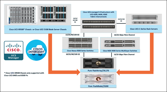
All FlashStack components are integrated, so you can deploy the solution quickly and economically while eliminating many of the risks associated with researching, designing, building, and deploying similar solutions from the foundation. One of the main benefits of FlashStack is its ability to maintain consistency at scale. Each of the component families shown in Figure above (Cisco UCS, Cisco Nexus, Cisco MDS, Pure Storage FlashArray and FlashBlade systems) offers platform and resource options to scale up or scale out the infrastructure while supporting the same features and functions.
The FlashStack solution with Cisco UCS X-Series uses the following hardware components:
● Cisco UCS X9508 chassis with any number of Cisco UCS X210c M7 compute nodes.
● Cisco UCS fourth-generation 6454 fabric interconnects to support 25- and 100-GE connectivity from various components.
● High-speed Cisco NXOS-based Nexus 93180YC-FX3 switching design to support up to 100-GE connectivity.
● Pure Storage FlashBlade//S500 scale-out file and object storage with 100GE connectivity to Cisco Nexus switching fabric.
● Pure FlashArray//XL170 storage with 25GbE connectivity to Cisco Nexus switching fabric and 32Gb FC connectivity to Cisco MDS switching fabric.
The software components consist of:
● Cisco Intersight platform to deploy, maintain, and support the FlashStack components.
● Cisco Intersight Assist virtual appliance to help connect the Pure Storage FlashArray and VMware vCenter with the Cisco Intersight platform.
● For virtualized clusters, VMware vCenter 8.0 to set up and manage the virtual infrastructure as well as integration of the virtual environment with Cisco Intersight software.
Cisco Unified Computing System
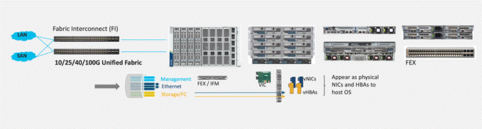
Cisco Unified Computing System (Cisco UCS) is a next-generation datacenter platform that integrates computing, networking, storage access, and virtualization resources into a cohesive system designed to reduce total cost of ownership and increase business agility. The system integrates a low-latency, lossless 10-100 Gigabit Ethernet unified network fabric with enterprise-class, x86-architecture servers. The system is an integrated, scalable, multi-chassis platform with a unified management domain for managing all resources.
Cisco Unified Computing System consists of the following subsystems:
● Compute—The compute piece of the system incorporates servers based on the Fourth Generation Intel Xeon Scalable processors. Servers are available in blade and rack form factor, managed by Cisco UCS Manager.
● Network—The integrated network fabric in the system provides a low-latency, lossless, 10/25/40/100 Gbps Ethernet fabric. Networks for LAN, SAN and management access are consolidated within the fabric. The unified fabric uses the innovative Single Connect technology to lower costs by reducing the number of network adapters, switches, and cables. This in turn lowers the power and cooling needs of the system.
● Virtualization—The system unleashes the full potential of virtualization by enhancing the scalability, performance, and operational control of virtual environments. Cisco security, policy enforcement, and diagnostic features are now extended into virtual environments to support evolving business needs.
Cisco Unified Computing System is revolutionizing the way servers are managed in the datacenter. The following are the unique differentiators of Cisco Unified Computing System and Cisco UCS Manager:
● Embedded Management—In Cisco UCS, the servers are managed by the embedded firmware in the Fabric Inter-connects, eliminating the need for any external physical or virtual devices to manage the servers.
● Unified Fabric—In Cisco UCS, from blade server chassis or rack servers to FI, there is a single Ethernet cable used for LAN, SAN, and management traffic. This converged I/O results in reduced cables, SFPs and adapters – reducing capital and operational expenses of the overall solution.
● Auto Discovery—By simply inserting the blade server in the chassis or connecting the rack server to the fabric interconnect, discovery and inventory of compute resources occurs automatically without any management intervention. The combination of unified fabric and auto-discovery enables the wire-once architecture of Cisco UCS, where compute capability of Cisco UCS can be extended easily while keeping the existing external connectivity to LAN, SAN, and management networks.
Cisco UCS Manager (UCSM) provides unified, integrated management for all software and hardware components in Cisco UCS. Using Cisco Single Connect technology, it manages, controls, and administers multiple chassis for thousands of virtual machines. Administrators use the software to manage the entire Cisco Unified Computing System as a single logical entity through an intuitive graphical user interface (GUI), a command-line interface (CLI), or through a robust application programming interface (API).
Cisco Unified Computing System X-Series
The Cisco Unified Computing System X-Series (Cisco UCSX) is a modular, next-generation data center platform that builds upon the unique architecture and advantages of the previous Cisco UCS 5108 system but with the following key enhancements that simplify IT operations:
● Cloud-managed infrastructure: With Cisco UCS X-Series, the management of the network infrastructure is moved to the cloud, making it easier and simpler for IT teams to respond quickly and at scale to meet the needs of your business. The Cisco Intersight cloud-operations platform allows you to adapt the resources of the Cisco UCS X-Series Modular System to meet the specific requirements of a workload. Additionally, you can seamlessly integrate third-party devices such as Pure Storage and VMware vCenter. This integration also enables global visibility, monitoring, optimization, and orchestration for all your applications and infrastructure.
● Adaptable system designed for modern applications: Today's cloud-native and hybrid applications are dynamic and unpredictable. Application and DevOps teams frequently deploy and redeploy resources to meet evolving requirements. To address this, the Cisco UCS X-Series provides an adaptable system that doesn't lock you into a fixed set of resources. It combines the density, manageability, and efficiency of blade servers with the expandability of rack servers, allowing you to consolidate multiple workloads onto a single platform. This consolidation results in improved performance, automation, and efficiency for both hybrid and traditional data center applications.
● Platform engineered for the future: The Cisco UCS X-Series is designed to adapt to emerging technologies with minimal risk. It is a modular system that can support future generations of processors, storage, nonvolatile memory, accelerators, and interconnects. This eliminates the need to purchase, configure, maintain, power, and cool separate management modules and servers. Cloud-based management through Intersight ensures automatic updates and access to new capabilities delivered through a software-as-a-service model.
● Broad support for diverse workloads: The Cisco UCS X-Series supports a broad range of workloads, reducing the need for different products which lowers support costs, training costs, and gives you more flexibility in your data center environment.
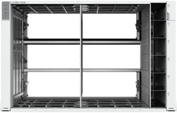
Cisco UCS X9508 Chassis
The Cisco UCS X-Series chassis is engineered to be adaptable and flexible. As shown in Figure 2, Cisco UCS X9508 chassis has only a power-distribution midplane. This innovative design provides fewer obstructions for better airflow. For I/O connectivity, vertically oriented compute nodes intersect with horizontally oriented fabric modules, allowing the chassis to support future fabric innovations. Cisco UCS X9508 Chassis’ superior packaging enables larger compute nodes, thereby providing more space for actual compute components, such as memory, GPU, drives, and accelerators. Improved airflow through the chassis enables support for higher power components, and more space allows for future thermal solutions (such as liquid cooling) without limitations.
The Cisco UCS X9508 7-Rack-Unit (7RU) chassis has eight flexible slots (Figure 3). These slots can house a combination of compute nodes and a pool of future I/O resources that may include GPU accelerators, disk storage, and nonvolatile memory.
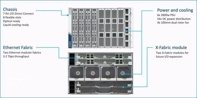
At the top rear of the chassis are two Intelligent Fabric Modules (IFMs) that connect the chassis to upstream Cisco UCS 6500 Series Fabric Interconnects. At the bottom rear of the chassis are slots ready to house future Cisco UCS X-Series fabric modules that can flexibly connect the compute nodes with I/O devices. Six 2800W Power Supply Units (PSUs) provide 54V power to the chassis with N, N+1, and N+N redundancy. A higher voltage allows efficient power delivery with less copper and reduced power loss. Efficient, 100mm, dual counter-rotating fans deliver industry-leading airflow and power efficiency, and optimized thermal algorithms enable different cooling modes to best support your environment.
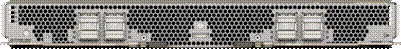
Cisco UCSX 9108-25G Intelligent Fabric Modules
For the Cisco UCS X9508 Chassis, the network connectivity is provided by a pair of Cisco UCSX 9108-25G Intelligent Fabric Modules (IFMs). Like the fabric extenders used in the Cisco UCS 5108 Blade Server Chassis, these modules carry all network traffic to a pair of Cisco UCS 6400 Series Fabric Interconnects (FIs). IFMs also host the Chassis Management Controller (CMC) for chassis management. In contrast to systems with fixed networking components, Cisco UCS X9508s midplane-free design enables easy upgrades to new networking technologies as they emerge making it straightforward to accommodate new network speeds or technologies in the future.
![]()
Each IFM supports eight 25Gb uplink ports for connecting the Cisco UCS X9508 Chassis to the FIs and 32 25Gb server ports for the eight compute nodes. IFM server ports can provide up to 200 Gbps of unified fabric connectivity per compute node across the two IFMs. The uplink ports connect the chassis to the Cisco UCS FIs, providing up to 400Gbps connectivity across the two IFMs. The unified fabric carries management, VM, and Fibre Channel over Ethernet (FCoE) traffic to the FIs, where management traffic is routed to the Cisco Intersight cloud operations platform, FCoE traffic is forwarded to the native Fibre Channel interfaces through unified ports on the FI (to Cisco MDS switches), and data Ethernet traffic is forwarded upstream to the datacenter network (via Cisco Nexus switches).
Cisco UCSX 9108-100G Intelligent Fabric Modules
The Cisco UCS 9108-100G and 9108-25G Intelligent Fabric Module (IFM) brings the unified fabric into the blade server enclosure, providing connectivity between the blade servers and the fabric interconnect, simplifying diagnostics, cabling, and management.
This FlashStack solution with Cisco UCS X-Series and 5th Generation Fabric technology uses Cisco UCS 9108 100G IFM.
The Cisco UCS 9108 100G IFM connects the I/O fabric between the 6536 Fabric Interconnect and the Cisco UCS X9508 Chassis, enabling a lossless and deterministic converged fabric to connect all blades and chassis together. Because the fabric module is similar to a distributed line card, it does not perform any switching and is managed as an extension of the fabric interconnects. This approach removes switching from the chassis, reducing overall infrastructure complexity, and enabling Cisco UCS to scale to many chassis without multiplying the number of switches needed, reducing TCO, and allowing all chassis to be managed as a single, highly available management domain. The Cisco UCS 9108 100G IFM also manages the chassis environment (power supply, fans, and blades) in conjunction with the fabric interconnect. Therefore, separate chassis-management modules are not required.
The IFM plugs into the rear side of the Cisco UCS X9508 chassis. The IFM provides a data path from the chassis compute nodes to the Cisco UCS 6536 Fabric Interconnect. Up to two Intelligent Fabric Modules (IFMs) plug into the back of the Cisco UCS X9508 chassis.
The IFMs serve as line cards in the chassis and multiplex data from the compute nodes to the Fabric Interconnect (FI). They also monitor and manage chassis components such as fan units, power supplies, environmental data, LED status panel, and other chassis resources. The server compute node Keyboard-Video-Mouse (KVM) data, Serial over LAN (SoL) data, and Intelligent Platform Management Interface (IPMI) data also travel to the IFMs for monitoring and management purposes. In order to provide redundancy and failover, the IFMs are always used in pairs.
There are 8 x QSFP28 external connectors on an IFM to interface with a Cisco UCS 6536 Fabric Interconnect. The IFM internally provides 1 x 100G or 4 x 25G connections towards each Cisco UCS X210c Compute Node in Cisco X9508 chassis.
Cisco UCS X210 M7 Server
The Cisco UCS X210 M7 server is a high-performance and highly scalable server designed for data centers and enterprise environments. Some of the key benefits of this server are:
● Performance: The Cisco UCS X210 M7 server is built to deliver exceptional performance. It features the latest Intel Xeon Scalable processors, providing high processing power for demanding workloads such as virtualization, database management, and analytics. The server's architecture is designed to optimize performance across a wide range of applications.
● Scalability: The Cisco UCS X210 M7 server offers excellent scalability options, allowing organizations to easily scale their computing resources as their needs grow. With support for up to eight CPUs and up to 112 DIMM slots, the server can accommodate large memory configurations and high core counts, enabling it to handle resource-intensive applications and virtualization environments.
● Memory Capacity: The server supports a large memory footprint, making it suitable for memory-intensive workloads. It can accommodate a vast amount of DDR4 DIMMs, providing a high memory capacity for applications that require significant data processing and analysis.
● Enhanced Virtualization Capabilities: The Cisco UCS X210 M7 server is designed to optimize virtualization performance. It includes features such as Intel Virtualization Technology (VT-x) and Virtual Machine Device Queues (VMDq), which improve virtual machine density and network performance in virtualized environments. These capabilities enable organizations to consolidate their workloads and achieve efficient resource utilization.
● Simplified Management: The Cisco Unified Computing System (Cisco UCS) management software provides a unified and streamlined approach to server management. The Cisco UCS Manager software allows administrators to manage multiple servers from a single interface, simplifying operations and reducing management complexity. Additionally, the server integrates with Cisco's ecosystem of management tools, providing enhanced visibility, automation, and control.
● High Availability and Reliability: The Cisco UCS X210 M7 server is built with redundancy and fault tolerance in mind. It includes features such as hot-swappable components, redundant power supplies, and redundant fans, ensuring high availability and minimizing downtime. The server's architecture is designed to support mission-critical applications that require continuous operation.
● Energy Efficiency: Cisco UCS servers are designed to be energy-efficient. The Cisco UCS X210 M7 server incorporates power management features that optimize power usage and reduce energy consumption. This not only helps organizations reduce their carbon footprint but also lowers operating costs over time.
Note: It's important to understand that the specific benefits and features may vary depending on the configuration and usage scenario. Organizations should evaluate their specific requirements and consult with Cisco or their authorized resellers to determine how the Cisco UCS X210 M7 server can best meet their needs.
Cisco UCS Virtual Interface Cards (VICs)
Cisco UCS X210c M7 Compute Nodes support multiple Cisco UCS VIC cards. This design uses the Cisco UCS VIC 15231 adapter.
Cisco UCS VIC 15231
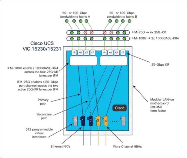
Cisco UCS VIC 15231 fits the mLOM slot in the Cisco X210c M7 Compute Node and enables up to 100 Gbps of unified fabric connectivity to each of the chassis IFMs for a total of 200 Gbps of connectivity per server.
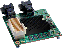
Cisco UCS VIC 15231 connectivity to the IFM-100G and up to the 5th Gen 6536 fabric interconnects is delivered through 2x 100-Gbps connections. The connections between Cisco UCS VIC 15231 and IFM-25Gs in Cisco UCS X-Series enabled 2X50Gbps connection per IFM.
Cisco UCS VIC 15231 supports 256 virtual interfaces (both Fibre Channel and Ethernet) along with the latest networking innovations such as NVMeoF over RDMA (ROCEv2), VxLAN/NVGRE/GENEVE offload, and so on.
Cisco UCS VIC 15428
The Cisco UCS VIC 15428 is a quad-port small-form-factor pluggable (SFP+/SFP28/SFP56) mLOM card designed for Cisco UCS C-Series M6/M7 rack servers. The card supports 10/25/50-Gbps Ethernet or FCoE. The card can present PCIe standards-compliant interfaces to the host, and these can be dynamically configured as either NICs or HBAs.
When a Cisco UCS rack server with a Cisco UCS VIC 15428 is connected to a fabric interconnect (FI-6536/6400/6300), the Cisco UCS VIC 15428 is provisioned via Cisco Intersight or Cisco UCS Manager (UCSM) policies. And when the Cisco UCS rack server with Cisco UCS VIC 15428 is connected to a ToR switch such as Cisco Nexus 9000 Series, the Cisco UCS VIC 15428 is provisioned through the Cisco IMC or Cisco Intersight policies for a standalone server.
Cisco UCS VIC 15238
The Cisco UCS VIC 15238 is a dual-port quad small-form-factor pluggable (QSFP/QSFP28/QSFP56) mLOM card designed for Cisco UCS C-Series M6 and M7 rack servers. The card supports 40/100/200-Gbps Ethernet or FCoE. The card can present PCIe standards-compliant interfaces to the host, and these can be dynamically configured as either NICs or HBAs.
When a Cisco UCS rack server with Cisco UCS VIC 15238 is connected to a Cisco UCS fabric interconnect (FI-6536/6300), the Cisco UCS VIC 15238 is provisioned through Cisco Intersight (IMM) or Cisco UCS Manager (UCSM) policies. And when the Cisco UCS rack server with Cisco UCS VIC 15238 is connected to a ToR switch such as Cisco Nexus 9000 Series, the Cisco UCS VIC 15238 is provisioned through the Cisco IMC or Intersight policies for a Cisco UCS standalone server.
Cisco UCS Fabric
Cisco UCS 6400 Series Fabric Interconnects
The Cisco UCS Fabric Interconnects (FIs) provide a single point of connectivity and management for the entire Cisco UCS system. Typically deployed as an active/active pair, the system’s FIs integrate all components into a single, highly available management domain controlled by the Cisco UCS Manager or Cisco Intersight. Cisco UCS FIs provide a single unified fabric for the system, with low-latency, lossless, cut-through switching that supports LAN, SAN, and management traffic using a single set of cables.
![]()
Cisco UCS 6454 utilized in the current design is a 54-port Fabric Interconnect. This single RU device includes 28 10/25 Gbps Ethernet ports, 4 1/10/25-Gbps Ethernet ports, 6 40/100-Gbps Ethernet uplink ports, and 16 unified ports that can support 10/25 Gigabit Ethernet or 8/16/32-Gbps Fibre Channel, depending on the SFP.
Note: To support the Cisco UCS X-Series, the fabric interconnects must be configured in Intersight Managed Mode (IMM). This option replaces the local management with Cisco Intersight cloud or appliance-based management.
5th Generation Cisco UCS Fabric Interconnects
The Cisco UCS Fabric Interconnects (FIs) provide a single point of connectivity and management for the entire Cisco UCS system. Typically deployed as an active/active pair, the system’s FIs integrate all components into a single, highly available management domain controlled by the Cisco UCS Manager or Cisco Intersight. Cisco UCS FIs provide a single unified fabric for the system, with low-latency, lossless, cut-through switching that supports LAN, SAN, and management traffic using a single set of cables.
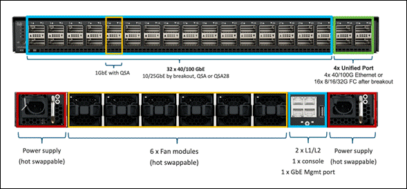
The Cisco UCS 6536 Fabric Interconnect utilized in the current design is a One-Rack-Unit (1RU) 1/10/25/40/100 Gigabit Ethernet, FCoE, and Fibre Channel switch offering up to 7.42 Tbps throughput and up to 36 ports. The switch has 32 40/100-Gbps Ethernet ports and 4 unified ports that can support 40/100-Gbps Ethernet ports or 16 Fiber Channel ports after breakout at 8/16/32-Gbps FC speeds. The 16 FC ports after breakout can operate as an FC uplink or FC storage port. The switch also supports two ports at 1-Gbps speed using QSA, and all 36 ports can breakout for 10- or 25-Gbps Ethernet connectivity. All Ethernet ports can support FCoE.
The Cisco UCS 6536 Fabric Interconnect (FI) is a core part of the Cisco Unified Computing System, providing both network connectivity and management capabilities for the system. The Cisco UCS 6536 Fabric Interconnect offers line-rate, low-latency, lossless 10/25/40/100 Gigabit Ethernet, Fibre Channel, NVMe over Fabric, and Fibre Channel over Ethernet (FCoE) functions.
The Cisco UCS 6536 Fabric Interconnect provides the communication backbone and management connectivity for the Cisco UCS X-Series compute nodes, Cisco UCS X9508 X-series chassis, Cisco UCS B-Series blade servers, Cisco UCS 5108 B-Series server chassis, and Cisco UCS C-Series rack servers. All servers attached to a Cisco UCS 6536 Fabric Interconnect become part of a single, highly available management domain. In addition, by supporting a unified fabric, Cisco UCS 6536 Fabric Interconnect provides both LAN and SAN connectivity for all servers within its domain.
From a networking perspective, the Cisco UCS 6536 uses a cut-through architecture, supporting deterministic, low-latency, line-rate 10/25/40/100 Gigabit Ethernet ports, a switching capacity of 7.42 Tbps per FI and 14.84 Tbps per unified fabric domain, independent of packet size and enabled services. It enables 1600Gbps bandwidth per X9508 chassis with X9108-IFM-100G in addition to enabling end-to-end 100G ethernet and 200G aggregate bandwidth per X210c compute node. With the X9108-IFM-25G and the IOM 2408, it enables 400Gbps bandwidth per chassis per FI domain. The product family supports Cisco low-latency, lossless 10/25/40/100 Gigabit Ethernet unified network fabric capabilities, which increases the reliability, efficiency, and scalability of Ethernet networks. The 6536 Fabric Interconnect supports multiple traffic classes over a lossless Ethernet fabric from the server through the fabric interconnect. Significant TCO savings come from the Unified Fabric optimized server design in which network interface cards (NICs), Host Bus Adapters (HBAs), cables, and switches can be consolidated.
Cisco UCS Unified Fabric: I/O Consolidation
The Cisco UCS 6536 Fabric Interconnect is built to consolidate LAN and SAN traffic onto a single unified fabric, saving on Capital Expenditures (CapEx) and Operating Expenses (OpEx) associated with multiple parallel networks, different types of adapter cards, switching infrastructure, and cabling within racks. The unified ports allow ports in the fabric interconnect to support direct connections from Cisco UCS to existing native Fibre Channel SANs. The capability to connect to a native Fibre Channel protects existing storage-system investments while dramatically simplifying in-rack cabling.
The Cisco UCS 6536 Fabric Interconnect supports I/O consolidation with end-to-end network virtualization, visibility, and QoS guarantees the following LAN and SAN traffic:
● FC SAN, IP Storage (iSCSI, NFS), NVMEoF (NVMe/FC, NVMe/TCP, NVMe over ROCEv2)
● Server management and LAN traffic
The I/O consolidation under the Cisco UCS 6536 fabric interconnect along with the stateless policy-driven architecture of Cisco UCS and the hardware acceleration of the Cisco UCS Virtual Interface card provides great simplicity, flexibility, resiliency, performance, and TCO savings for the customer’s compute infrastructure.
As applications and data become more distributed from core datacenter and edge locations to public clouds, a centralized management platform is essential. IT agility will be struggle without a consolidated view of the infrastructure resources and centralized operations. Cisco Intersight provides a cloud-hosted, management and analytics platform for all Cisco UCS and other supported third-party infrastructure across the globe. It provides an efficient way of deploying, managing, and upgrading infrastructure in the datacenter, ROBO, edge, and co-location environments.
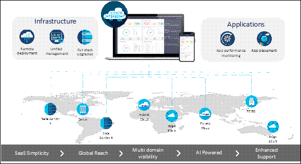
Cisco Intersight provides:
● No Impact Transition: The embedded connector within Cisco UCS allows you to start consuming benefits without a forklift upgrade.
● SaaS/Subscription Model: The SaaS model provides a centralized, cloud-scale management and operations across hundreds of sites around the globe without the administrative overhead of managing the platform.
● Enhanced Support Experience: The hosted platform enables Cisco to address issues platform-wide and experience extends into TAC supported platforms.
● Unified Management: A single pane of glass, consistent operations model, and experience for managing all systems and solutions.
● Programmability: End-to-end programmability with native API, SDK’s and popular DevOps toolsets will enable customers to consume natively.
● Single point of automation: Automation using Ansible, Terraform and other tools can be done through Cisco Intersight for all systems it manages.
● Recommendation Engine: Our approach with visibility, insight, and action powered by machine intelligence and analytics provide real-time recommendations with agility and scale. The embedded recommendation platform with insights sourced from across Cisco install base and tailored to each customer.
The main benefits of Cisco Intersight infrastructure services are as follows:
● Simplify daily operations by automating many daily manual tasks.
● Combine the convenience of a SaaS platform with the capability to connect from anywhere and manage infrastructure through a browser or mobile app.
● Stay ahead of problems and accelerate trouble resolution through advanced support capabilities.
● Gain global visibility of infrastructure health and status along with advanced management and support capabilities.
● Upgrade to add workload optimization when needed.
In this solution, Cisco Intersight unifies and simplifies the hybrid cloud operations of FlashStack datacenter components wherever they are deployed.
Cisco Intersight Virtual Appliance and Private Virtual Appliance
In addition to the SaaS deployment model running on Intersight.com, on-premises options can be purchased separately. The Cisco Intersight Virtual Appliance and Cisco Intersight Private Virtual Appliance are available for organizations that have additional data locality or security requirements for managing systems. The Cisco Intersight Virtual Appliance delivers the management features of the Cisco Intersight platform in an easy-to-deploy VMware Open Virtualization Appliance (OVA) or Microsoft Hyper-V Server virtual machine that allows you to control the system details that leave your premises. The Cisco Intersight Private Virtual Appliance is provided in a form factor specifically designed for users who operate in disconnected (air gap) environments. The Private Virtual Appliance requires no connection to public networks or back to Cisco to operate.
Cisco Intersight Assist and Device Connectors
Cisco Intersight Assist helps customers add endpoint devices to Cisco Intersight. A datacenter could have multiple devices that do not connect directly with Cisco Intersight. Any device that is supported by Cisco Intersight but does not connect to Intersight directly needs Cisco Intersight Assist to provide the necessary connectivity. In FlashStack, VMware vCenter and Pure Storage FlashArray connect to Intersight with the help of Intersight Assist appliance.
Cisco Intersight Assist is available within the Cisco Intersight Virtual Appliance, which is distributed as a deployable virtual machine contained within an Open Virtual Appliance (OVA) file format.
Cisco Intersight integrates with VMware vCenter and Pure Storage FlashArray as follows:
● Cisco Intersight uses the device connector running within Cisco Intersight Assist virtual appliance to communicate with the VMware vCenter.
● Cisco Intersight uses the device connector running within a Cisco Intersight Assist virtual appliance to integrate with Pure Storage FlashArray//XL170.
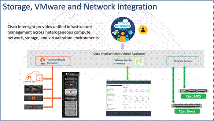
The device connector provides a safe way for connected targets to send information and receive control instructions from the Cisco Intersight portal using a secure Internet connection. The integration brings the full value and simplicity of Cisco Intersight infrastructure management service to VMware hypervisor and FlashArray storage environments. The integration architecture enables FlashStack customers to use new management capabilities with no compromise in their existing VMware or FlashArray operations. IT users will be able to manage heterogeneous infrastructure from a centralized Cisco Intersight portal. At the same time, the IT staff can continue to use VMware vCenter and the Pure Storage dashboard for comprehensive analysis, diagnostics, and reporting of virtual and storage environments. The next section addresses the functions that this integration provides.
The Cisco Nexus 9000 Series Switches offer both modular and fixed 1/10/25/40/100 Gigabit Ethernet switch configurations with scalability up to 60 Tbps of nonblocking performance with less than five-microsecond latency, wire speed VXLAN gateway, bridging, and routing support.
![]()
The Cisco Nexus 9000 series switch featured in this design is the Cisco Nexus 93180YC-FX3 configured in NX-OS standalone mode. NX-OS is a purpose-built data-center operating system designed for performance, resiliency, scalability, manageability, and programmability at its foundation. It provides a robust and comprehensive feature set that meets the demanding requirements of virtualization and automation.
The Cisco Nexus 93180YC-FX3 Switch is a 1RU switch that supports 3.6 Tbps of bandwidth and 1.2 bpps. The 48 downlink ports on the 93180YC-FX3 can support 1-, 10-, or 25-Gbps Ethernet, offering deployment flexibility and investment protection. The six uplink ports can be configured as 40- or 100-Gbps Ethernet, offering flexible migration options.
Cisco MDS 9132T 32G Multilayer Fabric Switch
The Cisco MDS 9132T 32G Multilayer Fabric Switch is the next generation of the highly reliable, flexible, and low-cost Cisco MDS 9100 Series switches. It combines high performance with exceptional flexibility and cost effectiveness. This powerful, compact one Rack-Unit (1RU) switch scales from 8 to 32 line-rate 32 Gbps Fibre Channel ports.
![]()
The Cisco MDS 9132T delivers advanced storage networking features and functions with ease of management and compatibility with the entire Cisco MDS 9000 family portfolio for reliable end-to-end connectivity. This switch also offers state-of-the-art SAN analytics and telemetry capabilities that have been built into this next-generation hardware platform. This new state-of-the-art technology couples the next-generation port ASIC with a fully dedicated network processing unit designed to complete analytics calculations in real time. The telemetry data extracted from the inspection of the frame headers are calculated on board (within the switch) and, using an industry-leading open format, can be streamed to any analytics-visualization platform. This switch also includes a dedicated 10/100/1000BASE-T telemetry port to maximize data delivery to any telemetry receiver, including Cisco Data Center Network Manager.
Red Hat OpenShift Container Platform
The Red Hat OpenShift Container Platform (OCP) is a container application platform that brings together CRI-O and Kubernetes and provides an API and web interface to manage these services. CRI-O is a lightweight implementation of the Kubernetes CRI (Container Runtime Interface) to enable using Open Container Initiative (OCI) compatible runtimes including runc, crun, and Kata containers.
OCP allows you to create and manage containers. Containers are standalone processes that run within their own environment, independent of the operating system and the underlying infrastructure. OCP helps develop, deploy, and manage container-based applications. It provides a self-service platform to create, modify, and deploy applications on demand, thus enabling faster development and release life cycles. OCP has a microservices-based architecture of smaller, decoupled units that work together and is powered by Kubernetes with data about the objects stored in etcd, a reliable clustered key-value store.
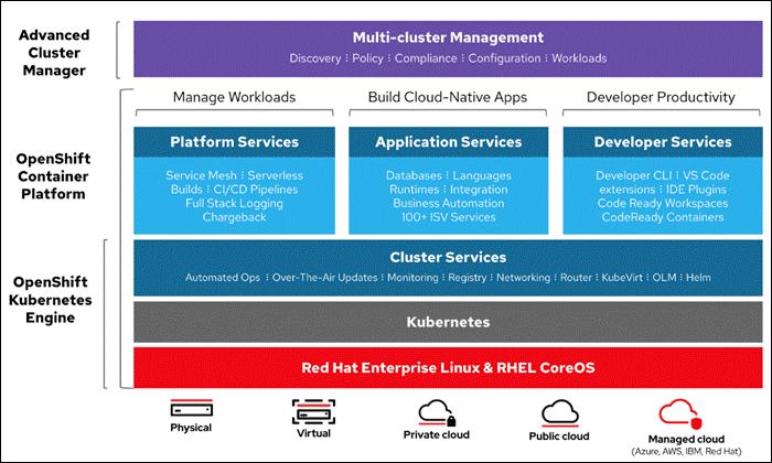
Some of the capabilities in Red Hat OCP include:
● Automated deployment of OCP clusters on-prem (bare metal, VMware vSphere, Red Hat OpenStack Platform, Red Hat Virtualization) and in public clouds.
● Automated upgrades of OCP clusters with seamless over-the-air upgrades initiated from the web console or OpenShift CLI (oc)
● Add services with push-button ease – Once a cluster is deployed, Red Hat OpenShift uses Kubernetes Operators to deploy additional capabilities and services on the cluster. Red Hat Certified and community supported operators are available in the embedded Operator Hub and can be deployed with the click of a button.
● Multi-cluster management using Red Hat’s cloud-based Hybrid Cloud Console or enterprise-managed Advance Cluster Management (ACM) provides a consolidated view of all clusters, with the ability to easily access and use other K8s technologies and services. OCP clusters can also be individually managed using a web-based cluster console or APIs.
● Persistent storage support – OCP provides support for a broad range of ecosystem storage partners including the Portworx Enterprise used in this solution.
● Scalability – OCP can scale to meet the largest and smallest compute use cases as needed.
● Automate container and application builds, deployments, scaling, cluster management, and more with ease.
● Self-service provisioning – Developers can quickly and easily create applications on demand from the tools they use most, while operations retain full control over the entire environment.
● Source-to-image deployment – OCP provides a toolkit and workflow for producing ready-to-run images by injecting source code into a container and letting the container prepare that source code for execution.
For more information, see: Red Hat OpenShift Container Platform product page on redhat.com.
Kubernetes Infrastructure
Within OpenShift Container Platform, Kubernetes manages containerized applications across a set of CRI-O runtime hosts and provides mechanisms for deployment, maintenance, and application scaling. The CRI-O service packages, instantiates, and runs containerized applications.
A Kubernetes cluster consists of one or more control plane nodes and a set of worker nodes. This solution design includes HA functionality at the hardware as well as the software stack. An OCP cluster is designed to run in HA mode with 3 control plane nodes and a minimum of 2 worker nodes to help ensure that the cluster has no single point of failure.
Red Hat Hybrid Cloud Console
Red Hat Hybrid Cloud Console is a centralized SaaS-based management console for deploying and managing multiple OCP clusters. It is used in this solution to provide consistent container management across a hybrid environment. The SaaS model enables Enterprises to develop, deploy, and innovate faster across multiple infrastructures and quickly take advantage of new capabilities without the overhead of managing the tool. The console gives Enterprises more control and visibility as environments grow and scale. The Hybrid Cloud Console also provides tools to proactively address issues, open and manage support cases, manage cloud costs, subscriptions, and more.
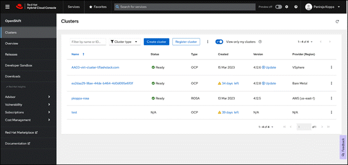
For more information, see: Red Hat Hybrid Cloud Console product page on redhat.com
Consumption Models
Red Hat OpenShift is available as a managed service by Red Hat and major cloud providers or as a self-managed service where the Enterprise manages and maintains the OCP cluster. Red Hat OCP as a managed service is hosted on major public clouds with Red Hat’s expert SRE teams providing a fully managed application platform, enabling the Enterprise to focus on its applications and core business. Red Hat OpenShift is a complete, production-ready application platform with additional services such as CI/CD pipelines, monitoring, security, container registry, service mesh, and more included on top of Kubernetes. Managed cloud-hosted OpenShift services include Red Hat OpenShift Service on AWS, Microsoft Azure Red Hat OpenShift, Red Hat OpenShift Dedicated on Google Cloud or AWS, and Red Hat OpenShift on IBM Cloud.
Installation Options
Red Hat Enterprise Linux CoreOS (RHCOS) is deployed automatically using configurations in the ignition files. The OCP installer creates the Ignition configuration files necessary to deploy the OCP cluster with RHCOS. The configuration is based on the user provided responses to the installer. These files and images are downloaded and installed on the underlying infrastructure by the installer.
● openshift-install is a command line utility for installing openshift in cloud environments and on-prem. It collects information from the user, generates manifests, and uses terraform to provision and configure infrastructure that will compose a cluster.
● Assisted Installer is a cloud-hosted installer available at https://console.redhat.com as both an API and a guided web UI. After defining a cluster, the user downloads a custom “discovery ISO” and boots it on the systems that will be provisioned into a cluster, at which point each system connects to console.redhat.com for coordination. Assisted installer offers great flexibility and customization while ensuring success by running an extensive set of validations prior to installation.
● agent-based installer is a command line utility that delivers the functionality of the Assisted Installer in a stand-alone format that can be run in disconnected and air-gapped environments, creating a cluster without requiring any other running systems besides a container registry.
● Red Hat Advanced Cluster Management for Kubernetes (see the section below) includes the Assisted Installer running on-premises behind a Kubernetes API in addition to a web UI. OpenShift’s bare metal platform features, especially the baremetal-operator, can be combined with the Assisted Installer to create an integrated end-to-end provisioning flow that uses Redfish Virtual Media to automatically boot the discovery ISO on managed systems.
Red Hat Enterprise Linux CoreOS (RHCOS)
RHCOS is a lightweight operating system specifically designed for running containerized workloads. It is based on the secure, enterprise-grade Red Hat Enterprise Linux (RHEL). RHCOS is the default operating system on all Red Hat OCP cluster nodes. RHCOS is tightly controlled, allowing only a few system settings to be modified using the Ignition configuration files. RHCOS is designed to be installed as part of an OCP cluster installation process with minimal user configuration. Once the cluster is deployed, the cluster will fully manage the RHCOS subsystem configuration and upgrades.
RHCOS includes:
● Ignition – for initial bootup configuration and disk related tasks on OCP cluster nodes
Ignition serves as a first boot system configuration utility for initially bringing up and configuring the nodes in the OCP cluster. Starting from a tightly-controlled OS image, the complete configuration of each system is expressed and applied using ignition. It also creates and formats disk partitions, writes files, creates file systems and directories, configures users etc. During a cluster install, the control plane nodes get their configuration file from the temporary bootstrap machine used during install, and the worker nodes get theirs from the control plane nodes. After an OCP cluster is installed, subsequent configuration of nodes is done using the Machine Config Operator to manage and apply ignition.
● CRI-O – Container Engine running on OCP cluster nodes
CRI-O is a stable, standards-based, lightweight container engine for Kubernetes that runs and manages the containers on each node. CRI-O implements the Kubernetes Container Runtime Interface (CRI) for running Open Container Initiative (OCI) compliant runtimes. OCP’s default container runtime is runc. CRI-O has a small footprint and a small attack surface, with an emphasis on security and simplicity. CRI-O is a Cloud Native Computing Foundation (CNCF) incubating project.
● Kubelet – Kubernetes service running on OCP cluster nodes
Kubelet is a Kubernetes service running on every node in the cluster. It communicates with the control plane components and processes requests for running, stopping, and managing container workloads.
● Set of container tools
Container Tools: RHCOS includes a set of container tools (including podman, skopeo, and crictl) for managing containers and container image actions such as start, stop, run, list, remove , build, sign, push, and pull.
● rpm-ostree combines RPM package management with libostree’s immutable content-addressable operating system image management. RHCOS is installed and updated using libostree, guaranteeing that the installed OS is in a known state, with transactional upgrades and support for rollback.
Note: RHCOS was used on all control planes and worker nodes to support the automated OCP 4 deployment.
Red Hat Advanced Cluster Management for Kubernetes
Red Hat Advanced Cluster Management for Kubernetes (ACM) controls clusters and applications from a single console, with built-in security policies. It extends the value of OpenShift by deploying apps, managing multiple clusters, and enforcing policies across multiple clusters at scale. Red Hat’s solution ensures compliance, monitors usage, and maintains consistency.
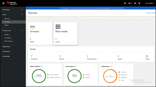
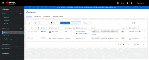
Running on Red Hat OpenShift, Red Hat Advanced Cluster Management for Kubernetes includes capabilities that unify multi-cluster management, provide policy-based governance, and extend application lifecycle management, as follows:
● Unified Multi-Cluster Management
◦ Centrally create, update, and delete Kubernetes clusters across multiple private and public clouds.
◦ Search, find, and modify any Kubernetes resource across the entire domain.
◦ Quickly troubleshoot and resolve issues across your federated domain.
◦ When creating or updating clusters, automate tasks such as configuring cloud-defined storage, static IP addresses, updating network components (like firewalls or load balancers), and more with the integration of Red Hat Ansible Automation Platform.
● Policy-based Governance, Risk, and Compliance
◦ Centrally set and enforce policies for security, applications, and infrastructure.
◦ Quickly visualize detailed auditing on configuration of apps and clusters.
◦ Immediate visibility into your compliance posture based on your defined standards.
◦ Automate remediation of policy violations and gather audit information about the clusters for analysis with the integration of Red Hat Ansible Automation Platform.
● Advanced Application Lifecycle Management
◦ Define and deploy applications across clusters based on policy.
◦ Quickly view service endpoints and pods associated with your application topology—with all the dependencies.
◦ Automatically deploy applications to specific clusters based on channel and subscription definitions.
◦ When deploying or updating applications, automate configurations like networking, databases, and more with the integration of Red Hat Ansible Automation Platform.
● Multi-cluster Observability for Health and Optimization
◦ Get an overview of multi-cluster health and optimization using out-of-the-box multi-cluster dashboards with the ability to store long-term data.
◦ Easily sort, filter, and do a deep scan of individual clusters or, at the aggregated multi-cluster level.
◦ Get an aggregated view of cluster metrics.
◦ Troubleshoot faster using the Dynamic Search and Visual Web Terminal capabilities.
● Multi-cluster Networking with Submariner
◦ Provide cross-cluster network infrastructure with Submariner for direct and encrypted communication.
◦ Use DNS service discovery for Kubernetes clusters connected by Submariner in multi-cluster environments.
◦ Uniformly manage and observe microservices-based applications network flow for behavioral insight, control, and troubleshooting.
Portworx Enterprise Kubernetes Storage and Data Management Platform
Portworx Enterprise is the multi cloud ready cloud defined storage platform for running mission critical applications. Portworx Enterprise is a fully integrated solution for persistent storage, disaster recovery, data security, cross-cloud data migrations, and automated capacity management for applications.
Portworx Enterprise provides container optimized storage for applications with no downtime with features like elastic scaling and a high availability solution across nodes/racks/AZs. Portworx Enterprise is designed to have consistent application performances by storage-aware class-of-service (COS) and application-aware I/O tuning.
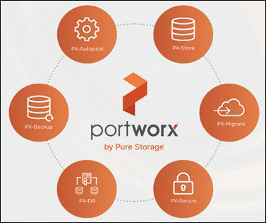
Portworx Enterprise secures the environment with encryption and access controls, provides cluster-wide encryption with container or storage class based BYOK encryption. Portworx Enterprise supports Role-based Access Control (RBAC) over both cluster operations and volume operations and integration with active directory and LDAP via OIDC.
For cloud native applications, Portworx Enterprise allows local, application-consistent/aware snapshots for multi-container applications. Portworx Autopilot for Capacity Management has the ability to automatically resize individual container volumes or your entire storage pools. Portworx Autopilot rules- based engine with customization capabilities can optimize apps based on performance requirements. Portworx Autopilot can easily integrate with multi clouds like Amazon EBS, Google PD, and Azure Block Storage.
Portworx Backup can capture entire applications, including data, application configuration, and Kubernetes objects/Metadata, and move them to any backup location at the click of a button and its point-and-click recovery for any Kubernetes app makes it easy for developers. Portworx Disaster Recovery has the ability to set DR policies at the container granular level and set multi-site synchronous and asynchronous replication for a near zero RPO DR across a metro area.
This solution explains use cases and features that help administrators deploy and operate a robust Kubernetes stack for their developers.
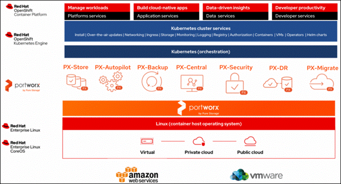
Use Cases and Features of Portworx Enterprise Kubernetes Storage Platform
PX-Store
PX-Store provides the following:
● Scalable persistent storage for Kubernetes and provides cloud native storage for applications running in the cloud, on-prem, and in hybrid/multi-cloud environments.
● High Availability across nodes/racks/AZs.
● Multi-writer shared volumes across multiple containers.
● Storage-aware class-of-service (COS) and application aware I/O tuning.
● Aggregated volumes for storage pooling across Hosts and provided volume consistency groups.
● Support for OpenStorage SDK and can be plugged into CSI, Kubernetes, and Docker volumes.
Portworx Autopilot
Autopilot is a rule-based engine that responds to changes from a monitoring source. Autopilot allows administrators to specify monitoring conditions along with actions it should take when those conditions occur. Autopilot requires a running Prometheus instance in your cluster.
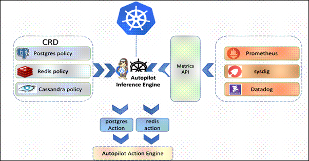
Automatically grow PVCs, expand, and rebalance Portworx storage pool cluster. Portworx APIs are used to expand storage pools across multi-cloud environments like Amazon EBS, Google PD, and Azure Block Storage, VMware vSphere. Scales at the individual volume or entire cluster level and saves money and avoids application outages.
Autopilot monitors the metrics in your cluster (for example, via Prometheus) and once high usage conditions occur, it can resize the PVC.PVC, Namespace selectors, metric conditions are used to resize the action.
AutopilotRule CRD suggests which objects, conditions to monitor, and the corresponding actions to perform. when conditions occur.
An AutopilotRule has the following main parts:
● Selector matches labels on the objects.
● Namespace Selector matches labels on the Kubernetes namespaces.
● Conditions the metrics for the objects to monitor.
● Actions to perform once the metric conditions are met. Action approvals can be done through kubectl or by setting up GitOps and Github.
Portworx Backup
Portworx Backup feature allows application level snapshots and can be recovered into any other cluster. PX-backup can be backed up to any public and hybrid cloud location and recovery is as simple as click of a button. Administrators can manage and enforce compliance and governance responsibilities with a single pane of glass for all containerized applications. Enabling application aware backup and fast recovery for even complex distributed applications.
Portworx Backup is capable of backing up the following resources: Persistent Volume (PV), Persistent Volume Claim (PVC), Deployment, StatefulSet, ConfigMap, Service, Secret, DaemonSet, ServiceAccount, Role, RoleBinding, ClusterRole, ClusterRoleBinding and Ingress.
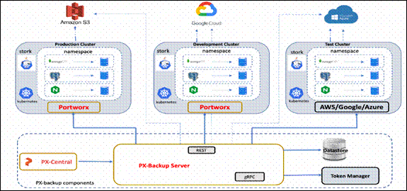
Portworx Backup components are as follows:
● Portworx Backup server: A gRPC server that implements the basic CRUD operations for objects like Cluster, Backup location, Cloud credential, Schedule policy, Backup, Restore and Backup schedule.
● Application clusters: A cluster in Portworx Backup is any Kubernetes cluster that Portworx Backup makes backups and restores from. It lists all applications and resources available on the cluster. Portworx Backup Server communicates with stork to create application-level backups and it monitors the CRDs on each cluster.
● Datastore: A MongoDB based Database where the Portworx Backup stores objects related to the cluster such as backup location, schedule policies, backup, restore, and backup schedule.
● Token Based Authentication: Communicates with an external service (Okta, KeyCloak, and so on) to validate and authorize tokens that are used for the API calls.
● Backups: Backups in Portworx Backup contain backup images and configuration data.
● Backup locations: A backup location is not tied to any particular cluster and can be used to trigger backups and restores on any cluster. Portworx Backup stores backups on any compatible object storage like AWS S3 or compatible object stores, Azure Blob Storage or Google Cloud Storage.
● Restores: Administrators can restore backups to the original cluster or different clusters, replace applications on the original cluster or restore to a new namespace.
● Schedule Policies: Schedule policies can be created and attached to backups to run them at designated times and designated number of rolling backups.
● Rules: Rules can be used to create commands which run before or after a backup operation is performed.
● Application view: Administrators can interact, create rules, backups with Portworx Backup through a central application view.
Portworx Central
Portworx Central on-premises GUI:
● Monitors the clusters using built-in dashboards
● Provides multi-cluster management
● Adds and manages Portworx licenses through the license server
● Views and manages the Portworx volumes and take snapshots.
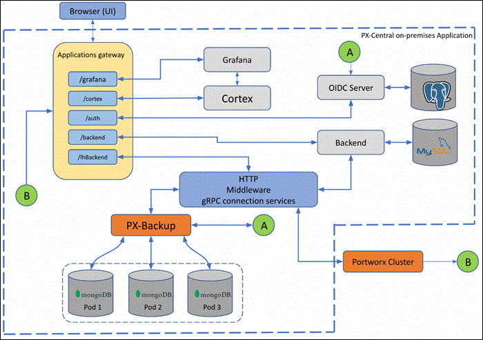
PX-Central Components:
● Application gateway: Uses the Nginx reverse proxy mechanism, where more than one service in the application gateway is exposed on an external network, all these services listen on HTTP or HTTPS.
● OIDC server: Manages the identity of users, groups, and roles of a user. Portworx Central uses KeyCloak (uses postgres as datastore) as a SSO server to enable user authorization.
● Backend service: Laravel PHP based service, manages active users and clusters added on Lighthouse. The backend service provides an option to save states at a user level or global level by making use of a MySQL database.
● Middleware service: A connector service used to interface multiple microservices and third party services to the UI. The middleware passes the token information to the corresponding services, and authorization happens directly at the provider service. The middleware service also provides a common data interface for error or success messages, paginated responses, pagination services and others.
Portworx Security
Portworx Security secures the containers with access controls and encryption. It includes cluster wide encryption and BYOK encryption with storage class or container granular based. Role based control for Authorization, Authentication, Ownership and integrates with Active Directory and LDAP.
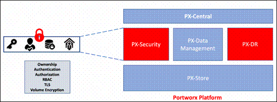
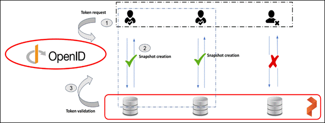
To authenticate users in Portworx, Portworx Security supports either OIDC or self-generated tokens. OpenID Connect (or OIDC) is a standard model for user authentication and management and it integrates with SAML 2.0, Active Directory, and/or LDAP. The second model is self-generated token validation. Administrators generate a token using their own token administration application, Portworx provides a method of generating tokens using the Portworx CLI (pxctl).
Portworx Disaster Recovery
Portworx Disaster Recovery offers a near RPO-zero failover across data centers in a metropolitan area network and in addition to HA within a single datacenter. PX-DR offers continuous incremental-backups and has the ability to set all DP policies at the container granular level.
Portworx provides two primary DR options, Metro DR, and asynchronous DR:
● Portworx Metro DR
◦ All the Portworx Nodes in all Kubernetes clusters are in the same Metro Area Network (MAN).
◦ The same cloud region. They can be in different zones.
◦ The network latency between the nodes is lower than ~10ms.
● Metro DR characteristics
◦ A single Portworx cluster that stretches across multiple Kubernetes clusters.
◦ Portworx installation on all clusters uses a common external key-value store (for example, etcd).
◦ Volumes are automatically replicated across the Kubernetes clusters as they share the same Portworx storage fabric.
◦ This option will have zero RPO and RTO in less than 60 seconds.
◦ witness node is a single virtual machine and a special Portworx storage-less node that participates in quorum but does not store any data.
◦ Metro DR needs a three node etcd cluster for Portworx. One etcd node needs to be running in each data center and one node should be running on the witness node.
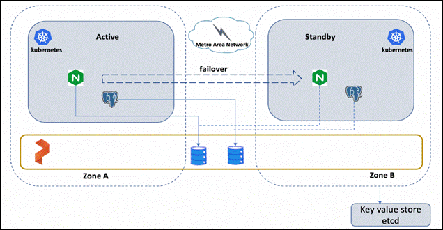
● Portworx Asynchronous DR
◦ Nodes in all your Kubernetes clusters are in the different regions or datacenter.
◦ The network latency between the nodes is high.
● Portworx Asynchronous DR characteristics
◦ A separate Portworx cluster installation for each Kubernetes clusters.
◦ Portworx installations on each cluster can use their own key-value store (for example, etcd).
◦ Administrators can create scheduled migrations of applications and volumes between 2 clusters that are paired.
◦ This option will have an RPO of 15 minutes and RTO less than 60 second
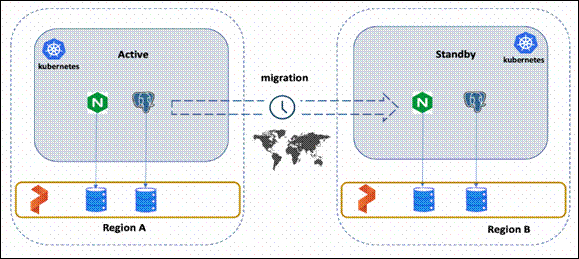
Portworx Migrate
Portworx migrate provides the ability to move or migrate applications between heterogeneous K8s clusters. Apps can be developed in-cloud and can be migrated on-prem or between clusters and a very useful feature during cluster maintenance and upgrades.
● Portworx Migrate most used cases
◦ Testing: Administrators can test and validate new versions on the Portworx or the Container cluster versions by seamlessly moving applications across clusters.
◦ Capacity planning: Administrators can free capacity on critical clusters by moving non-critical applications to other secondary clusters.
◦ Development and Testing: Administrators can promote workloads from dev to staging clusters without any disruptions.
◦ Cloud mobility: Move applications and data from an on-prem cluster to a hosted AWS EKS or Google GKE.
◦ Upgrade and Maintenance: Administrators can migrate applications and perform hardware-level upgrades.
● Characteristics of Portworx Migrate
◦ Pairing clusters - Establish trust relationship between a pair of clusters.
◦ Administrators can migrate all namespaces or specific namespace from Source to destination clusters.
◦ Migration with Stork on Kubernetes on Kubernetes moves application objects, configuration, data, Kubernetes Objects, Kubernetes Configuration and Portworx volumes.
Figure 28 shows the namespace with “dev” is migrated from Source cluster to Destination cluster. Administrators can migrate all namespaces or specific ones.
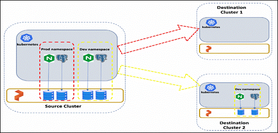
STORK
STORK (Storage Orchestrator Runtime for Kubernetes) allows stateful applications to take advantage of scheduler extenders in order to enjoy the benefits of storage-aware scheduling via Kubernetes in production at scale. Using a scheduler extender, STORK provides hyperconvergence, failure-domain awareness, storage health monitoring and snapshot-lifecycle features for stateful applications on Kubernetes.
In Figure 29, you can see how STORK health monitoring helps to reschedule the PODs to healthy Nodes in the event of a failure. Stork helps in these cases by failing over pods when the storage driver on a node goes into an error or unavailable state and ensures the applications to be truly Highly Available without any user intervention.
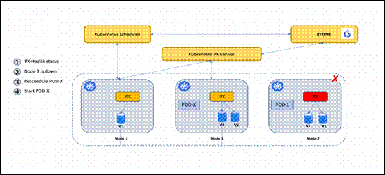
Monitoring Portworx Cluster
Portworx cluster can be monitored by Prometheus to collect data, Alertmanager to provide notifications and Grafana to visualize your data. Prometheus Alertmanager handles alerts sent from the Prometheus server based on rules you set. You can connect to Prometheus using Grafana to visualize your data. Grafana is a multi-platform open source analytics and interactive visualization web application. It provides charts, graphs, and alerts.
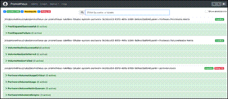
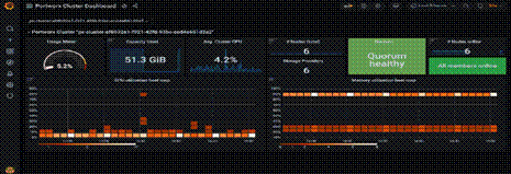
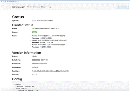
The primary highlights of the FlashArray//XL series are:
● Increased capacity and performance: FlashArray//XL is designed for today’s higher-powered multicore CPUs, which allows FlashArray//XL to increase performance over our FlashArray//X models. Provides more space for fans and airflow, which improves cooling efficiency, and for wider controllers that enable performance to scale today and well into future generations of FlashArray//XL. With greater storage density, FlashArray//XL supports up to 40 DirectFlash Modules in the main chassis.
● Increased connectivity, greater reliability, and improved redundancy: FlashArray//XL doubles the host I/O ports compared to FlashArray//X, for up to 36 ports per controller, and the //XL model provides more expansion slots for configuration flexibility. It doubles the bandwidth for each slot, including full bandwidth for mixed protocols. FlashArray//XL offers multiple 100GbE RDMA over Converged Ethernet (RoCE) links that are very robust to hot-plug and provide faster controller failover speed.
● DirectFlash Modules with distributed NVRAM: DirectFlash Modules include onboard distributed non-volatile random-access memory (DFMD). With DFMD, NVRAM capacity, NVRAM write bandwidth, and array capacity scale with the number of DFMDs, lifting the limit on write throughput.
● DirectCompress Accelerator: Included with every FlashArray//XL shipment, the DirectCompress Accelerator (DCA) increases compression efficiency by offloading inline compression to a dedicated PCIe card. It ensures maximum compression rates, even when the system is under a heavy load, and stretches capacity to reduce overall storage costs and to extend the value of your FlashArray//XL.
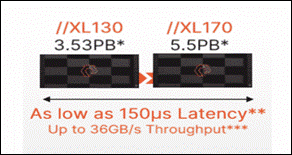
Table 1. FlashArray technical specifications
|
|
Capacity |
Physical |
| //XL170 |
Up to 5.5PB / 5.13PiB effective capacity* |
5-11U; 1850-2355W(nominal-peak) |
| Up to 1.4PB / 1.31PiB raw capacity** |
167lbs (75.7kg) fully loaded;8.72” x 18.94” x 29.72”** |
|
| //XL130 |
Up to 3.53PB / 3.3PiB effective capacity |
5-11U; 1550-2000 watts(nominal-peak) |
| Up to 968TB / 880TiB raw capacity |
167lbs (75.7kg) fully loaded; 8.72” x 18.94” x 29.72 |
|
| DirectFlash Shelf |
Up to 1.9PB effective capacity |
Up to 512TB / 448.2TiB raw capacity |
| 3U; 460-500 watts (nominal–peak) |
87.7lbs (39.8kg) fully loaded; 5.12” x 18.94” x 29.72” |
Table 2. FlashArray Connectivity
| Connectivity |
|
| Onboard Ports
● 2 x 1Gb (RJ45)
|
I/O Expansion Cards (6slots/controller) 2-port 10/25 Gb Ethernet, NVMe/TCP, NVMe/RoCE 2-port 40/100Gb Ethernet, NVMe/TCP, NVMe/RoCE 2-port 16/32/64†Gb FCP, NVMe/FC 4-port 16/32/64 Gb FCP, NVMe/FC |
| Management Ports
● 1 x RJ45 Serial
● 1 x VGA
● 4 x USB 3.0
|
Advantages of using FlashArray as Backend Storage for Portworx Enterprise
Pure Storage FlashArray provides all-flash storage backed by an enterprise-class array with six-nines reliability, data-at-rest encryption, and industry-leading data-reduction technology. Although Portworx supports any storage type including Direct Attached Storage (DAS) and Array based storage, using Portworx replicas to ensure data availability for application pods across nodes, then having all replicas provisioned from the same underlying FlashArray will multiply your standard data-reduction rate, for the application data, by the number of replicas for the persistent volume.
Portworx combined with Pure Storage FlashArray can be used as a cloud storage provider. This allows administrators to store your data on-premises with FlashArray while benefiting from Portworx cloud drive features, automatically provisioning block volumes, Expanding a cluster by adding new drives or expanding existing ones with support for Portworx Autopilot. Pure Storage FlashArray with Portworx on Kubernetes can attach FlashArray as a Direct Access volume. Used in this way, Portworx directly provisions FlashArray volumes, maps them to a user PVC, and mounts them to pods. FlashArray Direct Access volumes support the CSI operations like filesystem operations. snapshots and QOS.
Container ready infrastructure - Portworx on top of Pure Storage FlashArray to benefit from Kubernetes-native storage and data management. Operate, scale, and secure modern applications and databases on FlashArray and FlashBlade with just a few clicks.
Purity for FlashArray (Purity//FA 6)
Purity is secure, highly scalable, and simple to use, Purity powers all of Pure Storage, including FlashArray//X and FlashArray//XL to deliver comprehensive data services for performance and latency sensitive applications. Purity delivers the industry’s most granular and complete data reduction for unmatched storage efficiency. Purity’s “encrypt everything” approach provides built-in enterprise grade data security without user intervention or key management. Maintain regulatory compliance and help achieve GDPR compliance with FIPS 140-2 validated encryption, and impact-free, AES-256 data-at-rest encryption. Purity ensures business continuity by reducing your risk of downtime while keeping mission-critical applications and data online and accessible. Designed from the ground up for flash, Purity RAID-HA protects against concurrent dual-drive failures and initiates rebuilds automatically within minutes and detects and heals bit-errors. Purity integration with VMware Site Recovery Manager (SRM) lets your automation software orchestrate application recovery and mobility across sites. Purity 6.x delivers additional enhancements, capabilities, and solutions that customers can adopt immediately, non-disruptively, and as part of the Evergreen subscription to innovation.
FlashBlade//S is the ideal data storage platform for AI, as it was purpose-built from the ground up for modern, unstructured workloads and accelerates AI processes with the most efficient storage platform at every step of your data pipeline. A centralized data platform in a deep learning architecture increases the productivity of AI engineers and data scientists and makes scaling and operations simpler and more agile for the data architect. Its unified fast file and object (UFFO) system sets new standards for performance, scalability, and simplicity in high-capacity storage of file and object data. flash blade-based systems seamlessly integrate hardware, software, and networking, providing increased storage density with reduced power consumption and heat generation compared to other systems.
Purity//FB - Purity functions as a distributed storage operating environment where all blades within a system operate on identical software. Data is accessed through a common back-end "engine" by both file (NFS and SMB) and object (S3) protocols, automatically distributing front-end and back-end data processes across all blades. Consequently, the system continuously optimizes its performance without requiring administrators to manually relocate data sets, adjust operational parameters, or shut down for expansions and upgrades. This seamless process supports projects throughout their lifecycle, from model development and I/O-intensive training to full production. It can handle billions of files and objects and delivers unmatched performance for any workload, whether it’s with sequential or random access or with large or small IO sizes. Purity//FB delivers a rich set of enterprise capabilities including compression, always-on encryption, SafeMode, file replication, object replication, and many other features.
Performance with varying I/O loads: Achieving diverse performance is crucial in deep learning, where multiple gigabytes per second I/O rates are often necessary for training neural network models in applications such as machine vision, natural language processing, and anomaly detection. FlashBlade//S Storage systems deliver the required performance to prevent GPU data starvation and optimizes job completion time, ensuring developer productivity. FlashBlade//S does this by providing consistent performance at various I/O sizes and profiles, at capacity scale. FlashBlade//S, being an all-flash system, eliminates mechanical motion to access data, offering the same access time for every file and object, irrespective of size. It treats all I/O requests fairly, supporting data scientists in developing models, handling training jobs with intensive random I/O loads and checkpoint writes, and managing production I/O within a single system. As projects mature and necessitate system expansion, FlashBlade//S automatically adapts data placement and I/O distribution to effectively utilize all available resources.
Parallel file operations: RapidFile Toolkit, accessible to all FlashBlade users, leverages Purity//FB’s parallel operation. The toolkit significantly accelerates various operations essential in AI projects, including data movement, enumeration, deletion, and metadata modification. For extremely large datasets with millions of files or more, RapidFile Toolkit can accomplish tasks within minutes that traditionally take hours using conventional operating system utilities. Tasks such as creating copies, changing ownership, and randomizing billions of files to prevent overfitting contribute to expediting AI model development.
Data reliability and resiliency: Ensuring robust resilience in infrastructure becomes increasingly crucial as the significance of AI grows within an organization. Storage systems that result in prolonged downtime or require extensive administrative outages can result in costly project delays and disruptions in service. Many existing storage systems lack the capability to meet these demands or introduce excessive complexity in deployment and management for architects and administrators.
FlashBlade's reliability, demonstrated by the successful deployment of thousands of systems, effectively addresses these challenges. Purity//FB provides protection against data loss arising from DirectFlash module (DFM) and blade failures. In case of a component failure, it automatically initiates distributed rebuilds, swiftly restoring complete protection. And crucially, it does so without any complexity burden on the user or administrator, automatically configuring proper resiliency schemas based on system state. Reliability is paramount for maintaining the productivity of data scientists, ensuring a consistently reliable access to storage. As projects transition into production and wield influence over critical business decisions, the significance of data and its dependable accessibility becomes paramount.
Scalable capacity: Achieving scalable capacity is crucial for prosperous machine learning initiatives that involve continuous data acquisition and ongoing training needs, leading to a sustained increase in data volume over time. Additionally, enterprises succeeding in one AI project often extend these powerful techniques to new application domains, leading to further data expansion to accommodate diverse use cases. Storage platforms with rigid capacity limits impose significant administrative burdens to manage diverse pools of data effectively.
Pure Storage FlashBlade//S, with its scale-out, all-flash architecture and a distributed file system built for massive concurrency across all data types, is the only storage system that delivers on all of these characteristics while keeping the required configuration and management complexity to a minimum. FlashBlade//S seamlessly scales from terabytes to petabytes in one name space by simply adding more chassis, blades, and flash modules.
FlashBlade//S systems range from 168TB to 19.2PB of physical capacity (about 180TB to 25PB of effective storage) and are available in both capacity-optimized and performance-optimized configurations. With a committed roadmap of denser DFMs, the maximum capacity of FlashBlade systems will only increase over time.

Advanced Hardware and Software Working Together: FlashBlade//S includes the industry-leading Purity//FB software, designed together to maximize the power of Pure’s innovative FlashBlade hardware. This gives you visibility across all workloads and removes the complexity of managing storage by combining performance, capacity, and networking onto a single and unified platform. It provides native multiprotocol access for NFS, S3, and SMB and can support billions of files and objects in a single system. From tens of terabytes to tens of petabytes of data, FlashBlade//S is designed to easily scale out to grow with your unstructured data needs for analytics, artificial intelligence (AI) and machine learning (ML), data protection and rapid restore, high performance computing (HPC), and other data-driven file and object use cases in the areas of healthcare, genomics, electronic design automation (EDA) and advanced semiconductor design, financial services, and more.
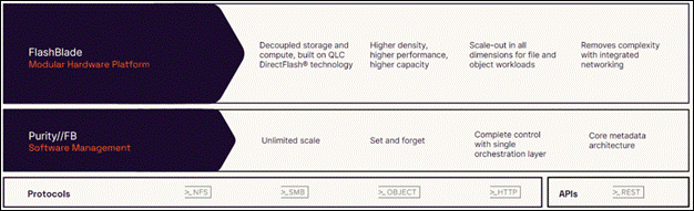
Ease of use: Simplicity and ease-of-use have been enduring characteristics of Pure Storage since the company's inception, and FlashBlade//S is a prime example of this commitment. Internal connections are streamlined through chassis midplanes, reducing cabling complexity and simplifying expansion processes. The software-defined networking is straightforward to set up and requires no additional management as the system scales. Administrators can effortlessly create file systems and object buckets using CLI or GUI interfaces by specifying names and size limits, with automatic handling of placement, allocation, and dynamic tuning. REST APIs facilitate the integration of FlashBlade//S administration with datacenter automation tools. Pure1 serves as a centralized monitoring tool for all organizational systems, enabling remote troubleshooting and upgrades by Pure's customer support teams.
FlashBlade//S ensures non-disruptive expansion and upgrades to accommodate varying storage needs throughout different AI project stages, ensuring smooth workflow operations. Administrators can easily repurpose capacity with a few simple keystrokes. This simplicity of operations minimizes training requirements, easing operations even as data center personnel change. In summary, FlashBlade//S administration stands out as one of the simplest tasks within a production data center.
Table 3. FlashBlade//S technical specifications
|
|
Scalability |
Physical |
Capacity |
Connectivity |
| FlashBlade//S
|
Start with a minimum of 7 blades and scale up to 10 blades in a single chassis* |
Up to 4 DirectFlash Modules per blade (24TB or 48TB DirectFlash Modules) |
Uplink networking 8 x 100GbE
|
5U per chassis Dimensions: 8.59” x 17.43” x 32.00” x 32.00” |
| Independently scale capacity and performance with all-QLC architecture |
Up to 192TB per blade |
Future-proof midplane |
2,400W (nominal at full configuration) |
Advantages of using FlashBlade as a Direct Access filesystem for Portworx Enterprise
On-premises users who want to use Pure Storage FlashBlade with Portworx on Kubernetes can attach FlashBlade as a Direct Access filesystem. Used in this way, Portworx directly provisions FlashBlade NFS filesystems, maps them to a user PVC, and mounts them to pods. Once mounted, Portworx writes data directly onto FlashBlade. As a result, this mounting method doesn't use storage pools.
FlashBlade Direct Access filesystems support the following:
● Basic filesystem operations: create, mount, expand, unmount, delete
● NFS export rules: Control which nodes can access an NFS filesystem
● Mount options: Configure connection and protocol information
Pure1, the cloud-based as-a-service data-management platform from Pure Storage, raises the bar in what you can expect. Pure1 delivers a single AI-driven hub that’s automated with the Pure1 Meta virtual assistant. You can accomplish common and complex data-management tasks with ease. It’s simple to purchase new or additional services from the service catalog. With Pure1, you can expand anytime, identify problems before they happen, and effortlessly plan for the future.
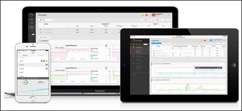
● Optimize
Pure1 creates a cloud-based storage management tool that’s simple and easy to use without sacrificing enterprise features. With Pure1, you can deliver IT outcomes in seconds vs. hours or days. You can eliminate costly downtime by leveraging predictive analytics and respond to dynamic changes quickly by accessing Pure1 from anywhere in the world.
● Centralized Setup and Monitoring
Setting up Pure1 using the Pure1 portal. As soon as your system is online, Pure1 Meta works in gathering analytics. Live monitoring is available within minutes and accessible from anywhere in the world.
● Full-stack Analysis
Access critical information about the health and functioning of your entire stack, including predictive fault analysis, and alerting.
● Reporting
Pure1 has an intuitive, built-in reporting engine that you can use to generate shareable reports on commonly requested information such as capacity, performance, or even service subscription status.
● Streamline
Elevate your data services experience with Pure1’s built-in AIOps powered by Pure1 Meta. This industry-leading, AI-driven platform for predictive service management ensures a higher level of data availability and performance. You can see all your data service platforms, whether on-premises FlashArray, Cloud Block Store in Azure or Amazon Web Services, or the Portworx Enterprise container storage platform from one place.
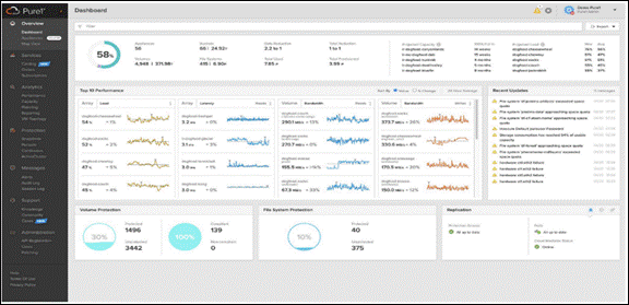
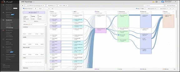
● Intelligent Monitoring and Management
Manage your entire fleet of Pure Storage systems from any device, with just a web browser or the Pure1 mobile application. Pure1 leverages AI to deliver industry-first capabilities that dramatically simplify management and planning. With Pure1, there simply won’t be much for you to do. If something does require attention, the Pure1 mobile app will let you know.
● Analyze
Full-stack analytics (VMA) extends beyond storage, and Pure1 has long featured deep analytics on your storage infrastructure. Pure1 now extends that visibility up the stack to give you deep performance metrics on volumes and VMs in your VMware environments, enabling fast and efficient troubleshooting with visibility throughout the stack. You now have insight into latency, bandwidth, and IOPs of your workflows—and the data point you need to resolve issues quickly and pinpoint latency problems or other bottlenecks.
● Infrastructure Optimization
The Service Assistant regularly checks the Pure1 cloud to determine if the storage infrastructure is running the latest software version. If it is not, it generates alerts to inform the IT team of upgrades to improve operating performance, add new features, and increase reliability. This feature is designed to investigate all Pure portfolio components and is extensible to other alliance offerings. You can expect this feature to expand to support end-to-end infrastructure.
Infrastructure as Code with Red Hat Ansible
Red Hat Ansible is an open-source tool for Infrastructure as Code (IaC). Ansible is also used for configuration management and application software deployment. Ansible is designed to be agentless, secure, and simple. Ansible available in Red Hat’s Ansible Automation Platform is part of a suite of tools supported by Red Hat. Ansible manages endpoints and infrastructure components in an inventory file, formatted in YAML or INI. The inventory file can be a static file populated by an administrator or dynamically updated. Passwords and other sensitive data can be encrypted using Ansible Vault. Ansible uses playbooks to orchestrate provisioning and configuration management. Playbooks are written in human readable YAML format that is easy to understand. Ansible playbooks are executed against a subset of components in the inventory file. From a control machine, Ansible uses SSH or Windows Remote Management to remotely configure and provision target devices in the inventory based on the playbook tasks.
Ansible is simple and powerful, allowing users to easily manage various physical devices within FlashStack including the configuration of Cisco UCS bare metal servers, Cisco Nexus switches, Pure FlashArray storage and VMware vSphere. Using Ansible’s Playbook-based automation is easy and integrates into your current provisioning infrastructure. This solution offers Ansible Playbooks that are made available from a GitHub repository that customers can access to automate the FlashStack deployment.
VMware vSphere 8.0 has several improvements and simplifications including, but not limited to:
● Limits with vSphere 8 have been increased including number of GPU devices is increased to 8, the number of ESXi hosts that can be managed by Lifecycle Manager is increased from 400 to 1000, the maximum number of VMs per cluster is increased from 8,000 to 10,000, and the number of VM DirectPath I/O devices per host is increased from 8 to 32.
● Security improvements including adding an SSH timeout on ESXi hosts, a TPM Provisioning policy allowing a vTPM to be replaced when cloning VMs, and TLS 1.2 as the minimum supported TLS version.
● Implementation of VMware vMotion Unified Data Transport (UDT) to significantly reduce the time to storage migrate powered off virtual machines.
● Lifecycle Management improvements including VMware vSphere Configuration Profiles as a new alternative to VMware Host Profiles, staging cluster images and remediating up to 10 ESXi hosts in parallel instead of one at a time.
● New Virtual Hardware in VM hardware version 20 supporting the latest guest operating systems, including Windows 11.
● Distributed Resource Scheduler and vMotion improvements.
● Implementation of the VMware Balanced Power Management Policy on each server, which reduces energy consumption with minimal performance compromise.
● Implementation of VMware Distributed Power Management, which along with configuration of the Intelligent Platform Management Interface (IPMI) on each UCS server allows a VMware host cluster to reduce its power consumption by powering hosts on and off based on cluster resource utilization.
For more information about VMware vSphere and its components, go to: https://www.vmware.com/products/vsphere.html
The Challenges of Building and Maintaining an AI Software Platform
AI is profoundly changing how business is done, and while organizations understand the transformative potential of AI, the implementation of this rapidly evolving technology is challenging.
For many enterprises, maintaining a consistent, secure, and stable software platform for building and running AI is a complex undertaking. Consider the foundation software used in AI, which includes over 4,500 unique software packages, 64 of which are NVIDIA CUDA libraries and more than 4,471 are third-party and open-source software (OSS) packages.
With this number of software packages, there’s a high risk of introducing security vulnerabilities. What’s more, maintaining API stability with the 10,000 dependencies between these unique software packages is another challenge, making it nearly impossible for enterprises to reliably use the latest open-source versions for their deployment environments.
Challenges of Production AI
● Complexity: Pulling together an end-to-end AI software stack from disparate, open- source software—and integrating them with existing infrastructure—is difficult.
● Risk: The AI software stack consists of thousands of open-source packages and dependencies, making security patching a challenge.
● Reliability: Maintaining a high- performance AI platform and managing API stability across the stack are critical for investment protection and business continuity.
Enterprise-Grade Software for Accelerated AI
Security, reliability, and manageability are critical for enterprise-grade AI. NVIDIA AI Enterprise is an end-to-end, cloud native software platform that accelerates the data science pipeline and streamlines development and deployment of production- grade AI applications, including generative AI, computer vision, speech AI, and more. Enterprises that run their businesses on AI rely on the security, support, and stability provided by NVIDIA AI Enterprise to improve productivity of AI teams, reduce total cost of AI infrastructure, and ensure a smooth transition from pilot to production.
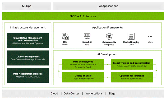
NVIDIA AI Enterprise includes:
● NVIDIA NeMo, an end-to-end framework for building, customizing, and deploying enterprise-grade generative AI models; NeMo lets organizations easily customize pretrained foundation models—from NVIDIA and select community models—for domain-specific use cases.
● Continuous monitoring and regular releases of security patches for critical and common vulnerabilities and exposures (CVEs).
● Production branches and long-term support branches that ensure API stability.
● End-to-end management software, including cluster management across cloud and data center environments and cloud-native orchestration.
● Enterprise support with service-level agreements (SLAs) and access to NVIDIA AI experts.
Accelerated AI Improves Productivity and Lowers TCO
With an extensive catalog of AI frameworks, pretrained models, and development tools optimized for building and running AI on NVIDIA GPUs, NVIDIA AI Enterprise accelerates every stage of the AI journey, from data prep and model training through inference and deployment at scale:
● Accelerate data processing up to 5X and reduce operational costs up to 5X over CPU-only platforms with the NVIDIA RAPIDSTM Accelerator for Apache Spark.
● Train at scale with the NVIDIA TAO Toolkit. Create custom, production-ready AI models in hours, rather than months, by fine-tuning NVIDIA pretrained models— without AI expertise or large training datasets.
● Accelerate large language model (LLM) inference performance up to 8X with NVIDIA TensorRT-LLM and inference performance up to 40X with Tensor over CPU-only platforms, lowering infrastructure and energy costs. .
● Deploy at scale with NVIDIA Triton Inference Server, which simplifies and optimizes the deployment of AI models at scale and in production for both neural networks and tree-based models on GPUs.
NVIDIA Triton Inference Server
NVIDIA Triton Inference Server is open-source inference serving software that helps standardize AI model deployment and execution in production from all major AI frameworks on any GPU- or CPU-based infrastructure.
Features
● High performance and utilization are achieved on both GPU and CPU systems through request batching and concurrent model execution.
● Stringent application latency service-level agreements (SLAs) for real-time and offline batched inference and large language models (LLMs) come with support for multi-GPU, multi-node execution and model ensembles.
● PyTriton provides a simple interface that lets Python developers use Triton Inference Server to serve anything, be it a model, a simple processing function, or an entire inference pipeline.
● Triton standardizes AI model deployment for all applications across cloud and edge, and it’s in production at world-leading companies—Amazon, Microsoft, American Express, and thousands more.
● Triton’s model analyzer can shrink model deployment time from weeks to days. It helps select the optimal deployment configuration to meet the application’s latency, throughput, and memory requirements.
Key Benefits of NVIDIA AI Inference
● Standardized deployment: Standardize model deployment across applications, AI frameworks, model architectures, and platforms.
● Easy integration: Integrate easily with tools and platforms on public clouds, in on-premises data centers, and at the edge.
● Lower cost: Achieve high throughput and utilization from AI infrastructure, thereby lowering costs.
● Seamless scalability: Scale inference jobs seamlessly across one or more GPUs.
● High performance: Experience incredible performance with the NVIDIA inference platform, which has set records across multiple categories in MLPerf, the leading industry benchmark for AI.
NVIDIA TensorRT, is an SDK for high-performance deep learning inference, includes a deep learning inference optimizer and a runtime that deliver low latency and high throughput for inference applications. TensorRT can be deployed, run, and scaled with Triton.
Key features
● Built on the NVIDIA CUDA parallel programming model, TensorRT optimizes techniques such as quantization, layer and tensor fusion, kernel tuning, and many more on NVIDIA GPUs.
● TensorRT provides INT8 using quantization-aware training and post-training quantization and floating point 16 (FP16) optimizations for deployment of deep learning inference applications, such as video streaming, recommendations, anomaly detection, and natural language processing.
● Integrations with all major frameworks, including Pytorch and TensorFlow, allow users to achieve 6X faster inference with a single line of code.
NVIDIA TensorRT-LLM is an open-source library that accelerates and optimizes inference performance of the latest LLMs on NVIDIA GPUs. It enables developers to experiment with new LLMs, offering speed-of-light performance with quick customization capabilities without deep knowledge of C++ or CUDA optimization.
TensorRT-LLM wraps TensorRT’s Deep Learning Compiler, optimized kernels from FasterTransformer, pre- and post-processing, and multi-GPU/multi-node communication in a simple open-source Python API for defining, optimizing, and executing LLMs for inference in production.
Text-Generation-Inference(TGI) is another toolkit for deploying and serving Large Language Models. TGI enables high-performance text generation using Tensor Parallelism and dynamic batching for the most popular open-source LLMs, including StarCoder, BLOOM, GPT-NeoX, Llama, and T5.
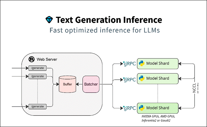
Text Generation Inference implements many optimizations and features, such as:
● Simple launcher to serve most popular LLMs.
● Production ready (distributed tracing with Open Telemetry, Prometheus metrics).
● Tensor Parallelism for faster inference on multiple GPUs.
● Token streaming using Server-Sent Events (SSE).
● Continuous batching of incoming requests for increased total throughput.
● Optimized transformers code for inference using Flash Attention and Paged Attention on the most popular architectures.
● Quantization with bitsandbytes and GPT-Q.
● Safetensors weight loading.
● Watermarking with A Watermark for Large Language Models.
● Logits warper (temperature scaling, top-p, top-k, repetition penalty).
● Stop sequences.
● Log probabilities.
● Custom Prompt Generation: Easily generate text by providing custom prompts to guide the model’s output.
● Fine-tuning Support: Utilize fine-tuned models for specific tasks to achieve higher accuracy and performance.
Text Generation Inference is used in production by multiple projects, such as:
● Hugging Chat, an open-source interface for open-access models, such as Open Assistant and Llama.
● OpenAssistant, an open-source community effort to train LLMs in the open.
● nat.dev, a playground to explore and compare LLMs.
This solution provides a reference architecture for Generative AI inferencing in the enterprises using NVIDIA A100 80GB PCIe GPU and NVIDIA L40-48C PCIe GPUs.
NVIDIA A100 TENSOR CORE GPU
The NVIDIA A100 Tensor Core GPU is the flagship product of the NVIDIA data center platform for deep learning, HPC, and data analytics. The platform accelerates over 2,000 applications, including every major deep learning framework. As the engine of the NVIDIA data center platform, the A100 provides up to 20X higher performance over the prior NVIDIA Volta generation. A100 can efficiently scale up or be partitioned into seven isolated GPU instances with Multi-Instance GPU (MIG), providing a unified platform that enables elastic data centers to dynamically adjust to shifting workload demands.
NVIDIA A100 Tensor Core technology supports a broad range of math precisions, providing a single accelerator for every workload. The latest generation A100 80GB doubles GPU memory and debuts the world’s fastest memory bandwidth at 2 terabytes per second (TB/s), speeding time to solution for the largest models and most massive datasets.
The A100 is part of the complete NVIDIA data center solution that incorporates building blocks across hardware, networking, software, libraries, and optimized AI models and applications from the NVIDIA NGC catalog. Representing the most powerful end-to-end AI and HPC platform for data centers, it allows researchers to deliver real-world results and deploy solutions into production at scale.
Table 4. NVIDIA A100 Tensor Core GPU Specifications
|
|
A100 80GB PCIe |
| GPU Architecture |
NVIDIA Ampere Architecture |
| GPU Memory |
80GB HBM2e |
| GPU Memory Bandwidth |
1,935GB/s |
| FP32 Cores / GPU |
6912 |
| Tensor Cores/GPU |
432 |
| FP64 |
9.7 TFLOPS |
| FP64 Tensor Core |
19.5 TFLOPS |
| FP32 |
19.5 TFLOPS |
| Tensor Float 32 (TF32) |
156 TFLOPS |
| BFLOAT16 Tensor Core |
312 TFLOPS |
| FP16 Tensor Core |
312 TFLOPS |
| INT8 Tensor Core |
624 TOPS |
| Max Thermal Design Power (TDP) |
300W |
| Form Factor |
PCe |
| Multi-Instance GPU |
Up to 7 MIGs @ 10GB |
NVIDIA L40
From virtual workstation application to large-scale modeling and simulation, modern visual computing and scientific workflows are growing in both complexity and quantity. Enterprises need data center technology that can deliver extreme performance and scale with versatile capabilities to conquer the diverse computing demands of these increasingly complex workloads.
The NVIDIA L40 GPU delivers unprecedented visual computing performance for the data center, providing next-generation graphics, compute, and AI capabilities. Built on the revolutionary NVIDIA Ada Lovelace architecture, the NVIDIA L40 harnesses the power of the latest generation RT, Tensor, and CUDA cores to deliver groundbreaking visualization and compute performance for the most demanding data center workloads.
Powered by the NVIDIA Ada Lovelace Architecture Third-Generation RT Cores
Enhanced throughput and concurrent ray-tracing and shading capabilities improve ray-tracing performance, accelerating renders for product design and architecture, engineering, and construction workflows. See lifelike designs in action with hardware-accelerated motion blur to deliver stunning real-time animations.
Fourth-Generation Tensor Cores
Hardware support for structural sparsity and optimized TF32 format provides out-of-the-box performance gains for faster AI and data science model training. Accelerate AI-enhanced graphics capabilities, including DLSS, delivering upscaled resolution with better performance in select applications.
Large GPU Memory
Tackle memory-intensive applications and workloads like data science, simulation, 3D modeling, and rendering with 48GB of ultra-fast GDDR6 memory. Allocate memory to multiple users with vGPU software to distribute large workloads among creative, data science, and design teams.
Data-Center Ready
Designed for 24x7 enterprise data center operations with power-efficient hardware and components, the NVIDIA L40 is optimized to deploy at scale and deliver maximum performance for a diverse range of data center workloads. The L40 includes secure boot with root of trust technology providing an additional layer of security and is NEBS Level 3 compliant to meet the latest data center standards. Packaged in a dual-slot, passively cooled and power-efficient design, the L40 is available in a wide variety of NVIDIA-Certified Systems from leading OEM vendors.
Table 5. NVIDIA L40 GPU Specifications
|
|
A100 80GB PCIe |
| GPU Architecture |
NVIDIA Ada Lovelace architecture |
| GPU Memory |
48GB GDDR6 with ECC |
| GPU Memory Bandwidth |
864GB/s |
| Interconnect Interface |
PCIe Gen4x16: 64GB/s bi-directional |
| NVIDIA Ada Lovelace architecture-based CUDA Cores |
18,176 |
| NVIDIA third-generation RT Cores |
142 |
| NVIDIA fourth-generation Tensor Cores |
568 |
| RT Core performance TFLOPS |
209 |
| FP32 TFLOPS |
90.5 |
| MIG Support |
No |
Kubernetes provides access to special hardware resources such as NVIDIA GPUs, NICs, Infiniband adapters and other devices through the device plugin framework. However, configuring and managing nodes with these hardware resources requires configuration of multiple software components such as drivers, container runtimes or other libraries which are difficult and prone to errors. The NVIDIA GPU Operator uses the operator framework within Kubernetes to automate the management of all NVIDIA software components needed to provision GPU. These components include the NVIDIA drivers (to enable CUDA), Kubernetes device plugin for GPUs, the NVIDIA Container Toolkit, automatic node labelling using GFD, DCGM based monitoring and others.
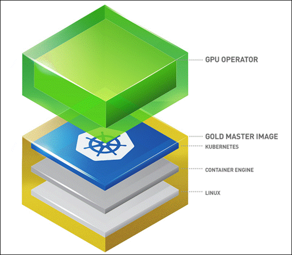
NVIDIA Virtual GPU (vGPU) enables multiple virtual machines (VMs) to have simultaneous, direct access to a single physical GPU, using the same NVIDIA graphics drivers that are deployed on non-virtualized operating systems.
The following steps are involved in deploying NVIDIA AI Enterprise for VMware vSphere with RedHat OpenShift Container Platform.
● Step 1: Install Node Feature Discovery (NFD) Operator
● Step 2: Install NVIDIA GPU Operator
● Step 3: Create the NGC secret
● Step 4: Create the ConfigMap
● Step 5: Create the Cluster Policy
This chapter contains the following:
● VMware vSphere – ESXi Design
● Pure Storage FlashArray – Storage Design
● Pure Storage FlashBlade – Storage Design
● Cisco Intersight Integration with FlashStack
● OCP Virtual Networking Design
● Portworx Enterprise Kubernetes Storage Platform Design Considerations
This solution provides a foundational reference architecture for Generative AI inferencing in the enterprises. It is designed to address the complexities of deploying and serving Generative AI models in production.
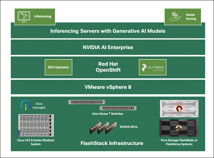
This solution consists of:
● Cisco UCS X-series based FlashStack Datacenter providing Compute, Storage, and networking infrastructure.
● Cisco UCS X210c M7 Compute Nodes in Cisco UCS X9508 Chassis are mapped with Cisco UCS X440p PCle Node to install GPUs.
● Pure Storage FlashArray//XL170 for scale-up Block & File.
● Pure Storage FlashBlade//S200 for scale-out File & Object.
● VMware vSphere 8.0 cluster is formed with Cisco UCS X210c M7 Compute Nodes.
● Each compute node is equipped with the supported NVDIA GPUs.
● NVIDIA AI Enterprise Host Software is installed on the VMware ESXi host server. This software enables multiple VMs to share a single GPU, or if there are multiple GPUs in the server, they can be aggregated so that a single VM can access multiple GPUs. Physical NVIDIA GPUs can support multiple virtual GPUs (vGPUs) and be assigned directly to guest VMs under the control of NVIDIA’s AI Enterprise Host Software running in a hypervisor. This Host Software is responsible for communicating with the NVIDIA vGPU guest driver which is installed on the guest VM.
● Red Hat OpenShift 4.14 cluster deployed on VMware vSphere 8.0 (Installer-provisioned infrastructure). Control plane and worker nodes are running as virtual machines on VMware vSphere 8.0 cluster.
● Virtual GPUs are added to the worker nodes.
● NVIDIA GPU Operator is installed and configured in Red Hat OpenShift. The GPU Operator uses the operator framework within OpenShift to automate the management of all NVIDIA software components needed to provision GPU. These components include the NVIDIA drivers (to enable CUDA), Kubernetes device plugin for GPUs, the NVIDIA Container Toolkit, automatic node labelling, DCGM based monitoring and others.
● Portworx Enterprise backed by FlashArray and NFS volumes from FlashBlade serves as model repository and provides storage and other data services for applications running in the FlashStack Datacenter.
● Toolkit for deploying and serving Generative AI models like NVIDIA Inference Container, Hugging Face Text Generation Inference, PyTorch etc. are installed and configured on OpenShift.
● Large Language Models and other Generative AI models are running on the inferencing servers.
FlashStack Datacenter - Infrastructure Options
Compute
The infrastructure for this design guide is FlashStack Datacenter incorporating the Cisco UCS X210c M7 Compute Node, Cisco Unified Computing System with 4th Generation Fabric Technology (4th Generation Fabric Interconnects 6454 and Cisco UCS X9108-IFM-25G IFM) into the Pure Storage FlashArray//XL170 to enable 25G Ethernet and 32G Fibre Channel.
However, end-to-end 100 Gigabit network connectivity in FlashStack datacenter with Cisco UCS 5th Generation Fabric Technology (5th Generation Fabric Interconnects 6536, 5th Generation Cisco UCS Virtual Interface Card and Cisco UCS X9108-IFM-100G IFM) can also be used based on requirement.
Storage
This solution is validated with Portworx Enterprise storage backed by Pure Storage FlashArray as well NFS target from Pure Storage FlashBlade for model repository. Combination or any one of the storage options can be used.
Figure 42 illustrates the end-to-end solution that was designed, built, and validated in Cisco internal labs.
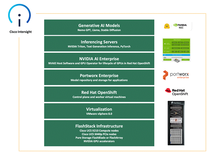
FlashStack Datacenter in this design delivers 25GbE solution with 32Gb FC and FC-NVMe based storage, iSCSI, NVMe-TCP, and NVMe-RoCEv2 based IP/Ethernet storage, and NFS storage. The solution includes the latest generation of Cisco UCS hardware running VMware vSphere 8.0. The solution incorporates design, technology, and product best practices to deliver a highly scalable and available architecture with no single point of failure.
The compute, storage, network, and virtualization layers of the end-to-end design is built using the following components:
● Cisco UCS X9508 server chassis with 2 x Cisco UCS X9108-25G Intelligent Fabric Modules (IFMs) where 4 x 25GbE ports on each IFM connect to a pair of Cisco UCS Fabric Interconnects to provide upstream connectivity and all networks within and outside the Enterprise data center, including external networks.
● Cisco UCS X210c M7 compute nodes using 2 x 4th generation Intel Xeon Scalable processors with 256GB of DDR5 memory that can be increased up to a max of 8TB. The server is equipped with a Cisco UCS VIC 15231 network adaptor in the modular LAN On Motherboard (mLOM) slot and provides up to 100Gbps (2x50Gbps) of unified fabric connectivity from each compute node to the 25G Intelligent Fabric Modules (IFMs) on the Cisco UCS X-Series chassis. IFM-25G enables 50Gbps port channel across the two active 25G-KR lanes per IFM.
● A pair of Cisco UCS 6454 Fabric Interconnects (FIs) provides line-rate, low-latency, lossless connectivity for LAN, SAN and management traffic from the Cisco UCS X-Series and Cisco UCS C-Series servers to Pure Storage and other upstream and external networks. The Cisco Fabric Interconnects provide:
◦ 4 x 32Gb FC connectivity to a Pure Storage FlashArray//XL170 through a pair of Cisco MDS switches.
◦ 2x25GbE uplink network connectivity to a pair of Cisco Nexus switches deployed in a vPC configuration and provide uplink connectivity to other internal and external networks.
● A pair of Cisco Nexus 93360YC-FX2 switches in NX-OS mode provide upstream connectivity to the Cisco UCS 6536FIs, enabling 100Gbps or higher speeds for connecting the FlashStack compute and storage infrastructure to other parts of an Enterprise’s internal and external networks as needed. The Cisco Nexus switches also connect to Pure Storage FlashArray using 25GbE to connect to Flash Array.
● A pair of Cisco MDS 9132T FC switches provide 32Gbps Fibre Channel connectivity to a SAN fabric with consistent low-latency performance using a chip-integrated non-blocking arbitration. MDS can operate in either switch mode or NPV mode and includes a dedicated Network Processing Unit (NPU) per port for real-time analytics calculations. The switch can inspect FC and SCSI headers at wire speed on every flow and analyze the flows on the switch itself. By using an industry-leading open format, the telemetry data can then be streamed to any analytics-visualization platform. This switch also includes a dedicated 10/100/1000BASE-T telemetry port to maximize data delivery to any telemetry receiver including Cisco Data Center Network Manager. Note that since this solution uses Cisco UCS 6454 FIs running in NPV mode, the MDS switches will not be used in NPV mode in this CVD. Instead, the MDS switches will be deployed in Fibre Channel switching mode with NPIV mode.
● Pure Storage FlashArray//XL170 connects to the Cisco MDS 9132T switches using 32-Gbps Fibre Channel connections for Fibre Channel SAN connectivity. The Pure Storage FlashArray//XL170 also connects to the Cisco Nexus 93360YC-FX2 switches using 25Gb Ethernet ports for FlashArray block (iSCSI, NVMe-TCP, NVMe-RoCEv2) services.
● Pure Storage FlashBlade//S200 connects to the Cisco Nexus 93360YC-FX2 switches using 100Gb Ethernet ports for File services(NFS).
● VMware vSphere 8.0 is deployed on the Cisco UCS X210M7 servers.
● Red Hat OpenShift 4.14 is installed on VMware vSphere 8.0, and it hosts all the inference servers/backends and deploy the Generative AI models.
● Cisco Intersight in Intersight Managed Mode (IMM) will manage the infrastructure from the cloud.
● NVIDIA A100 and L40 GPUs are installed in the Cisco UCS X210c M7 compute nodes. NVIDIA AI Enterprise Host Software packaged as a vSphere Installation Bundle (VIB) is installed on the host server. This software enables multiple VMs to share a single GPU.
● NVIDIA GPU Operator installs NVIDIA AI Enterprise Guest Driver. GPU operator manages the lifecycle of software components so GPU accelerated applications can be run on Kubernetes.
When NVIDIA AI Enterprise is running on VMware vSphere based virtualized infrastructure, a key component is NVIDIA virtual GPU. The NVIDIA AI Enterprise Host Software vSphere Installation Bundle (VIB) is installed on the VMware ESXi host server, and it is responsible for communicating with the NVIDIA vGPU guest driver which is installed on the guest VM. Guest VMs use the NVIDIA vGPUs in the same manner as a physical GPU that has been passed through by the hypervisor.
● Inferencing Servers like Triton Inference Server, Text Generation Inference are installed on OpenShift cluster. Regular Pytorch or Python also can also be used as backend for inferencing.
● Generative AI Models including Large Language Models and non- Large Language Models are running for inferencing.
The FlashStack VSI is designed to be highly available with redundancy at all layers of the stack (compute, storage, networking) including cabling and connectivity between components in the solution.
IP-based Storage Access
The physical topology for the IP-based FlashStack is shown in Figure 43.
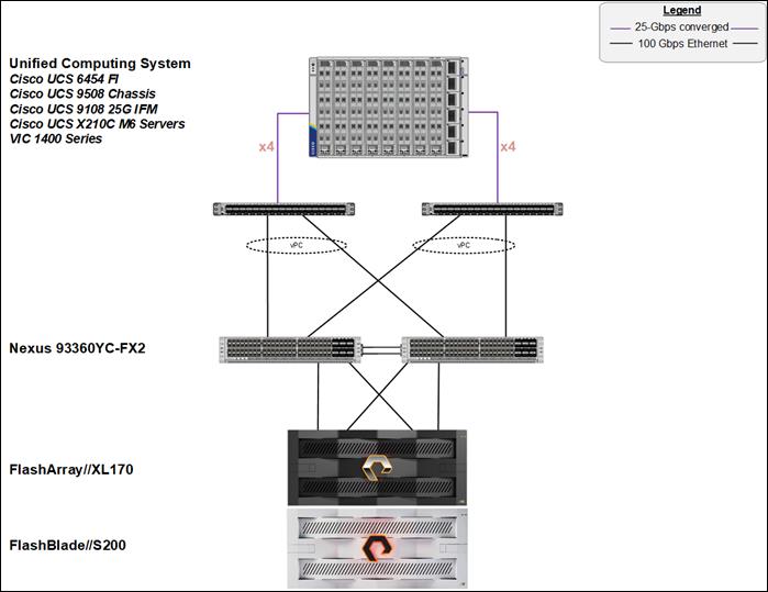
Fibre Channel-based Storage Access: FC and FC-NVMe
The physical topology of the FlashStack for FC connectivity is shown in Figure 44.
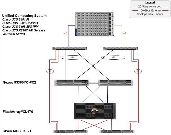
Compute Infrastructure Design
The compute infrastructure in FlashStack VSI solution consists of the following:
● Cisco UCS X210c M7 Compute Node
● Cisco UCS X-Series chassis (Cisco UCSX-9508) with Intelligent Fabric Modules (Cisco UCSX-I-9108-25G)
● Cisco UCS Fabric Interconnects (Cisco UCS-FI-6454)
The Cisco UCS X9508 Chassis is equipped with the Cisco UCSX 9108-25G intelligent fabric modules (IFMs). The Cisco UCS X9508 Chassis connects to each Cisco UCS 6454 FI using four 25GE ports, as shown in Figure 45. If you require more bandwidth, all eight ports on the IFMs can be connected to each FI.
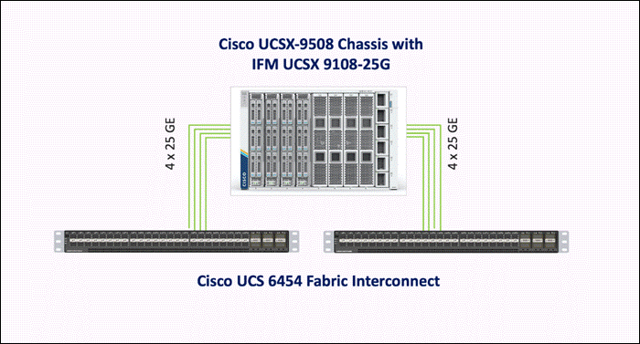
Cisco UCS Fabric Interconnects
The Cisco UCS 6454 Fabric Interconnects provide SAN, LAN, and management connectivity to and from the Cisco UCS Servers. The Cisco UCS/ESXi hosts, and the workloads hosted on the infrastructure use the Fabric Interconnects to access fibre channel and IP/Ethernet storage on Pure Storage and for reachability to Enterprise internal networks and for networks outside the Enterprise (for example, Cisco Intersight, Pure Storage Pure1).
In this design, the Cisco UCS Fabric Interconnects and the servers attached to it are managed remotely from the cloud in Intersight Managed Mode (IMM). IMM enables the Cisco UCS infrastructure to be completely managed from Cisco Intersight, including port configuration, firmware management, troubleshooting and server configuration using pools, policies, profiles, and server profile templates.
Cisco Nexus Ethernet Connectivity
The Cisco Nexus 93360YC-FX2 device configuration covers the core networking requirements for Layer 2 and Layer 3 communication. Some of the key NX-OS features implemented within the design are:
● Feature interface-vlan – Allows for VLAN IP interfaces to be configured within the switch as gateways.
● Feature HSRP – Allows for Hot Standby Routing Protocol configuration for high availability.
● Feature LACP – Allows for the utilization of Link Aggregation Control Protocol (802.3ad) by the port channels configured on the switch.
● Feature vPC – Virtual Port-Channel (vPC) presents the two Nexus switches as a single “logical” port channel to the connecting upstream or downstream device.
● Feature LLDP - Link Layer Discovery Protocol (LLDP), a vendor-neutral device discovery protocol, allows the discovery of both Cisco devices and devices from other sources.
● Feature NX-API – NX-API improves the accessibility of CLI by making it available outside of the switch by using HTTP/HTTPS. This feature helps with configuring the Cisco Nexus switch remotely using the automation framework.
● Feature UDLD – Enables unidirectional link detection for various interfaces.
Cisco UCS Fabric Interconnect 6454 Ethernet Connectivity
Cisco UCS 6454 FIs are connected to Cisco Nexus 93360YC-FX2 switches using 100GE connections configured as virtual port channels. Each FI is connected to both Cisco Nexus switches using a 100G connection; additional links can easily be added to the port channel to increase the bandwidth as needed. Figure 46 illustrates the physical connectivity details.
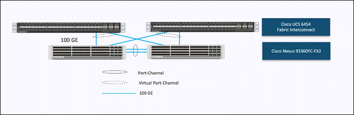
Pure Storage FlashArray//XL170 Ethernet Connectivity
Pure Storage FlashArray controllers are connected to Cisco Nexus 93360YC-FX2 switches using redundant 100-GE. Figure 47 illustrates the physical connectivity details.
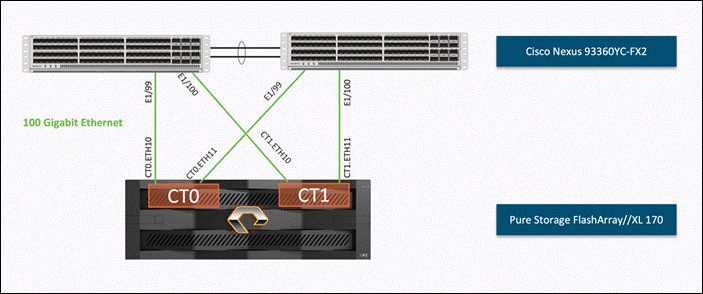
Pure Storage FlashBlade//S500 Ethernet Connectivity
Pure Storage FlashBlade uplink networking (8 x 100GbE) are connected to Cisco Nexus 93360YC-FX2 switches using redundant 100-GE. Figure 48 illustrates the physical connectivity details.
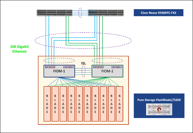
Cisco MDS SAN Connectivity – Fibre Channel Design
The Cisco MDS 9132T is the key design component bringing together the 32Gbps Fibre Channel (FC) capabilities to the FlashStack design. A redundant 32 Gbps Fibre Channel SAN configuration is deployed utilizing two MDS 9132Ts switches. Some of the key MDS features implemented within the design are:
● Feature NPIV – N port identifier virtualization (NPIV) provides a means to assign multiple FC IDs to a single N port.
● Feature fport-channel-trunk – F-port-channel-trunks allow for the fabric logins from the NPV switch to be virtualized over the port channel. This provides nondisruptive redundancy should individual member links fail.
● Smart-Zoning – a feature that reduces the number of TCAM entries by identifying the initiators and targets in the environment.
Cisco UCS Fabric Interconnect 6454 SAN Connectivity
For SAN connectivity, each Cisco UCS 6454 Fabric Interconnect is connected to a Cisco MDS 9132T SAN switch using 2 x 32G Fibre Channel port-channel connection, as shown in Figure 49.
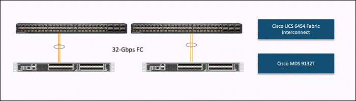
Pure Storage FlashArray//XL170 SAN Connectivity
For SAN connectivity, each FlashArray controller is connected to both of Cisco MDS 9132T SAN switches using 32G Fibre Channel connections, as shown in Figure 50.
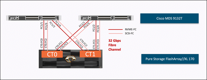
Cisco UCS X-Series Configuration - Cisco Intersight Managed Mode
Cisco Intersight Managed Mode standardizes policy and operation management for Cisco UCS X-Series. The compute nodes in Cisco UCS X-Series are configured using server profiles defined in Cisco Intersight. These server profiles derive all the server characteristics from various policies and templates. At a high level, configuring Cisco UCS using Intersight Managed Mode consists of the steps shown in Figure 51.
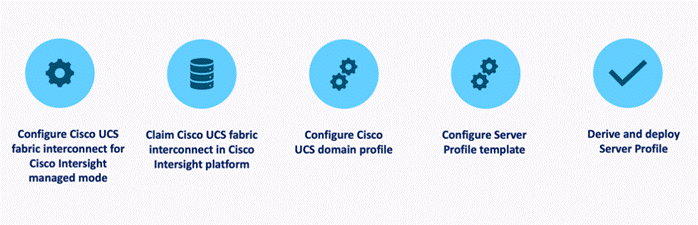
Set Up Cisco UCS Fabric Interconnect for Cisco Intersight Managed Mode
During the initial configuration, for the management mode the configuration wizard enables customers to choose whether to manage the fabric interconnect through Cisco UCS Manager or the Cisco Intersight platform. Customers can switch the management mode for the fabric interconnects between Cisco Intersight and Cisco UCS Manager at any time; however, Cisco UCS FIs must be set up in Intersight Managed Mode (IMM) for configuring the Cisco UCS X-Series system. Figure 52 shows the dialog during initial configuration of Cisco UCS FIs for setting up IMM.
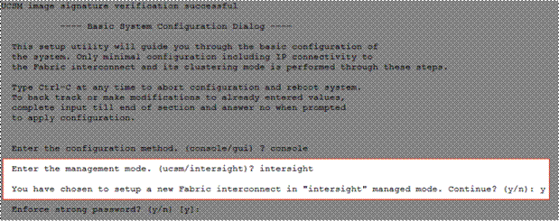
Claim a Cisco UCS Fabric Interconnect in the Cisco Intersight Platform
After setting up the Cisco UCS 6454 Fabric Interconnect for Cisco Intersight Managed Mode, FIs can be claimed to a new or an existing Cisco Intersight account. When a Cisco UCS Fabric Interconnect is successfully added to Cisco Intersight, all future configuration steps are completed in the Cisco Intersight portal.
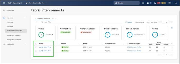
You can verify whether a Cisco UCS Fabric Interconnect is in Cisco UCS Manager managed mode or Cisco Intersight Managed Mode by clicking on the fabric interconnect name and looking at the detailed information screen for the FI, as shown in Figure 54.
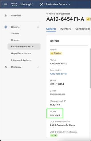
Cisco UCS Chassis Profile
A Cisco UCS Chassis profile configures and associates the chassis policy to a Cisco UCS chassis. The chassis profile feature is available in Intersight only if customers have installed the Intersight Essentials License. The chassis-related policies can be attached to the profile either at the time of creation or later.
The chassis profile in a FlashStack is used to set the power policy for the chassis. By default, Cisco UCS X-Series power supplies are configured in GRID mode, but power policy can be utilized to set the power supplies in non-redundant or N+1/N+2 redundant modes.
Cisco UCS Domain Profile
A Cisco UCS domain profile configures a fabric interconnect pair through reusable policies, allows configuration of the ports and port channels, and configures the VLANs and VSANs to be used in the network. It defines the characteristics of and configures the ports on the fabric interconnects. One Cisco UCS domain profile can be assigned to one fabric interconnect domain.
Some of the characteristics of the Cisco UCS domain profile in the FlashStack environment are:
● A single domain profile is created for the pair of Cisco UCS fabric interconnects.
● Unique port policies are defined for the two fabric interconnects.
● The VLAN configuration policy is common to the fabric interconnect pair because both fabric interconnects are configured for the same set of VLANs.
● The VSAN configuration policies (FC connectivity option) are unique for the two fabric interconnects because the VSANs are unique.
● The Network Time Protocol (NTP), network connectivity, and system Quality-of-Service (QoS) policies are common to the fabric interconnect pair.
After the Cisco UCS domain profile has been successfully created and deployed, the policies including the port policies are pushed to Cisco UCS Fabric Interconnects. Cisco UCS domain profile can easily be cloned to install additional Cisco UCS systems. When cloning the UCS domain profile, the new UCS domains utilize the existing policies for consistent deployment of additional Cisco UCS systems at scale.
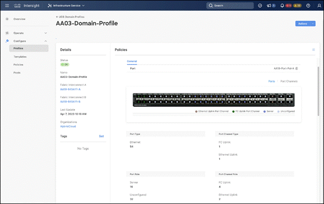
The Cisco UCS X9508 Chassis and Cisco UCS X210c M7 Compute Nodes are automatically discovered when the ports are successfully configured using the domain profile as shown in the following figures:
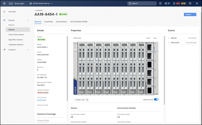
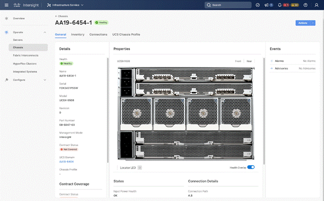
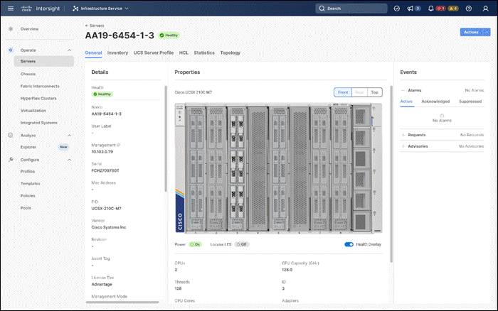
Server Profile Template
A server profile template enables resource management by simplifying policy alignment and server configuration. A server profile template is created using the server profile template wizard. The server profile template wizard groups the server policies into the following four categories to provide a quick summary view of the policies that are attached to a profile:
● Compute policies: BIOS, boot order, and virtual media policies.
● Network policies: adapter configuration, LAN connectivity, and SAN connectivity policies.
◦ The LAN connectivity policy requires you to create Ethernet network policy, Ethernet adapter policy, and Ethernet QoS policy.
◦ The SAN connectivity policy requires you to create Fibre Channel (FC) network policy, Fibre Channel adapter policy, and Fibre Channel QoS policy. SAN connectivity policy is only required for the FC connectivity option.
● Storage policies configure local storage and are not used in FlashStack.
● Management policies: device connector, Intelligent Platform Management Interface (IPMI) over LAN, Lightweight Directory Access Protocol (LDAP), local user, network connectivity, Simple Mail Transfer Protocol (SMTP), Simple Network Management Protocol (SNMP), Secure Shell (SSH), Serial over LAN (SOL), syslog, and virtual Keyboard, Video, and Mouse (KVM) policies
Some of the characteristics of the server profile template for FlashStack are:
● BIOS policy is created to specify various server parameters in accordance with FlashStack best practices.
● Boot order policy defines virtual media (KVM mapper DVD), all SAN paths for Pure Storage FlashArray (iSCSI or Fibre Channel interfaces), and UEFI Shell.
● IMC access policy defines the management IP address pool for KVM access.
● Local user policy is used to enable KVM-based user access.
● For the iSCSI boot from SAN configuration, LAN connectivity policy is used to create eight virtual network interface cards (vNICs) — two for management virtual switch (vSwitch0), two for OpenShift Container Platform data, two for application Virtual Distributed Switch (VDS), and one each for iSCSI A/B vSwitches. Various policies and pools are also created for the vNIC configuration.
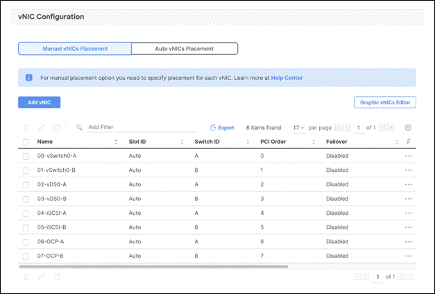
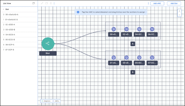
● 5th Generation Cisco UCS VICs supports up to 16384 Receive and Transmit ring sizes. Therefore, the Ethernet Adapter policy can be configured accordingly while creating iSCSI vNICS for optimized performance. Multiple receive queues along with enabling receive side scaling (RSS) allows parallel processing of network packets.
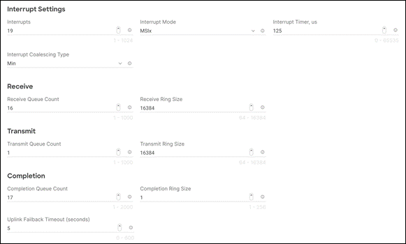
● For the FC boot from SAN configuration, LAN connectivity policy is used to create six vNICs — two for management virtual switches (vSwitch0), two for OpenShift Container Platform data and two for application VDS — along with various policies and pools.
● For the FC connectivity option, SAN connectivity policy is used to create four virtual host bus adapters (vHBAs) — along with various policies and pools. 2 vHBAs (vHBA-A and vHBA-B) are of vHBA type “fc-inititator” and 2 vHBAs (vHBA-NVMe-A and vHBA-NVMe-B) are of vHBA type “fc-nvme-initiator”. The SAN connectivity policy is not required for iSCSI setup.
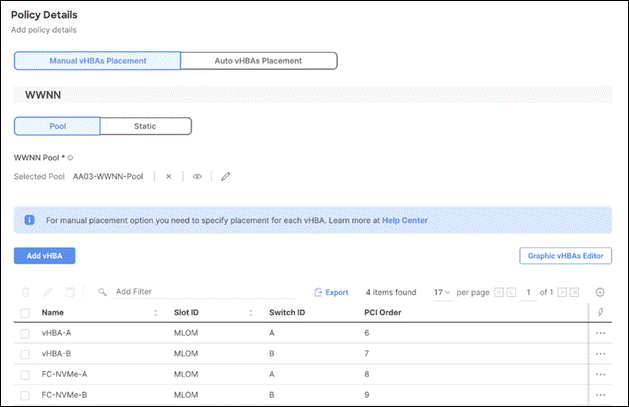
Figure 63 shows various policies associated with the server profile template.
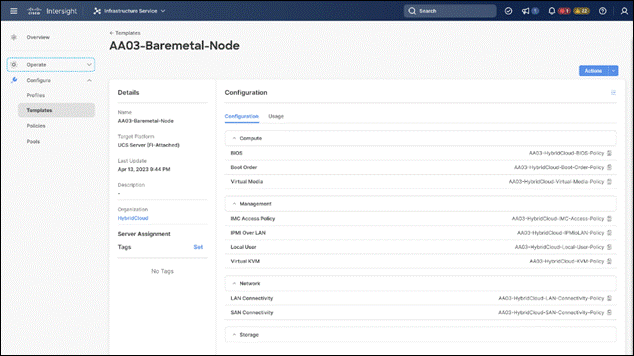
Multiple vNICs (and vHBAs) are created for the ESXi hosts using the Cisco Intersight server profile and are then assigned to specific virtual and distributed switches. The vNIC and (optional) vHBA distribution for the ESXi hosts is as follows:
● Two vNICs (one on each fabric) for vSwitch0 to support core services such as management traffic.
● Two vNICs (one on each fabric) for OCP-Data vSwitch for OpenShift Container Platform data traffic.
● Two vNICs (one on each fabric) for vSphere Virtual Distributed Switch (VDS) to support customer data traffic and vMotion traffic.
● One vNIC each for Fabric-A and Fabric-B for iSCSI stateless boot. These vNICs are only required when iSCSI boot from SAN configuration is desired.
● One vHBA each for Fabric-A and Fabric-B for FC stateless boot. These vHBAs are only required when FC connectivity is desired.
The following figures illustrate how the ESXi vNIC configurations in detail:
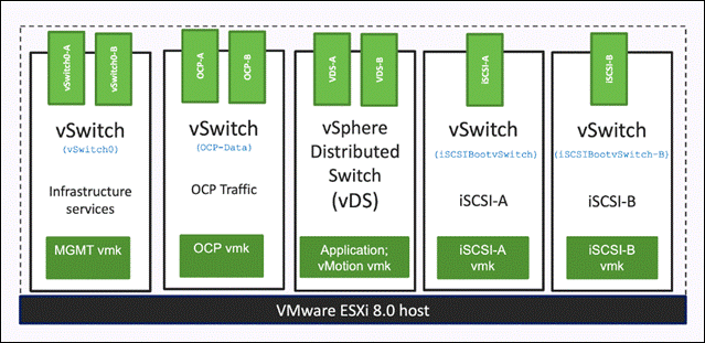
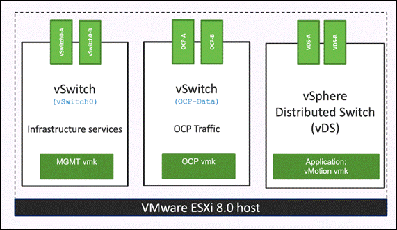
Pure Storage FlashArray – Storage Design
To set up Pure Storage FlashArray you must configure the following items:
● Volumes
◦ ESXi boot LUNs: These LUNs enable ESXi host boot from SAN functionality using iSCSI or Fibre Channel.
◦ The vSphere environment: vSphere uses the infrastructure datastore(s) to store the virtual machines.
● Hosts
◦ All FlashArray ESXi hosts are defined.
◦ Add every active initiator for a given ESXi host.
● Host groups
◦ All ESXi hosts in a VMware cluster are part of the host group.
◦ Host groups are used to mount VM infrastructure datastores in the VMware environment.
The volumes, interfaces, and VLAN/VSAN details are shown in the following figures for iSCSI and Fibre Channel connectivity, respectively.
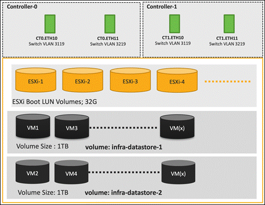
Along with SCSI-FC, solution also implements NVMe using the FC-NVMe protocol over a SAN built using Cisco MDS switches. NVMe initiators consisting of Cisco UCS X210C servers installed with Cisco VIC adapters can access Pure FlashArray NVMe targets over Fibre Channel.
Each port on the Pure FlashArray can be configured as traditional scsi-fc port or as a nvme-fc port to support NVMe end-to-end via fibre channel from the host to storage array. Note that a given FC port is either going to be SCSI or NVMe on the FlashArray.
Two ports on each Pure FlashArray controllers are configured as SCSI ports and the other two are configured as NVMe ports in this design validation as shown in Figure 67.
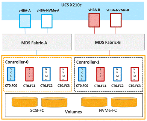
Cisco UCS provides a unified fabric that is an architectural approach delivering flexibility, scalability, intelligence, and simplicity. This flexibility allows Cisco UCS to readily support new technologies such as FC-NVMe seamlessly. In a Cisco UCS service profile, both standard Fibre Channel and FC-NVMe vHBAs can be created.
Both Fibre Channel and FC-NVMe vHBAs can exist in a Cisco UCS service profile on a single server. In the lab validation for this document, four vHBAs (one FC-NVME initiator on each Fibre Channel fabric and one Fibre Channel initiator on each Fibre Channel fabric) were created in each service profile. Each vHBA, regardless of type, was automatically assigned a worldwide node name (WWNN) and a worldwide port name (WWPN). The Cisco UCS fabric interconnects were in Fibre Channel end-host mode (NPV mode) and uplinked through a SAN port channel to the Cisco MDS 9132T switches in NPV mode. Zoning in the Cisco MDS 9132T switches connected the vHBAs to storage targets for both FC-NVMe and Fibre Channel. Single-initiator, multiple-target zones were used for both FCP and FC-NVMe.
The ESXi automatically connects to Pure FlashArray NVMe subsystem and discovers all shared NVMe storage devices that it can reach once the SAN zoning on MDS switches, and the configuration of host/host groups and volumes is completed on the Pure FlashArray.
Pure Storage FlashArray Considerations
Connectivity
● Each FlashArray Controller should be connected to BOTH storage fabrics (A/B).
● Make sure to include I/O Cards which supports 25 GE are installed in original FlashArray BOM
● Pure Storage offers up to 32Gb FC support on the FlashArray//X and 64Gb FC on the latest FlashArray//XL series arrays. Always make sure the correct number of HBAs and SFPs (with appropriate speed) are included in the original FlashArray BOM.
● For NVME-FC, make sure to include the I/O controller interfaces with service “Nvme-fc.”
Host Groups and Volumes
It is a best practice to map Hosts to Host Groups and the Host Groups to Volumes in Purity. This ensures the Volume is presented on the same LUN ID to all hosts and allows for simplified management of ESXi Clusters across multiple nodes.
Size of the Volume
Purity removes the complexities of aggregates and RAID groups. When managing storage, a volume should be created based on the size required and purity takes care of availability and performance via RAID-HD and DirectFlash software. You can create 1 10-TB volume or 10 1-TB volumes and the performance and availability for these volumes will always be consistent. This feature allows you to focus on recoverability, manageability, and administrative considerations of volumes instead of dwelling on availability or performance.
vCenter Deployment Consideration
While hosting the vCenter on the same ESXi hosts that the vCenter will manage is supported, it is a best practice to deploy the vCenter on a separate management infrastructure. The ESXi hosts in this new FlashStack with Cisco UCS X-Series environment can also be added to an existing customer vCenter. The in-band management VLAN will provide connectivity between the vCenter and the ESXi hosts deployed in the new FlashStack environment.
An MTU of 9216 is configured at all network levels to allow jumbo frames as needed by the guest OS and application layer. The MTU value of 9000 is used on all the vSwitches and vSphere Distributed Switches (VDS) in the VMware environment.
Boot From SAN
When utilizing Cisco UCS Server technology with shared storage, it is recommended to configure boot from SAN and store the boot LUNs on remote storage. This enables architects and administrators to take full advantage of the stateless nature of Cisco UCS X-Series Server Profiles for hardware flexibility across the server hardware and overall portability of server identity. Boot from SAN also removes the need to populate local server storage thereby reducing cost and administrative overhead.
UEFI Boot
This validation of FlashStack uses Unified Extensible Firmware Interface (UEFI). UEFI is a specification that defines a software interface between an operating system and platform firmware.
NVMe over Fabrics
NVMe over Fabrics (NVMe-oF) is an extension of the NVMe network protocol to Ethernet and Fibre Channel delivering faster and more efficient connectivity between storage and servers as well as a reduction in CPU utilization of application host servers. This validation of FlashStack supports NVMe over Fibre Channel (NVMe/FC) to provide the high-performance and low-latency benefits of NVMe across fabrics. In this solution, NVMe initiators consisting of Cisco UCS X210c compute nodes access Pure FlashArray NVMe targets over Fibre Channel.
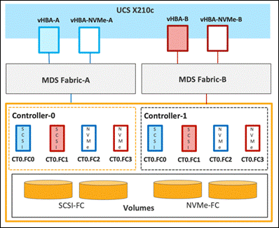
Each port on the Pure FlashArray can be configured as traditional scsi-fc port or as a nvme-fc port to support NVMe end-to-end via fibre channel from the host to storage array. Two ports on each Pure Storage FlashArray controller are configured as SCSI ports and two ports are configured as NVMe ports as shown in Figure 68.
Note: A given FC port on Pure Storage FlashArray can either be configured as FC-SCSI or FC-NVMe port.
In a Cisco UCS server profile, both standard Fibre Channel and FC-NVMe vHBAs can be created. A default Fibre Channel adapter policy named fc-nvme-initiator is preconfigured in Cisco Intersight. This policy contains recommended adapter settings for FC-NVMe, including 16 I/O queues allowing parallel processing of NVMe packets. Both Fibre Channel and FC-NVMe vHBAs can exist in a Cisco UCS server profile on a single server.
To support NVMe over Fabric, four vHBAs, two FC-NVME initiators and two Fibre Channel initiators (one on each Fibre Channel fabric), are created for each server profile. Cisco MDS 9132T switches are configured with appropriate zoning to connect the FC-NVMe and Fibre Channel vHBAs to appropriate storage targets. Single-initiator, multiple-target zones are used for both FCP and FC-NVMe. VMware ESXi automatically connects to Pure FlashArray NVMe subsystem and discovers all shared NVMe storage devices that it can reach once the SAN zoning on MDS switches, and the configuration of host/host groups and volumes is completed on the Pure FlashArray.
Pure Storage FlashBlade – Storage Design
To set up Pure Storage FlashBlade you must configure the following items:
● NFS: A single or multiple NFS volume with export rules for appropriate permissions.
● Configured NFS data services by choosing the interfaces in each FIOM and configured LAGs, IP address, subnet and VLAN details in the FlashBlade.
● Configure connection, protocol information and NFS versions v3 or v4.1.
● In the Portworx specify mount options through the CSI mountOptions flag in the storageClass spec.
● Create PVC by referencing the StorageClass that was created and enter the StorageClass name in the spec.storageClassName field.
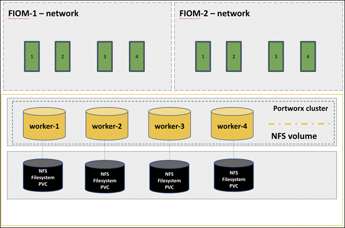
Cisco Intersight Integration with FlashStack
Cisco Intersight enhances the ability to provide complete visibility, orchestration, and optimization across all elements of FlashStack datacenter. This empowers customers to make intelligent deployment decisions, easy management, optimize cost and performance and maintain supported configurations for their infrastructure.
Cisco Intersight works with Pure Storage FlashArray, VMware vCenter using third-party device connectors. Since third-party infrastructure does not contain any built-in Intersight device connector, Cisco Intersight Assist virtual appliance enables Cisco Intersight to communicate with these non-Cisco devices. Also, Physical, and logical inventories of Ethernet and Storage area networks are available within Intersight.
Note: A single Cisco Intersight Assist virtual appliance can support both Pure Storage FlashArray and VMware vCenter.
Cisco Intersight integration with VMware vCenter, Pure Storage FlashArrays, Nexus and MDS switches enables customers to perform following tasks right from the Intersight dashboard:
● Monitor the virtualization of storage and network environment.
● Add various dashboard widgets to obtain useful at-a-glance information.
● Perform common Virtual Machine tasks such as power on/off, remote console and so on.
● Orchestration of Virtual, Storage and network environment to perform common configuration tasks.
● Extend optimization capability for entire FlashStack datacenter.
The following sections explain the details of these operations. Since Cisco Intersight is a SaaS platform, the monitoring and orchestration capabilities are constantly being added and delivered seamlessly from the cloud.
Note: The monitoring capabilities and orchestration tasks and workflows listed below provide an in-time snapshot for your reference. For the most up to date list of capabilities and features, you should use the help and search capabilities in Cisco Intersight.
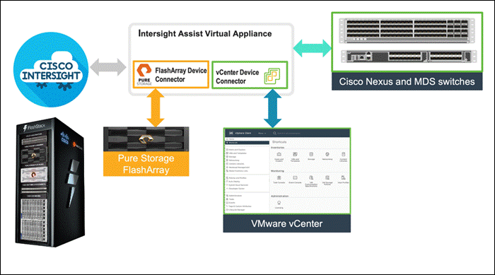
Integrate Cisco Intersight with Pure Storage FlashArray
To integrate Pure Storage FlashArray with the Cisco Intersight platform, you must deploy a Cisco Intersight Assist virtual appliance and claim Pure Storage FlashArray as a target in the Cisco Intersight application, as shown in Figure 71.
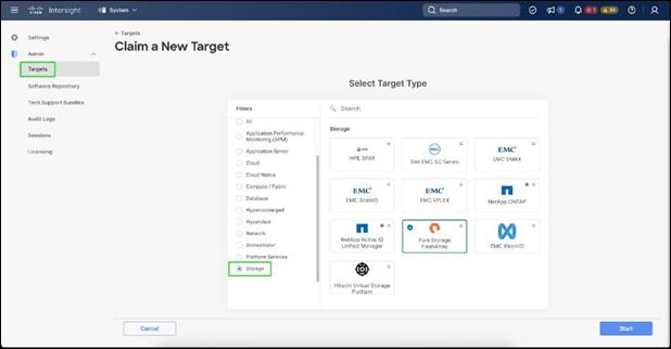
After successfully claiming Pure Storage FlashArray as a target, you can view storage-level information in Cisco Intersight.
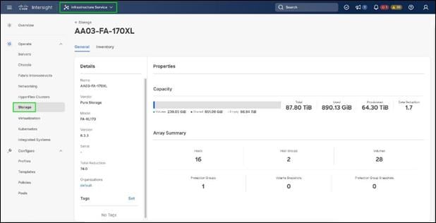
Cisco Intersight Cloud Orchestrator provides various workflows that can be used to automate storage provisioning. Some of the storage workflows available for Pure Storage FlashArray are listed in Figure 73.
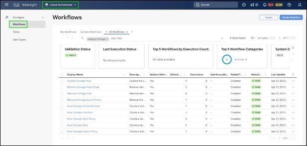
Integrate Cisco Intersight with VMware vCenter
To integrate VMware vCenter with Cisco Intersight, VMware vCenter can be claimed as a target using Cisco Intersight Assist Virtual Appliance, as shown in Figure 74.
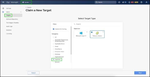
After successfully claiming the VMware vCenter as a target, you can view hypervisor-level information in Cisco Intersight including hosts, VMs, clusters, datastores, and so on.
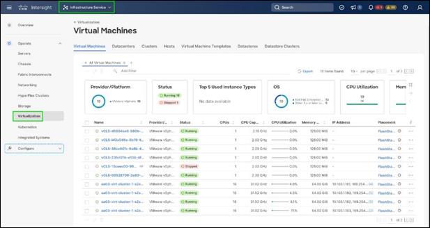
VMware vCenter integration with Cisco Intersight allows you to directly interact with the virtual machines (VMs) from the Cisco Intersight dashboard. In addition to obtaining in-depth information about a VM, including the operating system, CPU, memory, host name, and IP addresses assigned to the virtual machines, you can use Intersight to perform various actions.
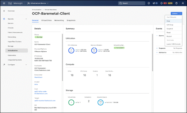
Cisco Intersight Cloud Orchestrator provides various workflows that can be used for the VM and hypervisor provisioning.
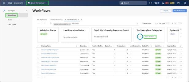
Integrate Cisco Intersight with Nexus and MDS Switches
To integrate Cisco Nexus and MDS switches with Cisco Intersight, Cisco Nexus and MDS switches can be claimed as a target using Cisco Intersight Assist Virtual Appliance deployed earlier.
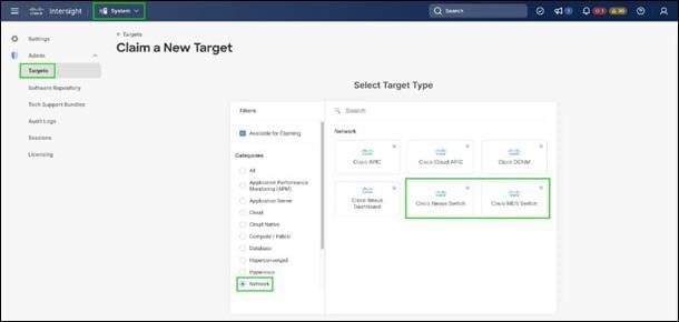
After successfully claiming the Cisco Nexus and MDS switches as targets, you can view their Ethernet and SAN details in Cisco Intersight including Physical and logical inventory.
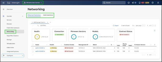
Red Hat OpenShift Container Platform On-Premises
Some of the attributes of Red Hat OpenShift Container Platform on-premises are:
● OpenShift can run on-premises either on a virtualization layer or directly on bare metal. Integration with bare metal includes use of Redfish Virtual Media and/or IPMI to directly control local servers through their baseboard management controllers. OpenShift uses the Metal3 project for Kubernetes-native bare metal management.
● A typical highly-available OpenShift cluster will have three control plane nodes and two or more worker nodes. For a smaller HA footprint, three nodes can each act as part of the control plane and also accept workloads.
● OpenShift includes a rich set of observability features. Metrics, logs, and alerts can be viewed and consumed with built-in features and tools, and they can also be published to a variety of third-party systems.
● On-premises infrastructure is sometimes disconnected or air-gapped for security purposes. OpenShift offers a complete first-class experience for securely deploying clusters and delivering updates to all layers of the cluster infrastructure, including the operating system, core Kubernetes, additional Kubernetes-related components (observability, storage, network management, developer workflows, and so on), management tooling, and optional Kubernetes Operators.
● The systems underlying each node can be optimized using the Node Tuning Operator. The TuneD daemon is used in a similar manner as with Red Hat Enterprise Linux; a performance profile is either created or selected from the list of built-in profiles, and then the TuneD daemon uses that profile on each system to configure kernel features such as CPU assignments and the low-latency and determinism of the realtime kernel.
● Each OpenShift release includes a specific version of RHEL CoreOS and all of the OpenShift components. There is no need to provision and maintain a base operating system, because OpenShift includes the OS in its installation and ongoing management.
● OpenShift Virtualization is an add-on to OpenShift Container Platform that enables virtual machines to be run and managed in Pods alongside containerized workloads. Kubernetes-native APIs enable virtual machines to be created, managed, imported, cloned, and live-migrated to other nodes.
Red Hat OpenShift Service on AWS
● ROSA provides a fully-managed application platform that is seamlessly integrated with AWS services and backed by a global team of SREs.
● ROSA is deployed and billed directly through an AWS account.
● A ROSA cluster can optionally be deployed across multiple availability zones, which enhances the opportunity for the cluster and its workloads to remain highly available through an infrastructure disruption. Best practices should still be followed for application high availability, such as the use of Pod Disruption Budgets, which help keep a service running through voluntary / expected disruption (such as nodes upgrading in-place during a cluster upgrade).
● ROSA has a variety of industry standard security and control certifications, including HIPAA and PCI DSS. A complete list is available in the documentation.
● Auto-scaling can be configured to add and remove compute nodes in a ROSA cluster based on pod scheduling pressure. A minimum and maximum number of compute nodes can be configured to ensure that a predictable footprint remains available.
● The ROSA-CLI is used to deploy Red Hat OpenShift on AWS to the AWS environment.
The OpenShift Container Platform cluster uses a virtualized network for pod and service networks. The OVN-Kubernetes Container Network Interface (CNI) plug-in is a network provider for the default cluster network. A cluster that uses the OVN-Kubernetes network provider also runs Open vSwitch (OVS) on each node. OVN configures OVS on each node to implement the declared network configuration.
The OVN-Kubernetes default Container Network Interface (CNI) network provider implements the following features:
● Uses OVN (Open Virtual Network) to manage network traffic flows. OVN is a community developed, vendor agnostic network virtualization solution.
● Implements Kubernetes network policy support, including ingress and egress rules.
● Uses the Geneve (Generic Network Virtualization Encapsulation) protocol rather than VXLAN to create an overlay network between nodes.
The internal and external OCP Virtual Networking Design is shown in Figure 80.
Control Plane nodes and worker nodes, connect to two networks; OVN-Kubernetes that OpenShift manages and then the physical datacenter network.
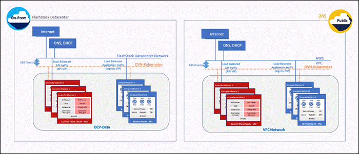
By default, Kubernetes (and OCP) allocates each pod an internal cluster-wide IP address that it can use for Pod-to-Pod communication. Within a Pod, all containers behave as if they’re on the same logical host and communicate with each other using localhost, using the ports assigned to the containers. All containers within a Pod can communicate with each other using the Pod network.
For communication outside the cluster, OCP provides services (node ports, load balancers) and API resources (Ingress, Route) to expose an application or a service outside cluster so that users can securely access the application or service running on the OCP cluster. API resources, Ingress and Routes are used in this solution to expose the application deployed in the OCP cluster.
Portworx Enterprise Kubernetes Storage Platform Design Considerations
Sizing of Disks
When sizing the disks, it is recommended to configure volumes with adequate capacity for any given workload to be deployed in the cluster. If an application requires 500GB of capacity, then configure more than 500GB per node using the configuration wizard. This could be a quantity of four 150GB EBS volumes, or one large 600GB volume.
Additionally, it is recommended to configure PX- Autopilot to protect applications from downtime related to filling the PVCs in use and the Portworx cluster.
Prerequisites for Portworx on VMware vSphere
The following are the prerequisites for Portworx on VMware vSphere:
● VMware vSphere version 7.0 or newer.
● kubectl configured on the machine having access to the cluster.
● Portworx does not support the movement of VMDK files from the datastores on which they were created.
● Cluster must be running OpenShift 4 or higher and the infrastructure that meets the minimum requirements for Portworx.
● Virtual Machines used for OpenShift nodes for Portworx have Secure Boot disabled.
For more information, see: https://docs.portworx.com/install-portworx/prerequisites/
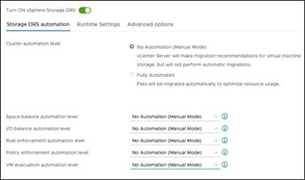
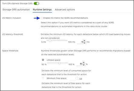
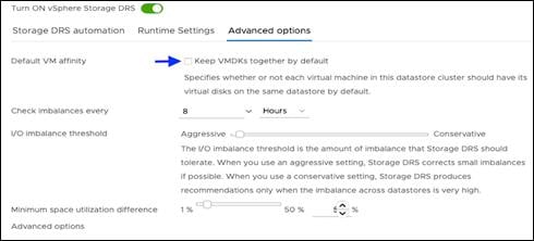
vCenter Environment Variables and User Privileges for Portworx
The following are the variables and user privileges for Portworx:
● A Kubernetes secret with vCenter User and password.
● Generate a spec of vSphere environment variables like hostname of vCenter, port number, datastore prefix and other variables.
● Generate and apply a spec file.
● Administrator has to create a disk template which Portworx will use the disk template as a reference for creating disks, virtual volumes for PVCs.
Table 6. vCenter User privileges
|
|
|
|
| Allocate space |
Local operations |
Change Configuration |
| Browse datastore |
Reconfigure virtual machine |
Add existing disk |
| Low level file operations |
|
Add new disk |
| Remove file |
Add or remove device |
|
|
|
Advanced configuration |
|
| Change Settings |
||
| Extend virtual disk |
||
| Modify device settings |
||
| Remove disk |
Note: If you create a custom role as shown above, make sure to select “Propagate to children” when assigning the user to the role.
Disk Provisioning of Portworx on VMware vSphere
When provisioning Portworx on VMware vSphere, the following occurs:
● Pure Storage FlashArray XL provides block storage (vVOLs, FC and iSCSI) to ESXi hypervisors.
● VMware vSphere datastores are created on the vCenter and Users can create a vSphere datastore cluster.
● vSphere datastore clusters are accessed by Portworx storage.
● Portworx runs on each Kubernetes worker Node and on each node will create its disk on the configured shared datastores or datastore clusters.
● Portworx will aggregate all of the disks and form a single storage cluster. Administrators can carve PVCs (Persistent Volume Claims), PVs (Persistent Volumes) and Snapshots from this storage cluster.
● Portworx tracks and manages the disks that it creates. In a failure event, if a new VM spins up, then the new VM will be able to attach to the same disk that was previously created by the node on the failed VM.
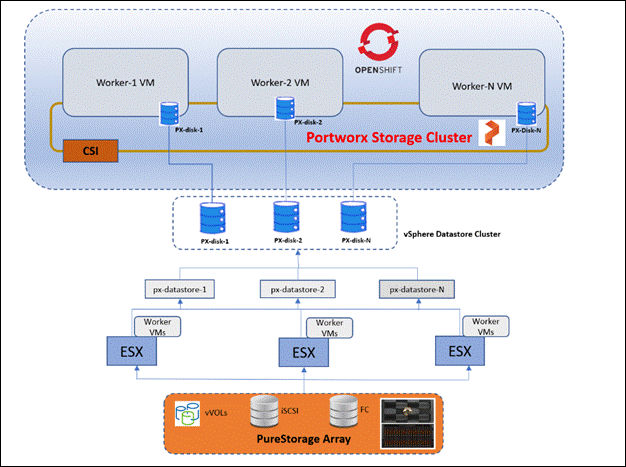
FlashBlade Direct Access filesystem on Portworx
The FlashBlade Direct Access filesystem on Portworx does the following:
§ Pure Storage FlashBlade with Portworx on OpenShift can attach FlashBlade as a Direct Access filesystem.
§ Portworx directly provisions FlashBlade NFS filesystems, maps them to a user PVC, and mounts them to pods.
§ FlashBlade Direct Access filesystems supports basic filesystem operations: create, mount, expand, unmount, delete. NFS control rules for each Nodes.
§ Portworx runs on each Kubernetes worker Node and on each node will create its disk on the configured shared datastores or datastore clusters.
§ Direct Access dynamically creates filesystems on FlashBlade that are managed by Portworx on demand.
§ Portworx provisions an NFS filesystem on FlashBlade and maps it directly to that PVC based on configuration information provided in the storageClass spec.
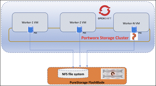
Figure 86 illustrates the Portworx CSI architecture.
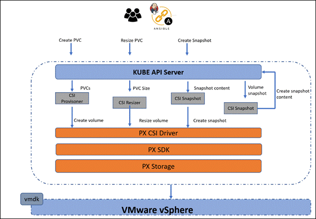
● Portworx provides dynamic disk provisioning on the OpenShift Container Platform running on VMware vSphere.
● Portworx includes a number of default StorageClasses, which can reference with PersistentVolumeClaims (PVCs).
● Portworx CSI driver is API layer in-between the Kubernetes and Portworx SDK.
● Portworx SDK uses either the default gRPC port 9020 or the default REST Gateway port 9021.
● OpenStorage SDK can be plugged into CSI Kubernetes and Docker volumes.
● PX-Storage provides cloud native storage for application running in the cloud, on-prem or hybrid platforms.
● Here PX-Storage communicates with the VMware vSphere vmdk to process the requests.
● Portworx supports:
◦ Provision, attach and mount volumes
◦ CSI snapshots
◦ Stork
◦ Volume expansion or resizing
Solution Validation
This chapter contains the following:
● Inferencing Software Components
● Infrastructure and Cluster Setup for Validation
● Hardware and Software Matrix
● Model Deployment on Triton Inference Server
● Model Deployment using Hugging Face Text Generation Inference
This Cisco Validated Design for FlashStack for Generative AI Inferencing offers a comprehensive platform for AI architects and practitioners to deploy generative AI models quickly and efficiently for intelligent enterprise applications ensuring monitoring, visibility, operational simplicity, and ease.
This CVD describes a spectrum of generative AI models, along with inferencing servers and backends deployed on the Red Hat OpenShift on the virtualized infrastructure.
Table 7 lists the Generative AI models that were validated.
Table 7. OpenShift Environment Configuration where Models are Deployed
| Inference Serving |
Model |
Container Used for Inferencing |
| NeMo Framework Inference
|
GPT 2B Nemotron-GPT 8B Llama 7B (Converted to NeMo) Llama 13B (Converted to NeMo) |
nvcr.io/ea-bignlp/ga-participants/nemofw-inference:23.10
|
| Text Generation Inference (TGI) |
BLOOM 7B Google FLAN-T5 XL 2.85B Google FLAN-T5 XXL 11.3B GALACTICA 30 B GPT-NeoX-20B OPT- 2.7B MPT-30B Falcon-40B Mistral-7B-v0.1 Code Llama 34B-Base Code Llama 34B-Python Defog SQLCoder-15B Defog SQLCoder-34B |
ghcr.io/huggingface/text-generation-inference
|
| Pytorch |
Llama 2 7B Llama 2 13B |
nvcr.io/nvidia/pytorch:23.09-py3 |
| Python |
Stable Diffusion 2.0 Openjourney Dreamlike Diffusion 1.0 Hotshot-XL |
Python:latest |
Inferencing Software Components
Generative AI models were validated using NVIDIA Triton Inference Server and Hugging Face Text Generation Inference. Inferencing was also run on Python and PyTorch containers from NVIDIA NGC.
Triton Inference Server
The GPT models were deployed using the Triton Inference server with NVIDIA TensorRT-LLM model Optimizer. Llama models converted to NeMo format were also validated with Triton Inference server with NVIDIA TensorRT-LLM model Optimizer.
The TensorRT-LLM model Optimizer is new and performs better compared to FasterTransformer (FT) backend. TensorRT-LLM and Triton inference server are integrated into Nemo inference container which is part of Nemo framework.
NeMo Framework Inference Container contains modules and scripts to help exporting nemo LLM models to TensorRT-LLM and deploying nemo LLM models to Triton Inference Server with easy-to-use APIs.
NVIDIA TensorRT, NVIDIA TensorRT-LLM, NVIDIA Triton Inference Server, are part of NVIDIA AI Enterprise.
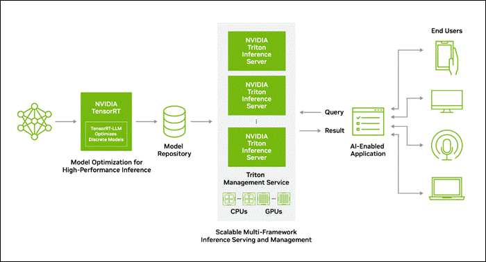
Table 8 lists the supported models with a different number of parameters in distributed NeMo checkpoint format.
Table 8. Supported models with NeMo Framework Inference Container
| Model Name |
Model Parameters |
NeMo Precision |
TensorRT-LLM Precision |
Fine Tuning |
| GPT |
2B, 8B |
bfloat16 |
bfloat16 |
SFT, RLHF, SteerLM |
| LLAMA2 |
7B, 13B |
bfloat16 |
bfloat16 |
SFT, RLHF, SteerLM |
Text Generation Inference
BLOOM, Google FLAN-T5, GALACTICA, GPT-NeoX, OPT, MOT, Falcon, Mistral, and Code Llama were deployed with Hugging Face Text Generation Inference(TGI). TGI enables high-performance text generation for these models.
Pytorch
We also wanted to demonstrate how a regular Pytorch container can be used for inferencing. Hence, we validated Llama models with Pytorch as well along with Triton Inference server.
Python
Python container image is used to deploy and evaluate non LLM models like Stable Diffusion, Openjourney and Dreamlike Diffusion 1.0
Infrastructure and Cluster Setup for Validation
The inferencing solution is deployed on FlashStack Datacenter.
2 X Cisco UCS X210c M7 Compute Nodes are mapped with Cisco UCS X440p PCle Node to install GPUs. One X440p PCle Node is installed with 2 X A100 GPU and other with 2 X L40 GPUs, VMware vSphere 8.0 cluster is formed with Cisco UCS X210c M7 Compute Nodes. NVIDIA AI Enterprise Host Software is installed on the host server with NVIDIA GPUs installed.
Red Hat OpenShift is installed on VMware vSphere 8.0 cluster. Control plane and worker nodes are running as virtual machines on VMware vSphere 8.0 cluster. One of the worker node is added with 2 X A100 Virtual GPUs and other with 2 L40 Virtual GPUs.
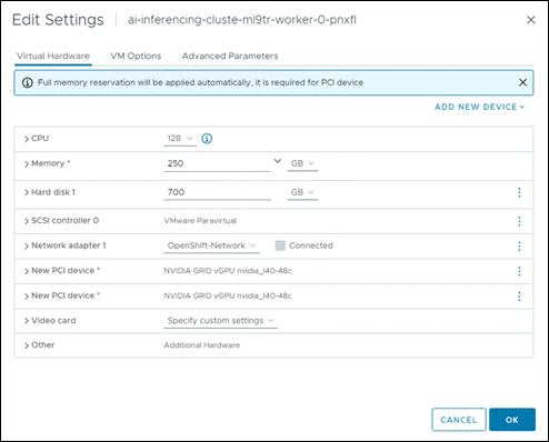
NVIDIA GPU Operator is configured in the Red Hat OpenShift environment. The NVIDIA GPU Operator allows DevOps Engineers of Kubernetes clusters to manage GPU nodes just like CPU nodes in the cluster. It installs and manages the lifecycle of software components so GPU accelerated applications can be run on Kubernetes.
Portworx Enterprise backed by Pure Storage Flash Array and Pure Storage FlashBlade with NFS target are configured for model repository.
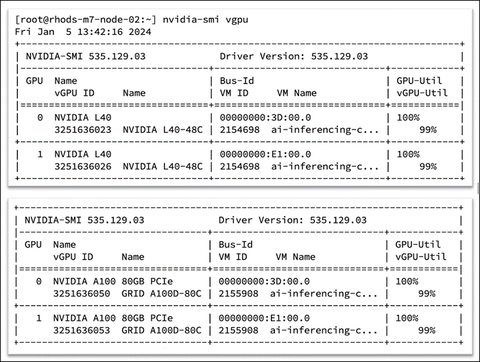
Cluster Setup
OpenShift Cluster deployed on VMware vSphere.(Installer-provisioned infrastructure). Installation is CLI based using an install program(openshift-install). To initiate the install, it’s required to prepare a install-config.yaml configuration file. A sample file is provided below:
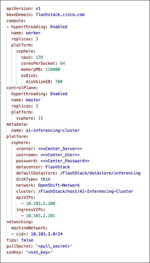
Worker Node Configuration
Control plane nodes were created with default configuration. (Resources - 4 CPUs, 16 GB Memory and 120 GB Hard Disk). The following are the resources assigned to the worker nodes:
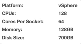
Table 9 lists the required hardware components used to build the validated solution. You are encouraged to review your requirements and adjust the size or quantity of various components as needed.
Table 9. FlashStack Datacenter with Red Hat OCP Hardware Components
| Component |
Hardware |
Comments |
| Fabric Interconnects |
Two Cisco UCS Fabric Interconnects such as Cisco UCS 6454 FI |
FI generation dependent on the speed requirement. 4th Generation supports 25Gbps and 5th Generation supports 100Gbps end-to-end. |
| Pure Storage FlashArray |
Pure Storage FlashArray storage with appropriate capacity and network connectivity such as FlashArray//XL170 |
Customer requirements will determine the amount of storage. The FlashArray should support both 25Gbps or 100 Gbps ethernet and 32Gbps FC connectivity |
| Pure Storage FlashBlade |
Pure Storage FlashBlade storage with appropriate capacity and network connectivity such as FlashBlade//S200 |
FlashBlade exposes NFS and s3 targets. It can be used as model repository. The FlashBlade should support 100 Gbps ethernet. |
| Cisco Nexus Switches |
Two Cisco Nexus 93000 series switches such as Cisco Nexus 93360YC-FX2 |
The switch model is dependent on the number of ports and the port speed required for the planned installation. |
| Cisco MDS Switches |
Two Cisco MDS 9100 series switches, i.e., MDS 9132T |
The supported port speed of the selected MDS switch must match the port speed of the Fabric Interconnect and the FlashArray. |
| Management Cluster Compute |
||
| Cisco UCS Servers
|
A minimum of two Cisco UCS servers to host management components like Intersight Assist, DHCP, DNS, Active Directory etc
|
To reduce the number of physical servers the use of a supported virtualization software like VMware ESXi is recommended.
|
| Red Hat OCP Compute |
||
| Cisco UCS Chassis |
A minimum of one UCS X9508 chassis |
Single chassis can host up to 8 Cisco UCS X210c compute nodes |
| Cisco UCS Compute Nodes |
Cisco UCS X210c M7compute nodes dependent on the workload planned on the cluster. |
|
Table 10 lists the software releases used in the solution. Device drivers, software tools and Cisco Intersight Assist versions will be explained in the deployment guide.
| Component |
Software Version |
||
| Network |
Cisco Nexus9000 C93360YC-FX2 |
10.2(3) |
|
| Cisco MDS 9132T |
8.4(2c) |
||
| GPUs |
UCSC-GPU-A100-80 |
Firmware: 95.02.5D.00.01-G133.0250.00.01 Driver: 535.129.03 |
|
| UCSC-GPU-L40 |
Firmware: 92.00.A0.00.05-1001.0230.00.03 Driver: 535.129.03 |
|
|
| Compute |
Cisco UCS Fabric Interconnect 6454 |
4.3(2.230129) |
|
| Cisco UCS UCSX 9108-25G IFM |
4.3(2b) |
||
| Cisco UCS X210C M7 Compute Nodes |
5.2(0.230092) |
||
| Cisco UCS VIC 15231 installed on X210c |
5.3(2.40) |
||
| VMware ESXi |
8.0 |
||
| Storage |
Pure Storage FlashArray//XL170 |
6.3.3 |
|
| Pure Storage FlashBlade//S200 |
4.1.12 |
||
| Pure Storage Plugin |
5.0.0 |
||
| Kubernetes |
Red Hat OpenShift Container Platform |
4.14.8 |
|
| Portworx Enterprise Kubernetes Storage Platform |
3.0 |
||
Table 11 details the configuration used in OpenShift environment where inferencing servers along with models are deployed.
Table 11. OpenShift environment configuration where models are deployed.
| Component |
|
| Platform |
VMware vSphere 8 |
| Kubernetes |
Red Hat OpenShift Container Platform 4.14.8 |
| Storage |
Portworx Enterprise 3.0 |
| GPU Operator |
NVIDIA GPU Operator 23.9.1 |
| Inference Container |
NeMo Framework Inference 23.10 |
| Worker Node configuration |
CPU – 128 vCPUs, 64 Cores per socket |
| Memory – 128 GB |
|
| Disk – 700 GB |
|
Table 12 lists the GPUs used for this validation.
Table 12. Cisco UCS and NVIDIA GPUs
|
|
NVIDIA A100 80GB PCIe GPU |
NVIDIA L40 PCIe GPU |
| Supported Cisco UCS Servers |
Cisco UCS X210c M7 Cisco UCS X410c M7 Cisco UCS X210c M6 Cisco UCS C240 M7 Cisco UCS C240 M6 Cisco UCS C240 M5 Cisco UCS C480 M5 |
Cisco UCS X210c M7 Cisco UCS X410c M7 Cisco UCS C240 M7 Cisco UCS C220 M7 |
| Cisco PID |
UCSC-GPU-A100-80 |
UCSC-GPU-L40 |
| GPU installed on |
Cisco UCS X440p PCle Node |
Cisco UCS X440p PCle Node |
| GPU Memory |
80 GB |
48 GB |
| Form Factor |
PCIe |
PCIe |
Refer to the UCS Hardware and Software Compatibility for updated information about compatible servers, firmware, drivers, and so on, here: https://ucshcltool.cloudapps.cisco.com/public/
Model Deployment on Triton Inference Server
Triton Inference Server enables multiple models and multiple instances of the same model to execute in parallel on the same system. Triton supports multiple scheduling and batching algorithms that can be selected independently of each model. Triton is tightly integrated with TensorRT-LLM for model optimization.
NeMo Framework Inference Container contains modules and scripts to help exporting nemo LLM models to TensorRT-LLM and deploying nemo LLM models to Triton Inference Server with easy-to-use APIs. This section explains how to deploy a nemo checkpoint with TensorRT-LLM.
Install using Base Container
Triton Inference server can be installed using the NeMo Framework Inference Container image and creating appropriate resources in OpenShift cluster where GPUs are exposed to the worker nodes.
A sample deployment YAML manifest is provided below:
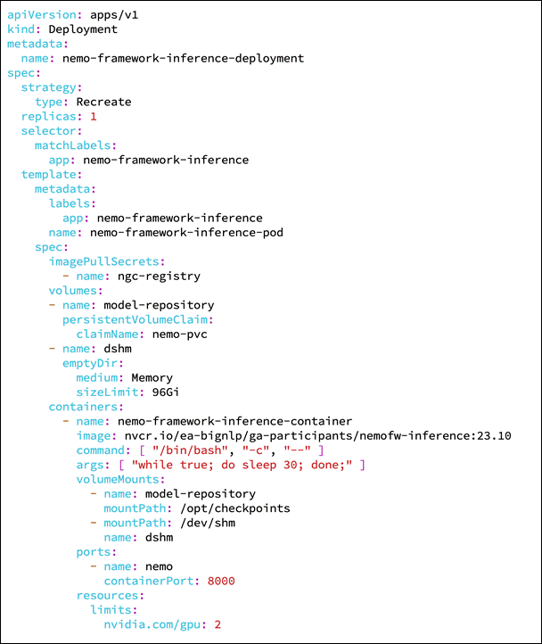
The image pull secret is required with NGC API key to download the image. It can be created using:
oc create secret docker-registry ngc-registry --docker-server=nvcr.io --docker-username=\$oauthtoken --docker-password=<API Key>
A service is required to expose the container port. A sample is provided below:
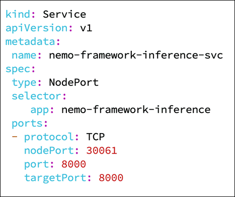
Storage
Model repository is required to store the NeMo check points and the TensorRT temp folder. This can be configured with either NFS volume from FlashBlade target or a PVC from Portworx. A sample PVC configuration is provided below:
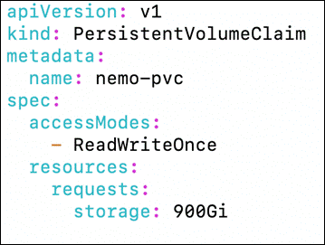
Share memory is required and therefore a volume is created in memory and mounted in /dev/shm.
Install using Helm Chart
There is also NeMo Framework Inference on Kubernetes which can be installed. Download the Helm chart from NGC with helm fetch https://helm.ngc.nvidia.com/ea-bignlp/ga-participants/charts/nemo-framework-inference-<tag>.tgz
In the Helm chat, model storage can be configured as NFS. FlashBlade can be used as NFS target.
For more information, go to: https://registry.ngc.nvidia.com/orgs/ea-bignlp/teams/ga-participants/helm-charts/nemo-framework-inference
Server Model on Triton
A LLM model in a NeMo checkpoint can be served on Triton using the following script. Script allows deployment of the models for TensorRT-LLM based inference. Once the script is executed, it will export the model to the TensorRT-LLM, and then start the service on the Triton.
Assuming the container has already been started using the steps provided, and NeMo checkpoint files are downloaded and present in “nemo_checkpoint” directory, the following script can be run to start serving the downloaded model:
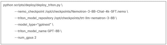
Figure 94 confirms that the NV-GPT-8B-Chat-4k-SFT is in production with Triton Inference Server with TensorRT-LLM.
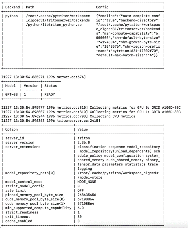
Once the service is started using the provided scripts, it will wait for any request. One way to send a query to this service is to use the NeMo classes as shown in the following example in the currently running container or in another container (and in another machine). Another way is to use PyTriton, just to send the request. Or you can make a HTTP request with different tools/libraries.
Below is a request example using NeMo APIs. You can put in a python file (or in CLI) and run:
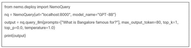
The result of sample run of above script is provided below:
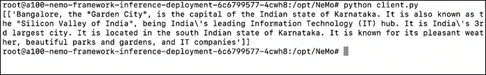
Deploy a LLM model with NeMo APIs
You can use the APIs in the deploy module to deploy a TensorRT-LLM model to Triton. A sample code is provided below:
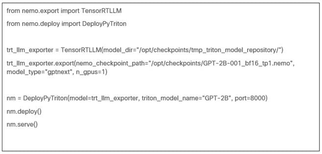
Model Deployment using Hugging Face Text Generation Inference
Text-Generation-Inference is a solution build for deploying and serving Large Language Models from Hugging Face.
Installing Text Generation Inference
Text Generation Inference can be installed using the base container image and creating appropriate resources in the OpenShift.
A sample deployment YAML manifest is provided below:
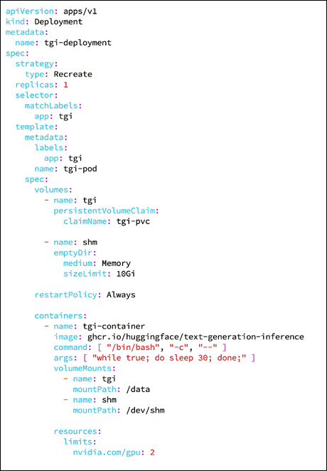
Shared memory is required to enable model sharding and therefore a volume is created and mounted in /dev/shm.
A model repository is required to store the models. All the models will in /data directory. This repository can either be a NFS volume from FlashBlade target or a PVC from Portworx. A sample PVC configuration is provided below:
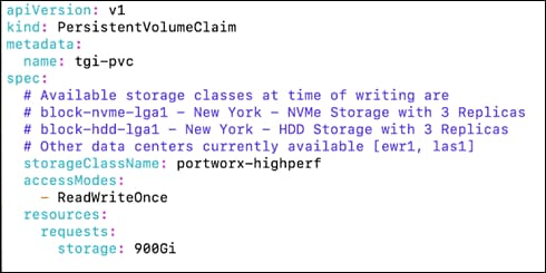
A service is required to expose the container port. A sample is provided below:
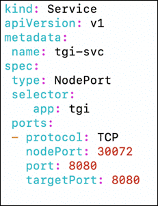
Serve Model on Text Generation Inference
A LLM model can be served on Text Generation Inference using the following script assuming the container has already been started using the provided steps.
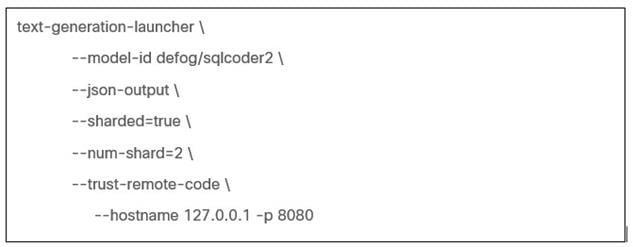
Once the service is started using the scripts above, it will wait for any request. You can send query to this service as shown below:
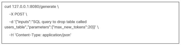
The result of a sample run of the provided script is provided below:
![]()
Inference Client
huggingface-hub is a Python library to interact with the Hugging Face Hub, including its endpoints. It provides a nice high-level class, [~huggingface_hub.InferenceClient], which makes it easy to make calls to a TGI endpoint. InferenceClient also takes care of parameter validation and provides a simple to-use interface. It is available as Python package and can be installed with pip install huggingface-hub.
Once the TGI server is started, instantiate InferenceClient() with the URL to the endpoint serving the model. Invoke text_generation() to hit the endpoint through Python. Sample code is provided below:
from huggingface_hub import InferenceClient
client = InferenceClient(model="http://127.0.0.1:8080")
client.text_generation(prompt="Write a code for snake game")
Stress Tests
This chapter discuses the stress testing performed on the infrastructure for 24 hours with 3 iterations.
2 X Cisco UCS X440p PCIe nodes are mapped to 2 X Cisco X210c M7. One X440p PCIe Node is installed with 2 X A100 GPUs and another one with 2X L40 GPUs.
2 containers are created in the OpenShift. One requesting 2 X A100 virtual GPUs and another with 2 X L40 virtual GPUs.
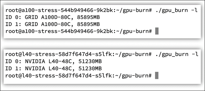
Multi-GPU CUDA stress test was on both containers for 24 hours each for 3 iterations. The stress was run using the instructions in ‘gpu-burn’ Git repo available at https://github.com/wilicc/gpu-burn
When the stress tests were started, power drawn was around 40W for L40 and GPU temperature was 31 degree centigrade. For A100. Power drawn was around 48W. GPU temperature was around 34 degree centigrade and memory temperature was 37 degrees centigrade.
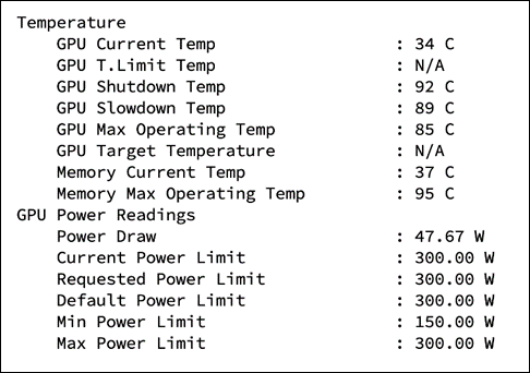
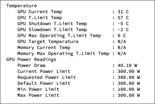
While stress tests are running, maximum core and memory utilization was observed on both GPUs. The power drawn was below 160W for L40 and close to 300W for A100. Temperature of the L40 GPUs were 50-51 degree centigrade. The temperature of the A100 GPUs were 77-79 degree centigrade.
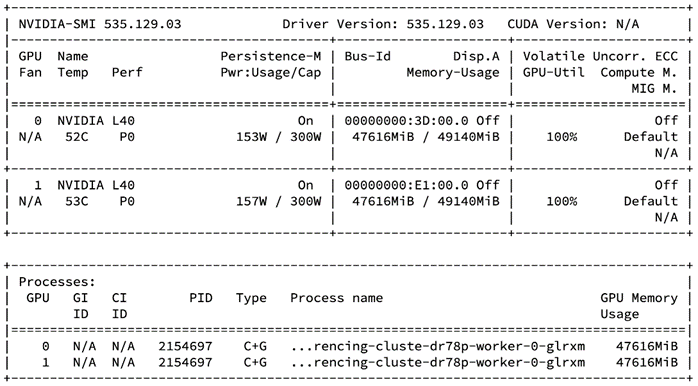
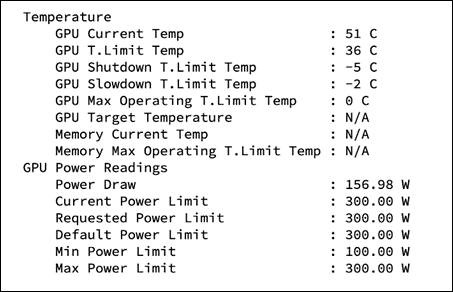
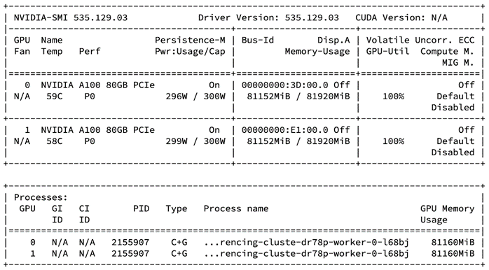
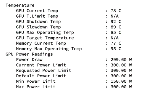
Stress tests ran successfully without any issues. No ECC errors were observed.
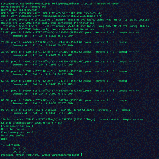
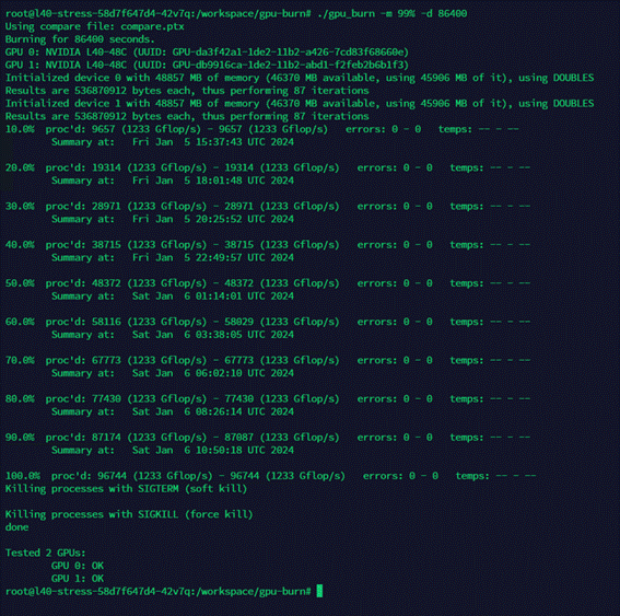
Model Performance and Sizing
This chapter contains the following:
● Llama 2
● Llama 2 Inferencing with Pytorch
● GPT-2B
● FLAN-T5
● BLOOM
● MPT-30B
● OPT : Open Pre-trained Transformer Language Models
This section examines various categories of models considered for inferencing and describes sizing guidelines.
Stable Diffusion is an open source image generation model that allows to generate images using a simple text prompt.
Stable Diffusion is a latent diffusion model created by the researchers and engineers from CompVis, Stability AI and LAION. It is trained on 512x512 images from a subset of the LAION-5B database. LAION-5B is the largest, freely accessible multi-modal dataset that currently exists.
Some of the image related tasks it performs are:
● Text-to-Image: Create an image from a text prompt.
● Image-to-Image: Create an image from an existing image and a text prompt.
● Depth-Guided Diffusion: Modify an existing image with its depth map and a text prompt.
● Instruct Pix2Pix: Modify an existing image with a text prompt.
● Stable UnCLIP Variations: Create different versions of an image with a text prompt.
● Image Upscaling: Create a high-resolution image from an existing image with a text prompt.
● Diffusion Inpainting: Modify specific areas of an existing image with an image mask and a text prompt.
Table 13 lists the different versions of Stable Diffusion.
Table 13. Stable Diffusion versions
| Model Name |
Models in Hugging Face |
| Stable Diffusion 1.4 |
|
| Stable Diffusion 1.5 |
|
| Stable Diffusion 2.0 |
|
| Stable Diffusion 2.1 |
|
| Stable Diffusion XL |
https://huggingface.co/stabilityai/stable-diffusion-xl-base-1.0 |
A sample Dockerfile to build the image is provided below for reference. It is based on the ‘stable-diffusion-docker’ Git repository from https://github.com/fboulnois/stable-diffusion-docker.
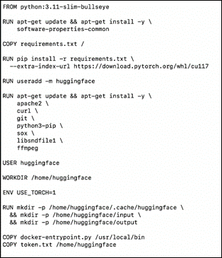
A sample deployment for Stable Diffusion is provided below:
Jupyter server is started, and all the tests were performed in the Jupyter notebook. The ‘docker-entrypoint.py’ command is run with different options.
The following image is generated by Stable Diffusion 2.0 for the prompt “Photo of an astronaut riding a horse on mars.”

The following image is generated by Stable Diffusion XL 1.0-base model for the prompt “A majestic lion jumping from a big stone at night.”

Openjourney is an open source Stable Diffusion fine tuned model on Midjourney images.
Note: We used the same inferencing method as Stable Diffusion for Openjourney.
The following image is generated for the prompt “Retro series of different cars with different colors and shapes, mdjrny-v4 style.”

The pod was created requesting one GPU. The inferencing was run with one A100 GPU. 98% of tensor core utilization with 8.3 Gigabyte of memory was consumed.
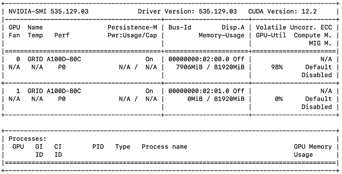
Dreamlike Diffusion 1.0 is SD 1.5 fine tuned on high quality art, made by dreamlike.art. We used the same inferencing method as Stable Diffusion for Openjourney as well.
The following image is generated by the prompt “dreamlikeart, a grungy woman with rainbow hair, travelling between dimensions, dynamic pose, happy, soft eyes and narrow chin, extreme bokeh, dainty figure, long hair straight down, Torn Kawaii shirt and baggy jeans, In the style of Jordan Grimmer and Greg Rutkowski, crisp lines and color, complex background, particles, lines, wind, concept art, sharp focus, vivid colors.”

The pod was created requesting one GPU. The inferencing was run with one A100 GPU. 98% of tensor core utilization with 6.1 Gigabyte of memory was consumed.
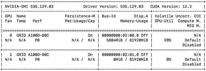
Hotshot-XL is an AI text-to-GIF model trained to work alongside Stable Diffusion XL. Hotshot-XL was trained to generate 1 second GIFs at 8 FPS.
Hotshot-XL can generate GIFs with any fine-tuned SDXL model. It is possible to make GIFs with any existing or newly fine-tuned SDXL model.
More information for the model is available in the Git repo: https://github.com/hotshotco/Hotshot-XL
Hugging face: https://huggingface.co/hotshotco/Hotshot-XL
A GIF image is generated for the prompt “whale jumping out of the ocean.”
The pod was created requesting one GPU. The inferencing was run with one L40 GPU. 98% of tensor core utilization with 11 Gigabyte of memory was consumed.
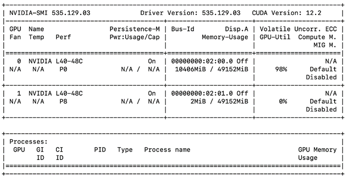
Llama-2 is an open source large language model available for public research and commercial use, It is an auto-regressive language model that uses an optimized transformer architecture. The tuned versions use supervised fine-tuning (SFT) and reinforcement learning with human feedback (RLHF) to align to human preferences for helpfulness and safety.
Llama 2 is a collection of pretrained and fine-tuned generative text models ranging in scale from 7 billion to 70 billion parameters. We considered a model size of 7B and 13B parameters for validation. Llama 2 was trained between January 2023 and July 2023.
| Model Details |
Scenario |
vGPUs |
Infrastructure |
| Llama 2-7B-Chat Llama 2-13B-Chat (Llama models converted to NeMo)
Size: 7B and 13B Parameters Precision: BF16
Inferencing Server: Triton Inference Server
|
Number of runs: 10
Batch Size: 1,2,4 and 8 |
2 X L40-48C & 2 X A100D-80C |
Red Hat OpenShift 4.14 deployed on VMware vSphere
Resources of worker node with GPUs: CPUs: 128 Cores Per Socket: 64 Memory: 128GB Disk Size: 700GB |
Model Download
Llama models are converted to NeMo format to run the inferencing on Triton Inference Server. Model can be downloaded from NGC.
Tests were run with different batch sizes. Tests focused on performance comparison between L40-48C and A100D-80C virtual GPUs running model with one and two vGPUs. Hence separate tests were run for 2 X L40-48C and 2 X A100D-80C Virtual GPUs with one and two GPUs. Latency and Throughput were measured.
Figure 113 is from the DCGM Exporter Dashboard. It shows the A100 GPU utilization as the benchmark tests progresses with LLAMA 2 7B and 13B with 2 GPUs. The GPU Framebuffer Memory utilization increases with the increase of input dataset and output length.
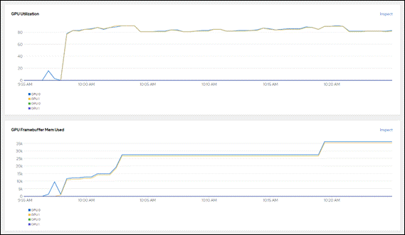
Metrics shown by nvidia-smi also matches with the data shown by NVIDIA DCGM Exporter dashboard (Figure 114).
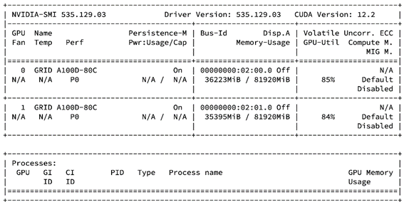
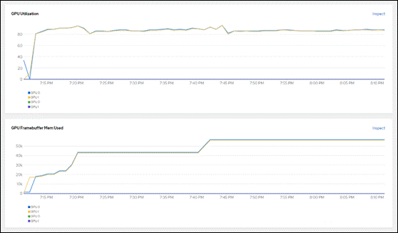
Table 15 lists the details of inference performance for three different configurations.
● Input Tokens Length: 128 and Output Tokens Length: 20
● Input Tokens Length: 256 and Output Tokens Length: 100
● Input Tokens Length: 512 and Output Tokens Length: 300
Table 15. Inference Performance for Llama 2 for Input Tokens Length: 128 and Output Tokens Length: 20
| Input Tokens Length: 128 and Output Tokens Length: 20 |
||||||||
| Model |
Batch Size |
Average Latency (ms) |
Average Throughput (sentences) |
GPUs |
||||
| A100 |
L40 |
A100 |
L40 |
|||||
| Llama 2-7B-Chat |
1 |
241.1 |
379.9 |
4.1 |
2.632 |
1 |
||
| 2 |
249.9 |
394.5 |
8.0 |
5.1 |
1 |
|||
| 4 |
280.2 |
429.5 |
14.3 |
9.4 |
1 |
|||
| 8 |
336.4 |
505.5 |
23.8 |
15.9 |
1 |
|||
| 1 |
197.1 |
252.5 |
5.1 |
4.0 |
2 |
|||
| 2 |
204.1 |
270.7 |
9.8 |
7.4 |
2 |
|||
| 4 |
230.2 |
310.5 |
17.4 |
12.9 |
2 |
|||
| 8 |
312.6 |
403.3 |
25.5 |
19.9 |
2 |
|||
| Llama 2-13B-Chat |
1 |
282.6 |
461.4 |
3.6 |
2.2 |
1 |
||
| 2 |
303.8 |
487.5 |
6.6 |
4.1 |
1 |
|||
| 4 |
347.4 |
552.1 |
11.5 |
7.3 |
1 |
|||
| 8 |
433.7 |
693.9 |
18.5 |
11.6 |
1 |
|||
| 1 |
211.6 |
292.7 |
4.7 |
3.4 |
2 |
|||
| 2 |
225.5 |
317.6 |
8.9 |
6.3 |
2 |
|||
| 4 |
282.4 |
394.4 |
14.2 |
10.2 |
2 |
|||
| 8 |
366.4 |
510.9 |
21.9 |
15.6 |
2 |
|||
Table 16. Inference Performance for Llama 2 for Input Tokens Length: 256 and Output Tokens Length: 100
| Input Tokens Length: 256 and Output Tokens Length: 100 |
||||||||
| Model |
Batch Size |
Average Latency (ms) |
Average Throughput (sentences) |
GPUs |
||||
| A100 |
L40 |
A100 |
L40 |
|||||
| Llama 2-7B-Chat |
1 |
1207.3 |
1867.3 |
0.9 |
0.6 |
1 |
||
| 2 |
1229.2 |
1946.0 |
1.6 |
1.0 |
1 |
|||
| 4 |
1337.9 |
2062.1 |
3.0 |
1.9 |
1 |
|||
| 8 |
1506.2 |
2307.3 |
5.3 |
3.5 |
1 |
|||
| 1 |
889.6 |
1167.7 |
1.1 |
0.9 |
2 |
|||
| 2 |
933.2 |
1248.4 |
2.2 |
1.6 |
2 |
|||
| 4 |
1012.2 |
1365.1 |
4.0 |
2.9 |
2 |
|||
| 8 |
1292.8 |
1650.0 |
6.2 |
4.9 |
2 |
|||
| Llama 2-13B-Chat |
1 |
2133.6 |
3439.5 |
0.5 |
0.3 |
1 |
||
| 2 |
2218.8 |
3600.0 |
1.0 |
0.6 |
1 |
|||
| 4 |
2376.7 |
3802.4 |
1.7 |
1.1 |
1 |
|||
| 8 |
2657.6 |
4193.7 |
3.0 |
2.0 |
1 |
|||
| 1 |
1411.9 |
2024.1 |
0.8 |
0.5 |
2 |
|||
| 2 |
1502.3 |
2131.3 |
1.3 |
1.0 |
2 |
|||
| 4 |
1754.9 |
2416.9 |
2.3 |
1.7 |
2 |
|||
| 8 |
2001.5 |
2777.6 |
4.0 |
2.9 |
2 |
|||
Table 17. Inference Performance for Llama 2 for Input Tokens Length: 512 and Output Tokens Length: 300
| Input Tokens Length: 512 and Output Tokens Length: 300 |
||||||||
| Model |
Batch Size |
Average Latency (ms) |
Average Throughput (sentences) |
GPUs |
||||
| A100 |
L40 |
A100 |
L40 |
|||||
| Llama 2-7B-Chat |
1 |
3625.2 |
5615.9 |
0.3 |
0.2 |
1 |
||
| 2 |
3708.2 |
5888.3 |
0.6 |
0.4 |
1 |
|||
| 4 |
4077.6 |
6280.7 |
1.0 |
0.7 |
1 |
|||
| 8 |
4567.5 |
7180.2 |
1.8 |
1.1 |
1 |
|||
| 1 |
2681.4 |
3495.2 |
0.4 |
0.3 |
2 |
|||
| 2 |
2781.9 |
3697.0 |
0.7 |
0.6 |
2 |
|||
| 4 |
3005.4 |
4036.5 |
1.3 |
1.0 |
2 |
|||
| 8 |
3831.8 |
4960.3 |
2.1 |
1.6 |
2 |
|||
| Llama 2-13B-Chat |
1 |
6399.9 |
10326.9 |
0.2 |
0.1 |
1 |
||
| 2 |
6656.7 |
10856.4 |
0.3 |
0.2 |
1 |
|||
| 4 |
7183.0 |
11558.0 |
0.6 |
0.4 |
1 |
|||
| 8 |
8010.6 |
12919.2 |
1.0 |
0.6 |
1 |
|||
| 1 |
4249.4 |
6040.6 |
0.3 |
0.2 |
2 |
|||
| 2 |
4474.8 |
6340.2 |
0.5 |
0.3 |
2 |
|||
| 4 |
5181.0 |
7226.7 |
0.8 |
0.6 |
2 |
|||
| 8 |
5870.3 |
8264.1 |
1.4 |
1.0 |
2 |
|||
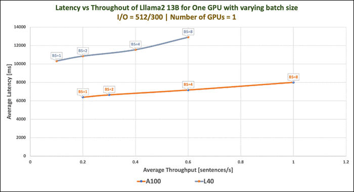
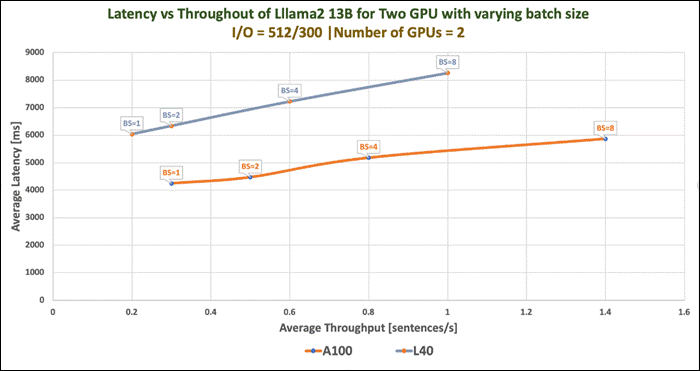
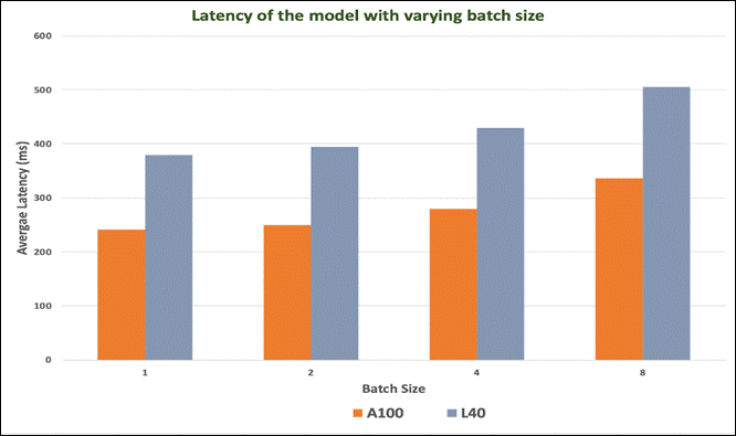
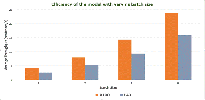
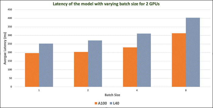
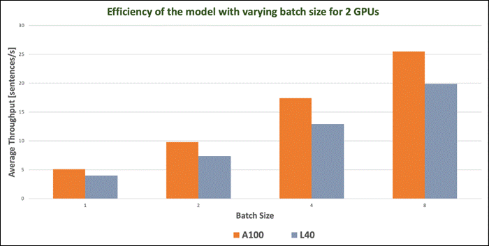
Llama 2 Inferencing with Pytorch
This section describes NVIDIA Triton Inference Server and inferencing with PyTorch.
PyTorch is an optimized tensor library for deep learning using GPUs and CPUs. Automatic differentiation is done with a tape-based system at both a functional and neural network layer level. This functionality brings a high level of flexibility and speed as a deep learning framework and provides accelerated NumPy-like functionality. NGC Containers are the easiest way to get started with PyTorch. The PyTorch NGC Container comes with all dependencies included, providing an easy place to start developing common applications, such as conversational AI, natural language processing (NLP), recommenders, and computer vision.
The PyTorch NGC Container is optimized for GPU acceleration and contains a validated set of libraries that enable and optimize GPU performance. This container also contains software for accelerating ETL (DALI, RAPIDS), Training (cuDNN, NCCL), and Inference (TensorRT) workloads.
Model Download
To download the model weights and tokenizer, it is required to accept our Meta license agreement. It can be requested from: https://ai.meta.com/resources/models-and-libraries/llama-downloads/
Sample Dockerfile to build image is provided below. The image is built with few additional Python packages.
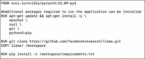
A deployment is created in OpenShift using sample YAML manifest as shown below.
A persistent storage is configured for the model repository. In this example, it is a PVC mapped to Portworx cluster. It can also be a NFS from FlashBlade. Llama-2-7b-chat and Llama-2-13b-chat are copied to the persistent storage.
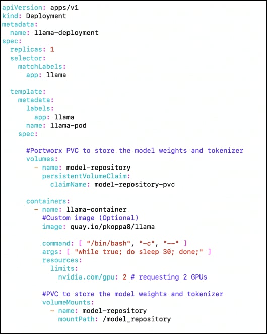
PVC definition is provided below:
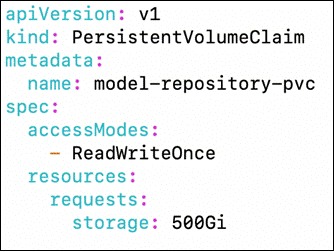
Sample run
After the deployment is running fine, you can enter the BASH of the llama-pod and run the inferencing.
The sample script(example_chat_completion.py) is modified for the prompt “what is the recipe of mayonnaise?”
Command: torchrun --nproc_per_node 2 test.py --ckpt_dir /model_repository/llama-2-13b-chat/ --tokenizer_path tokenizer.model --max_seq_len 1024 --max_batch_size 6
The following is the response from llama-2-13b-chat model running on worker node with L40 GPU.

Figure 126 shows the maximum utilization of GPU resources when the model was running. Model was started with 2 GPUs and hence utilization observed on both GPUs.
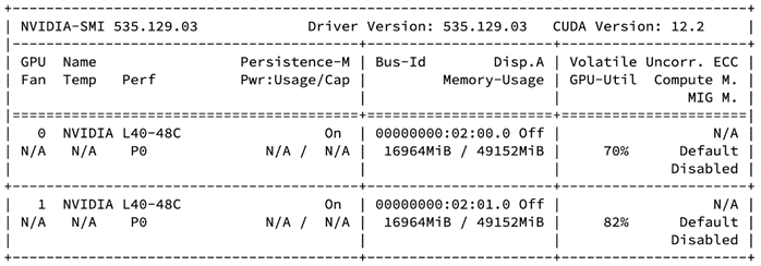
Nemotron-3 family of models is GPT-based decoder-only generative text models compatible with NVIDIA NeMo Framework. Models are optimized for building production-ready generative AI applications for the enterprise.
The fine-tuned versions of Nemotron-3 are available with Reinforcement Learning from Human Feedback (RLHF), Supervised Fine-tuning (SFT) and SteerLM.
Several variants of the model are available:
● NV-GPT-8B-Base-4k
NV-GPT-8B-Base-4K is a large language foundation model for enterprises to build custom LLMs. This foundation model has 8 billion parameters and supports a context length of 4,096 tokens.
● NV-GPT-8B-Base-16k
NV-GPT-8B-Base-16K is a large language foundation model for enterprises to build their own LLMs. NV-GPT-8B-Base-16k is a pretrained model with 8 billion parameters and a context length of 16,384 tokens.
● NV-GPT-8B-QA-4k
NV-GPT-8B-QA-4k is a 8 billion parameter generative language model based on the NV-GPT-8B base model. The model has been further fine-tuned specifically for Question and Answer method.
● NV-GPT-8B-Chat-4k-RLHF
NV-GPT-8B-Chat-4k-RLHF is a large language model based on the 8B foundation model. It takes input with context length up to 4k. The model has been further fine-tuned for instruction following using Reinforcement Learning from Human Feedback (RLHF).
● NV-GPT-8B-Chat-4k-SteerLM
NV-GPT-8B-Chat-4k-SteerLM is an 8 billion parameter generative language model based on the NVIDIA 8B GPT base model. It has been customized using the SteerLM method developed by NVIDIA.
● NV-GPT-8B-Chat-4k-SFT
NV-GPT-8B-Chat-4k-SFT is a large language model based on the 8B foundation model. It takes input with context length up to 4k. The model has been further fine-tuned for instruction following using Supervised Fine-tuning (SFT).
| Model Details |
Scenario |
vGPUs |
Infrastructure |
| NV-GPT-8B-Chat-4k-SFT
Model Size: 8B Parameters
Tensor type: BF16
Inferencing Server: Triton Inference Server
|
Number of runs: 100
Batch Sie: 1,2,4 and 8
|
2 X A100D-80C |
Red Hat OpenShift 4.14 deployed on VMware vSphere
Resources of worker node with GPUs: CPUs: 128 Cores Per Socket: 64 Memory: 128GB Disk Size: 700GB |
Model Download
Model can be downloaded from Hugging Face, here: https://huggingface.co/nvidia/nemotron-3-8b-chat-4k-sft
Test Results
Benchmark was run with different batch sizes(1,2,4 and 8). Tests focused on performance comparison of NV-GPT-8B-Chat-4k-SFT model with 1 X A100 Virtual GPU and 2 X A100 Virtual GPU. Separate tests were run with one A100 and two. Latency and Throughput were measured.
Table 19. Inference Performance for NV-GPT-8B-Chat-4k-SFT
| Batch Size |
Average Latency (ms) |
Average Throughput (sentence/s) |
|||
| One GPU |
Two GPU |
One GPU |
Two GPU |
||
| Input Tokens Length: 128 and Output Tokens Length: 20 |
|||||
| 1 |
256.1 |
192.4 |
3.9 |
5.2 |
|
| 2 |
265.4 |
203.3 |
7.6 |
9.9 |
|
| 4 |
292.6 |
232.4 |
13.7 |
17.2 |
|
| 8 |
343.8 |
308.7 |
23.3 |
26.0 |
|
| Input Tokens Length: 256 and Output Tokens Length: 20 |
|||||
| 1 |
268.1 |
202.2 |
3.7 |
5.0 |
|
| 2 |
289.0 |
226.1 |
7.0 |
8.9 |
|
| 4 |
340.3 |
276.6 |
11.8 |
14.5 |
|
| 8 |
434.9 |
392.6 |
18.4 |
20.4 |
|
| Input Tokens Length: 512 and Output Tokens Length: 20 |
|||||
| 1 |
293.8 |
226.4 |
3.4 |
4.4 |
|
| 2 |
338.1 |
271.7 |
6.0 |
7.4 |
|
| 4 |
430.0 |
359.9 |
9.3 |
11.1 |
|
| 8 |
598.8 |
569.4 |
13.4 |
14.1 |
|
| Input Tokens Length: 2048 and Output Tokens Length: 20 |
|||||
| 1 |
433.0 |
368.7 |
2.3 |
2.7 |
|
| 2 |
588.0 |
538.9 |
3.4 |
3.7 |
|
| 4 |
943.6 |
880.2 |
4.3 |
4.6 |
|
| 8 |
1616.9 |
1584.3 |
5.0 |
5.1 |
|
| Input Tokens Length: 128 and Output Tokens Length: 100 |
|||||
| 1 |
1251.4 |
877.7 |
0.8 |
1.1 |
|
| 2 |
1266.4 |
900.9 |
1.6 |
2.2 |
|
| 4 |
1334.3 |
962.3 |
3.0 |
4.2 |
|
| 8 |
1444.8 |
1182.3 |
5.6 |
6.8 |
|
| Input Tokens Length: 256 and Output Tokens Length: 100 |
|||||
| 1 |
1276.8 |
897.6 |
0.8 |
1.1 |
|
| 2 |
1302.4 |
934.2 |
1.6 |
2.1 |
|
| 4 |
1404.6 |
1019.3 |
2.9 |
4.0 |
|
| 8 |
1565.2 |
1290.7 |
5.1 |
6.2 |
|
| Input Tokens Length: 512 and Output Tokens Length: 100 |
|||||
| 1 |
1307.5 |
936.8 |
0.8 |
1.1 |
|
| 2 |
1358.6 |
995.5 |
1.5 |
2.0 |
|
| 4 |
1523.4 |
1122.5 |
2.6 |
3.6 |
|
| 8 |
1790.3 |
1494.9 |
4.5 |
5.4 |
|
| Input Tokens Length: 2048 and Output Tokens Length: 100 |
|||||
| 1 |
1534.3 |
1154.7 |
0.7 |
0.9 |
|
| 2 |
1713.0 |
1335.1 |
1.2 |
1.5 |
|
| 4 |
2239.7 |
1713.9 |
1.8 |
2.3 |
|
| 8 |
3123.9 |
2711.5 |
2.6 |
3.0 |
|
| Input Tokens Length: 128 and Output Tokens Length: 200 |
|||||
| 1 |
2499.3 |
1742.9 |
0.4 |
0.6 |
|
| 2 |
2524.3 |
1781.9 |
0.8 |
1.1 |
|
| 4 |
2649.2 |
1884.9 |
1.5 |
2.1 |
|
| 8 |
2838.9 |
2294.2 |
2.8 |
3.5 |
|
| Input Tokens Length: 256 and Output Tokens Length: 200 |
|||||
| 1 |
2527.4 |
1771.5 |
0.4 |
0.6 |
|
| 2 |
2566.1 |
1824.4 |
0.8 |
1.1 |
|
| 4 |
2743.4 |
1954.1 |
1.5 |
2.1 |
|
| 8 |
3003.4 |
2424.6 |
2.7 |
3.3 |
|
| Input Tokens Length: 512 and Output Tokens Length: 200 |
|||||
| 1 |
2580.1 |
1827.0 |
0.4 |
0.6 |
|
| 2 |
2639.5 |
1902.6 |
0.8 |
1.1 |
|
| 4 |
2909.5 |
2077.8 |
1.4 |
2.0 |
|
| 8 |
3298.2 |
2669.0 |
2.4 |
3.0 |
|
| Input Tokens Length: 2048 and Output Tokens Length: 200 |
|||||
| 1 |
2907.6 |
2138.5 |
0.4 |
0.5 |
|
| 2 |
3102.7 |
2341.0 |
0.7 |
0.9 |
|
| 4 |
3870.6 |
2791.3 |
1.0 |
1.5 |
|
| 8 |
5066.9 |
4121.9 |
1.6 |
2.0 |
|
| Input Tokens Length: 128 and Output Tokens Length: 300 |
|||||
| 1 |
3748.7 |
2614.0 |
0.3 |
0.4 |
|
| 2 |
3785.8 |
2671.0 |
0.5 |
0.8 |
|
| 4 |
3992.6 |
2817.9 |
1.0 |
1.4 |
|
| 8 |
4267.9 |
3422.1 |
1.9 |
2.4 |
|
| Input Tokens Length: 256 and Output Tokens Length: 300 |
|||||
| 1 |
3792.2 |
2649.3 |
0.3 |
0.4 |
|
| 2 |
3844.0 |
2718.5 |
0.5 |
0.8 |
|
| 4 |
4107.3 |
2894.6 |
1.0 |
1.4 |
|
| 8 |
4454.5 |
3574.5 |
1.8 |
2.2 |
|
| Input Tokens Length: 512 and Output Tokens Length: 300 |
|||||
| 1 |
3865.9 |
2722.1 |
0.3 |
0.4 |
|
| 2 |
3946.1 |
2816.9 |
0.6 |
0.7 |
|
| 4 |
4308.3 |
3035.8 |
1.0 |
1.3 |
|
| 8 |
4813.1 |
3861.5 |
1.7 |
2.1 |
|
| Input Tokens Length: 2048 and Output Tokens Length: 300 |
|||||
| 1 |
4293.8 |
3128.6 |
0.2 |
0.3 |
|
| 2 |
4506.4 |
3348.7 |
0.5 |
0.6 |
|
| 4 |
5526.6 |
3855.9 |
0.7 |
1.1 |
|
| 8 |
7005.8 |
5554.6 |
1.2 |
1.5 |
|
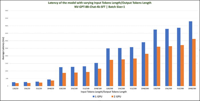
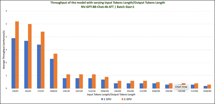
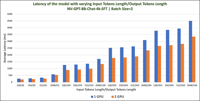
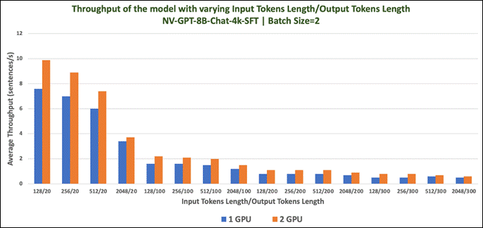
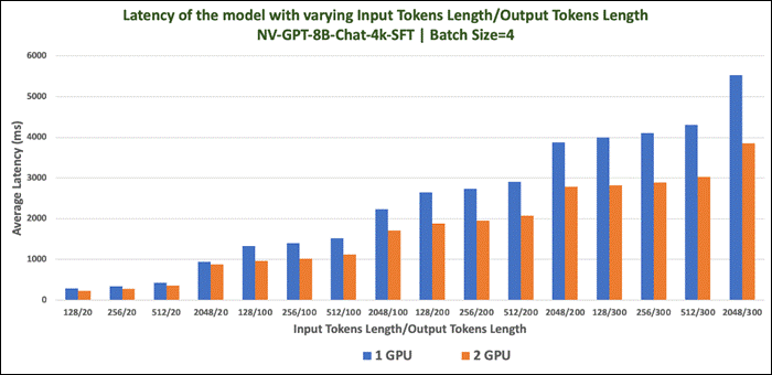
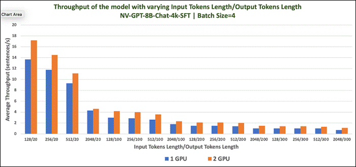
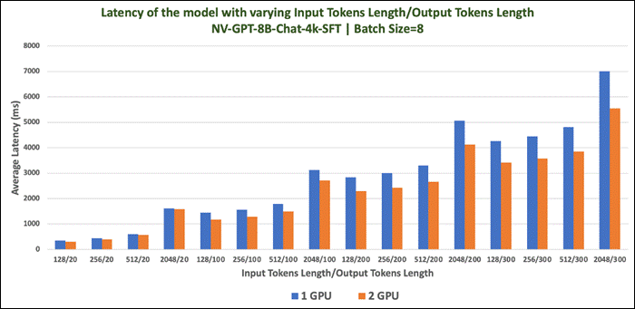
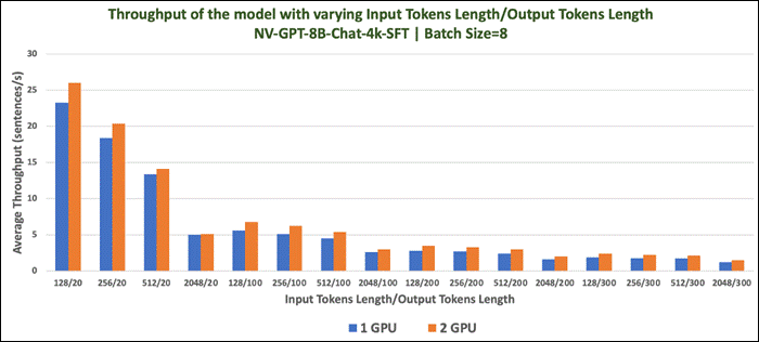
GPT-2B is a transformer-based language model. GPT refers to a class of transformer decoder-only models similar to GPT-2 and 3 while 2B refers to the total trainable parameter count (2 Billion)
This model was trained on 1.1T tokens with NeMo.
| Model Details |
Scenario |
vGPUs |
Infrastructure |
| nvidia/GPT-2B-001
Model Size: 2B parameters
Tensor type: BF16
Inferencing Server: Triton Inference Server
|
Number of runs: 100
Batch Sie: 1,2,4 and 8
|
2 X A100D-80C |
Red Hat OpenShift 4.14 deployed on VMware vSphere
Resources of worker node with GPUs: CPUs: 128 Cores Per Socket: 64 Memory: 128GB Disk Size: 700GB |
Model Download
Model can be downloaded from Hugging Face, here: https://huggingface.co/nvidia/GPT-2B-001
Tests Results
Benchmark was run with different batch sizes(1,2,4 and 8). Tests focused on performance comparison of GPT-2B model with 1 X A100 Virtual GPU and 2 X A100 Virtual GPU. Separate tests were run with one A100 and two. Latency and Throughput were measured.
Table 21. Inference Performance for GPT-2B-001
| Batch Size |
Average Latency (ms) |
Average Throughput (sentence/s) |
|||
| One GPU |
Two GPU |
One GPU |
Two GPU |
||
| Input Tokens Length: 128 and Output Tokens Length: 20 |
|||||
| 1 |
99.5 |
100.8 |
10.1 |
10.0 |
|
| 2 |
101.7 |
108.2 |
19.7 |
18.5 |
|
| 4 |
108.2 |
118.6 |
37.0 |
33.7 |
|
| 8 |
126.0 |
149.2 |
63.5 |
53.6 |
|
| Input Tokens Length: 256 and Output Tokens Length: 20 |
|||||
| 1 |
103.9 |
105.4 |
9.6 |
9.5 |
|
| 2 |
109.7 |
116.0 |
18.2 |
17.2 |
|
| 4 |
121.3 |
134.1 |
33.0 |
29.8 |
|
| 8 |
155.0 |
183.2 |
51.6 |
43.7 |
|
| Input Tokens Length: 512 and Output Tokens Length: 20 |
|||||
| 1 |
109.8 |
114.7 |
9.1 |
8.7 |
|
| 2 |
121.9 |
132.3 |
16.4 |
15.1 |
|
| 4 |
148.5 |
167.6 |
27.0 |
23.9 |
|
| 8 |
202.5 |
243.2 |
39.5 |
32.9 |
|
| Input Tokens Length: 2048 and Output Tokens Length: 20 |
|||||
| 1 |
161.1 |
174.3 |
6.2 |
5.8 |
|
| 2 |
205.2 |
236.6 |
9.8 |
8.5 |
|
| 4 |
294.7 |
362.2 |
13.6 |
11.1 |
|
| 8 |
501.7 |
612.9 |
16.0 |
13.1 |
|
| Input Tokens Length: 128 and Output Tokens Length: 100 |
|||||
| 1 |
460.9 |
443.1 |
2.2 |
2.3 |
|
| 2 |
466.1 |
464.3 |
4.3 |
4.3 |
|
| 4 |
479.3 |
489.7 |
8.4 |
8.2 |
|
| 8 |
531.3 |
586.8 |
15.1 |
13.6 |
|
| Input Tokens Length: 256 and Output Tokens Length: 100 |
|||||
| 1 |
474.0 |
455.6 |
2.1 |
2.2 |
|
| 2 |
481.4 |
480.9 |
4.2 |
4.2 |
|
| 4 |
501.3 |
514.1 |
8.0 |
7.8 |
|
| 8 |
578.4 |
630.8 |
13.9 |
12.7 |
|
| Input Tokens Length: 512 and Output Tokens Length: 100 |
|||||
| 1 |
490.9 |
475.2 |
2.1 |
2.1 |
|
| 2 |
505.9 |
506.6 |
4.0 |
4.0 |
|
| 4 |
545.1 |
558.9 |
7.3 |
7.2 |
|
| 8 |
654.7 |
706.3 |
12.2 |
11.3 |
|
| Input Tokens Length: 2048 and Output Tokens Length: 100 |
|||||
| 1 |
598.9 |
590.7 |
1.7 |
1.7 |
|
| 2 |
648.3 |
670.7 |
3.1 |
3.0 |
|
| 4 |
757.5 |
805.8 |
5.3 |
5.0 |
|
| 8 |
1103.8 |
1144.8 |
7.3 |
7.0 |
|
| Input Tokens Length: 128 and Output Tokens Length: 200 |
|||||
| 1 |
920.9 |
876.8 |
1.1 |
1.1 |
|
| 2 |
926.8 |
916.7 |
2.1 |
2.2 |
|
| 4 |
949.4 |
960.8 |
4.2 |
4.2 |
|
| 8 |
1050.9 |
1142.5 |
7.6 |
7.0 |
|
| Input Tokens Length: 256 and Output Tokens Length: 200 |
|||||
| 1 |
940.8 |
896.3 |
1.1 |
1.1 |
|
| 2 |
948.6 |
940.2 |
2.1 |
2.1 |
|
| 4 |
980.5 |
991.8 |
4.1 |
4.0 |
|
| 8 |
1113.5 |
1196.0 |
7.2 |
6.7 |
|
| Input Tokens Length: 512 and Output Tokens Length: 200 |
|||||
| 1 |
969.9 |
929.1 |
1.0 |
1.1 |
|
| 2 |
985.3 |
980.6 |
2.0 |
2.0 |
|
| 4 |
1036.9 |
1052.4 |
3.9 |
3.8 |
|
| 8 |
1225.5 |
1286.1 |
6.6 |
6.2 |
|
| Input Tokens Length: 2048 and Output Tokens Length: 200 |
|||||
| 1 |
1151.6 |
1113.9 |
0.9 |
0.9 |
|
| 2 |
1207.0 |
1216.8 |
1.7 |
1.7 |
|
| 4 |
1348.1 |
1375.2 |
3.0 |
2.9 |
|
| 8 |
1863.2 |
1817.5 |
4.3 |
4.4 |
|
| Input Tokens Length: 128 and Output Tokens Length: 300 |
|||||
| 1 |
1385.2 |
1317.7 |
0.7 |
0.8 |
|
| 2 |
1390.9 |
1376.7 |
1.5 |
1.5 |
|
| 4 |
1428.4 |
1437.5 |
2.8 |
2.8 |
|
| 8 |
1584.3 |
1703.3 |
5.1 |
4.7 |
|
| Input Tokens Length: 256 and Output Tokens Length: 300 |
|||||
| 1 |
1410.1 |
1339.1 |
0.7 |
0.8 |
|
| 2 |
1420.9 |
1401.7 |
1.4 |
1.4 |
|
| 4 |
1464.6 |
1473.3 |
2.7 |
2.7 |
|
| 8 |
1662.3 |
1766.0 |
4.8 |
4.5 |
|
| Input Tokens Length: 512 and Output Tokens Length: 300 |
|||||
| 1 |
1453.1 |
1386.6 |
0.7 |
0.7 |
|
| 2 |
1469.4 |
1457.5 |
1.4 |
1.4 |
|
| 4 |
1537.7 |
1546.7 |
2.6 |
2.6 |
|
| 8 |
1805.4 |
1870.2 |
4.4 |
4.3 |
|
| Input Tokens Length: 2048 and Output Tokens Length: 300 |
|||||
| 1 |
1701.2 |
1643.8 |
0.6 |
0.6 |
|
| 2 |
1759.4 |
1764.1 |
1.1 |
1.1 |
|
| 4 |
1923.9 |
1944.2 |
2.1 |
2.1 |
|
| 8 |
2627.9 |
2499.4 |
3.1 |
3.2 |
|
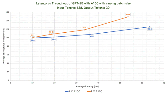
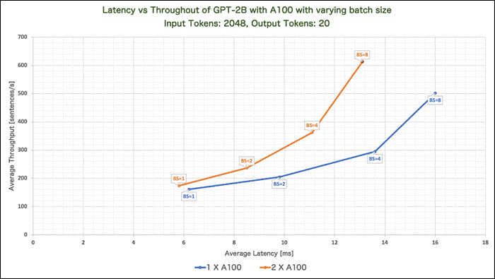
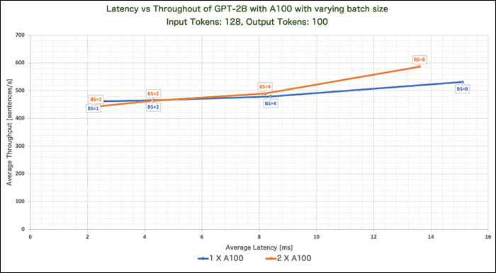
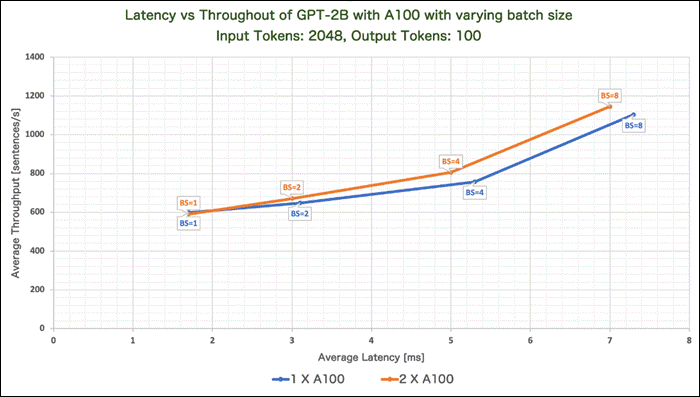
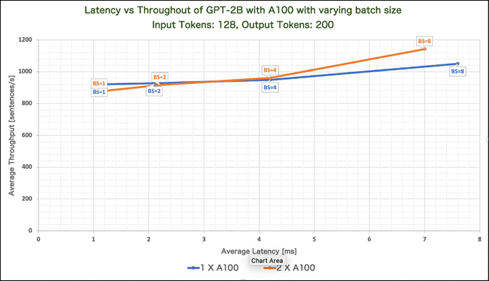
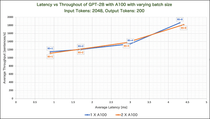
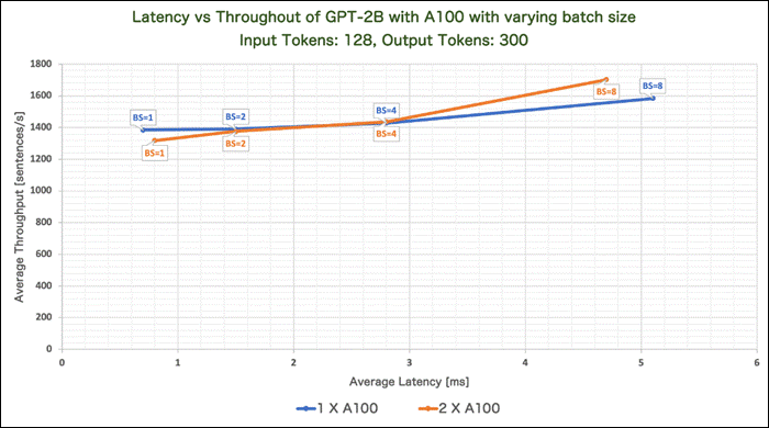
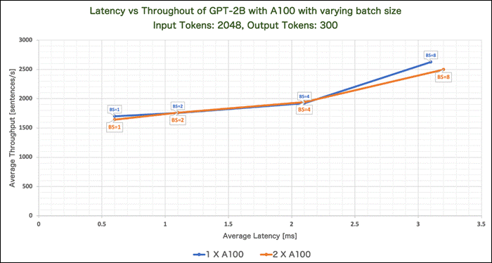
FLAN-T5 is a combination of a network and a model. FLAN is an abbreviation for Finetuned Language Net. T5 is a large language model developed and published by Google. This model is an improvement on the T5 model by improving the effectiveness of the zero-shot learning.
Several versions of FLAN-T5 are available by Google:
● Flan-T5 small
● Flan-T5-base
● Flan-T5-large
● Flan-T5-XL
● Flan-T5 XXL
Note: We considered the Flan-T5-XL and Flan-T5 XXL versions for validation.
Table 22. Validation Scenario
| Model Details |
Scenario |
vGPUs |
Infrastructure |
| google/flan-t5-xl google/flan-t5-xl Model Size: Flan-T5-XL – 2.85B parameters Flan-T5 XXL – 11.3 B parameters
Tensor type: F32
Inferencing Server: Text Generation Inference
|
Number of runs: 100
Batch Sie: 1,2,4,8,10,25,50 and 100
|
2 X A100D-80C |
Red Hat OpenShift 4.14 deployed on VMware vSphere
Resources of worker node with GPUs: CPUs: 128 Cores Per Socket: 64 Memory: 128GB Disk Size: 700GB |
Model Download
Model can be downloaded from Hugging Face, here: Flan-T5-XL: https://huggingface.co/google/flan-t5-xl or here: Flan-T5-XXL: https://huggingface.co/google/flan-t5-xxl
Sample Run
Figure 127 is an example of running inference of the Flan-T5 XXL with 2 shards running on 2XA100 GPUs.
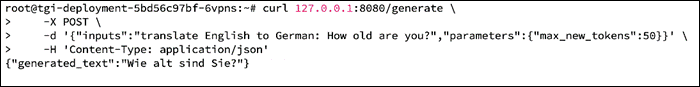
Tests Results
Benchmark was run with different batch sizes (1,2,4,8,10,25,50 and 100). Tests focused on performance comparison between the Flan-T5-XL and Flan-T5 XXL with and without sharding enabled. Hence separate tests were run for Flan-T5-XL and Flan-T5 XXL on A100 Virtual GPUs. Prefill Latency, Prefill Throughput, Decode Total Latency, Decode Token Latency, Decode Throughput were measured.
Table 23. Inference Performance of FLAN-T5 with shard disabled
| Model |
Batch Size |
Prefill Latency |
Decode Token Latency |
Decode Total Latency |
Prefill Throughput |
Decode Throughput |
| FLAN-T5 XL |
1 |
24.9 |
14.7 |
103.0 |
40.1 |
67.9 |
| 2 |
26.1 |
16.2 |
113.3 |
76.64 |
123.7 |
|
| 4 |
27.6 |
16.7 |
116.8 |
145.2 |
239.9 |
|
| 8 |
28.8 |
17.6 |
123.2 |
277.8 |
454.5 |
|
| 10 |
29.0 |
17.9 |
125.5 |
345.1 |
558.0 |
|
| 25 |
33.1 |
20.2 |
141.5 |
756.8 |
1238.6 |
|
| 50 |
40.0 |
25.5 |
178.4 |
1251.3 |
1963.4 |
|
| 100 |
59.5 |
35.2 |
246.5 |
1681.4 |
2841.9 |
|
| FLAN-T5 XXL |
1 |
25.1 |
14.0 |
98.0 |
39.8 |
71.5 |
| 2 |
26.8 |
15.0 |
105.0 |
74.5 |
133.4 |
|
| 4 |
28.1 |
15.6 |
109.3 |
142.3 |
257.1 |
|
| 8 |
32.0 |
16.5 |
115.7 |
250.1 |
484.2 |
|
| 10 |
32.8 |
17.0 |
118.9 |
305.1 |
589.1 |
|
| 25 |
46.4 |
20.5 |
143.2 |
539.4 |
1222.0 |
|
| 50 |
70.7 |
26.5 |
185.8 |
707.2 |
1885.0 |
|
| 100 |
128.8 |
39.2 |
274.8 |
776.8 |
2547.2 |
Table 24. Inference Performance of FLAN-T5 with shard enabled (Number of shard =2)
| Model |
Batch Size |
Prefill Latency |
Decode Token Latency |
Decode Total Latency |
Prefill Throughput |
Decode Throughput |
| FLAN-T5 XL |
1 |
32.8 |
19.5 |
136.7 |
30.5 |
51.2 |
| 2 |
35.7 |
21.3 |
149.0 |
56.3 |
94.1 |
|
| 4 |
36.8 |
21.9 |
153.1 |
109.0 |
183.0 |
|
| 8 |
39.5 |
23.0 |
161.2 |
203.3 |
347.6 |
|
| 10 |
37.9 |
23.0 |
160.6 |
264.3 |
436.0 |
|
| 25 |
43.8 |
25.4 |
177.9 |
572.1 |
984.8 |
|
| 50 |
53.1 |
30.7 |
215.0 |
942.8 |
1628.3 |
|
| 100 |
84.2 |
39.3 |
274.9 |
1187.7 |
2546.8 |
|
| FLAN-T5 XXL |
1 |
30.9 |
18.3 |
128.3 |
32.4 |
54.6 |
| 2 |
32.4 |
19.7 |
137.6 |
61.8 |
101.9 |
|
| 4 |
34.1 |
20.2 |
141.7 |
117.6 |
197.8 |
|
| 8 |
36.6 |
21.3 |
148.9 |
220.0 |
376.6 |
|
| 10 |
37.1 |
21.7 |
151.5 |
270.2 |
462.5 |
|
| 25 |
54.2 |
25.2 |
176.6 |
462.7 |
1007.0 |
|
| 50 |
84.5 |
29.0 |
203.1 |
591.7 |
1724.2 |
|
| 100 |
138.8 |
41.1 |
287.8 |
720.7 |
2433.0 |
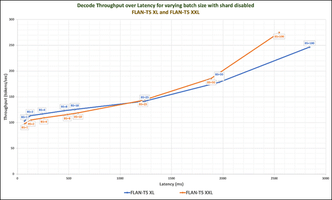
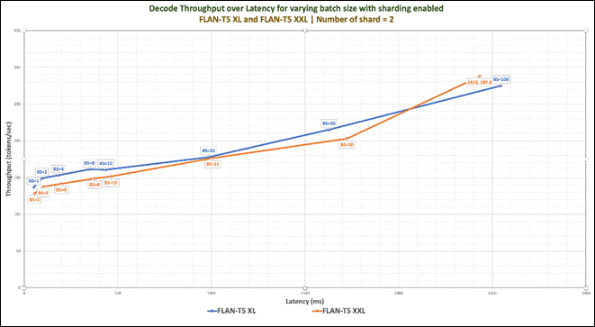
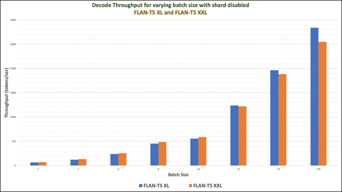
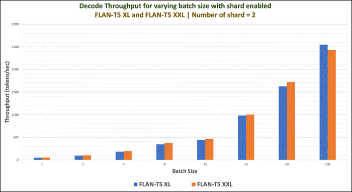
Mistral 7B is a 7-billion-parameter language model released by Mistral AI. Mistral 7B is a carefully designed language model that provides both efficiency and high performance to enable real-world applications. Due to its efficiency improvements, the model is suitable for real-time applications where quick responses are essential.
The model uses attention mechanisms like:
● grouped-query attention (GQA) for faster inference and reduced memory requirements during decoding
● sliding window attention (SWA) for handling sequences of arbitrary length with a reduced inference cost.
The model is released under the Apache 2.0 license.
| Model Details |
Scenario |
vGPUs |
Infrastructure |
| mistralai/Mistral-7B-v0.1
Size: 7.24B parameters Tensor type: BF16
Inferencing Server: Text Generation Inference
|
Number of runs: 100
Batch Sie: 1,2,4,8,10,25,50 and 100
|
2 X L40-48C
|
Red Hat OpenShift 4.14 deployed on VMware vSphere
Resources of worker node with GPUs: CPUs: 128 Cores Per Socket: 64 Memory: 128GB Disk Size: 700GB |
Model Download
Model can be downloaded from Hugging Face, here: https://huggingface.co/mistralai/Mistral-7B-v0.1
Sample Run
Figure 132 is an example of running inference of the Mistral-7B running with one X L40-48C GPUs for the input “What are the colors in a rainbow?”
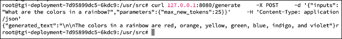
Maximum GPU utilization with the provided inferencing was running is provided in Figure 133.
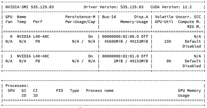
Tests Results
Benchmark was run with different batch sizes(1,2,4,8,10,25,50,100 and 200). The tests focused on performance comparison between 1 X L40-48C and 2 X L40-48C virtual GPUs. Separate tests were run for 1 X L40-48C and 2 X L40-48C Virtual GPUs. Prefill Latency, Prefill Throughput, Decode Total Latency, Decode Token Latency, Decode Throughput were measured.
Table 26. Benchmark Test Results
| GPUs |
Batch Size |
Prefill Latency |
Decode Token Latency |
Decode Total Latency |
Prefill Throughput |
Decode Throughput |
| Mistral-7B on One X L40
|
1 |
21.3 |
19.9 |
139.2 |
46.8 |
50.3 |
| 2 |
22.0 |
20.5 |
143.4 |
90.9 |
98.0 |
|
| 4 |
22.8 |
20.6 |
144.3 |
176.8 |
194.1 |
|
| 8 |
24.5 |
20.9 |
146.3 |
326.5 |
383.0 |
|
| 10 |
25.3 |
21.0 |
147.0 |
395.7 |
476.4 |
|
| 25 |
36.6 |
22.1 |
154.6 |
682.7 |
1133.2 |
|
| 50 |
74.9 |
23.5 |
164.3 |
668.1 |
2131.3 |
|
| 100 |
141.0 |
27.6 |
193.4 |
709.6 |
3622.4 |
|
| 200 |
280.8 |
43.0 |
301.3 |
713.1 |
4650.0 |
|
| Mistral-7B on Two X L40
|
1 |
43.4 |
19.6 |
137.3 |
35.7 |
54.7 |
| 2 |
47.6 |
21.3 |
149.0 |
61.2 |
100.7 |
|
| 4 |
56.0 |
21.9 |
153.1 |
94.7 |
192.8 |
|
| 8 |
78.6 |
23.4 |
163.8 |
128.0 |
352.9 |
|
| 10 |
80.1 |
23.7 |
165.6 |
145.4 |
435.0 |
|
| 25 |
103.0 |
23.3 |
163.3 |
263.7 |
1089.3 |
|
| 50 |
146.5 |
24.4 |
171.0 |
349.1 |
2062.5 |
|
| 100 |
233.7 |
29.7 |
207.6 |
433.9 |
3372.9 |
|
| 200 |
400.7 |
44.4 |
310.9 |
501.8 |
4504.9 |
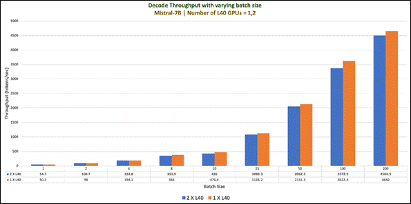
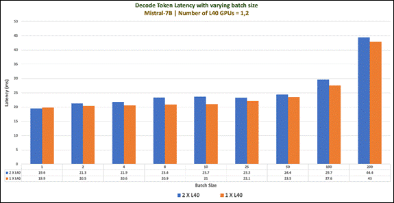
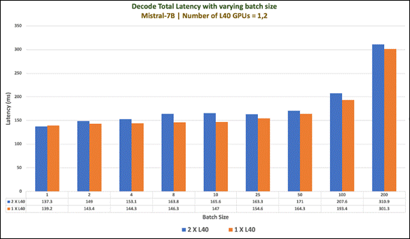
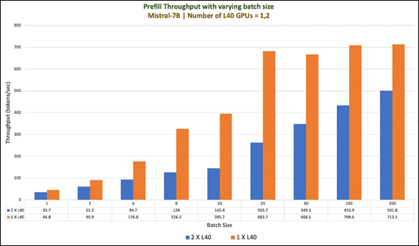
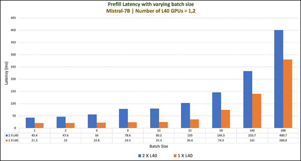
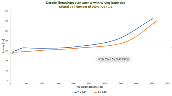
BLOOM stands for BigScience Large Open-science Open-access Multilingual Language Model.
It is a transformer-based large language model and free to the public. The architecture of BLOOM is essentially like GPT3 (auto-regressive model for next token prediction). BLOOM is trained to continue text from a prompt on vast amounts of text data using industrial-scale computational resources. As such, it can output coherent text in 46 languages and 13 programming languages that is hardly distinguishable from text written by humans. BLOOM can also be instructed to perform text tasks it hasn't been explicitly trained for, by casting them as text generation tasks.
Several smaller versions of the models have been trained on the same dataset. The model size of 7B parameters was used for validation.
| Model Details |
Scenario |
vGPUs |
Infrastructure |
| bigscience/bloom-7b1
Size: 7B Tensor type: F16
Inferencing Server: Text Generation Inference
|
Number of runs: 100
Batch Sie: 1,2,4,8,10,25,50 and 100
|
2 X L40-48C & 2 X A100D-80C |
Red Hat OpenShift 4.14 deployed on VMware vSphere
Resources of worker node with GPUs: CPUs: 128 Cores Per Socket: 64 Memory: 128GB Disk Size: 700GB |
Model Download
Model can be downloaded from Hugging Face, here: https://huggingface.co/bigscience/bloom-7b1
Tests Results
Benchmark was run with different batch sizes(1,2,4,8,10,25,50 and 100). Tests focused on performance comparison between 2 X L40-48C and 2 X A100D-80C virtual GPUs. Separate tests were run for 2 X L40-48C and 2 X A100D-80C Virtual GPUs. Prefill Latency, Prefill Throughput, Decode Total Latency, Decode Token Latency, Decode Throughput were measured.
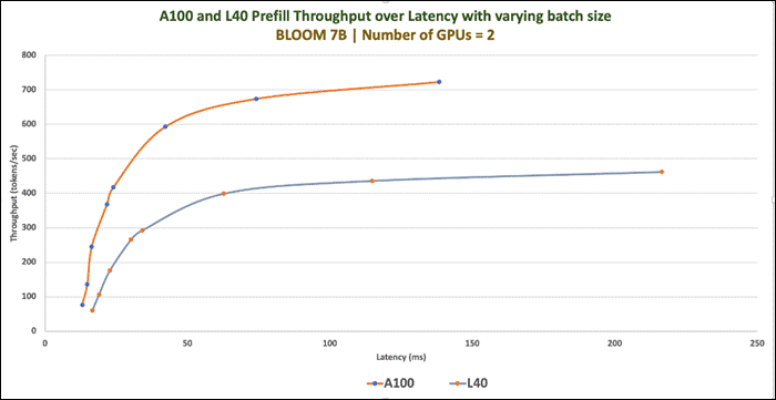
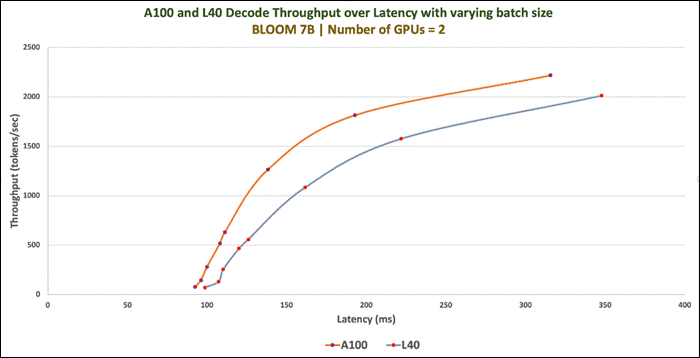
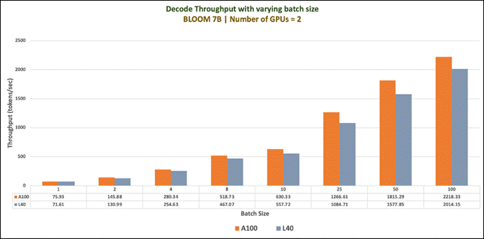
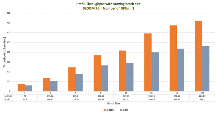
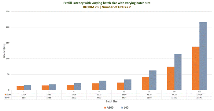
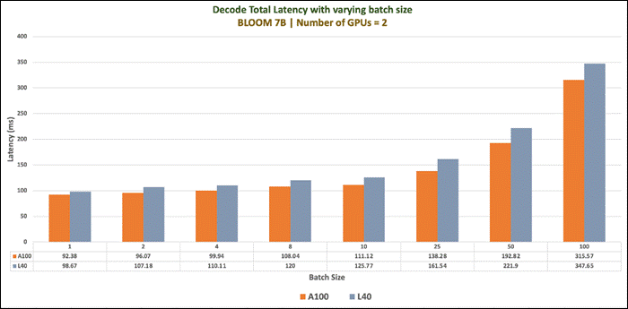
The GALACTICA models are trained on a large-scale scientific corpus. The models are designed to perform scientific tasks, including but not limited to citation prediction, scientific QA, mathematical reasoning, summarization, document generation, molecular property prediction and entity extraction. The models were developed by the Papers with Code team at Meta AI to study the use of language models for the automatic organization of science.
Models were trained with sizes ranging from 125M to 120B parameters. We have considered model size of 30B parameters for validation.
| Model Details |
Scenario |
vGPUs |
Infrastructure |
| facebook/galactica-30b
Size: 30B
Inferencing Server: Text Generation Inference
|
Number of runs: 100
Batch Sie: 1,2,4, 8,10,25,50,100 and 200 |
One and Two A100D-80C |
Red Hat OpenShift 4.14 deployed on VMware vSphere
Resources of worker node with GPUs: CPUs: 128 Cores Per Socket: 64 Memory: 128GB Disk Size: 700GB |
Model Download
Model can be downloaded from Hugging Face, here: https://huggingface.co/facebook/galactica-30b
Test Results
Benchmark was run with different batch sizes(1,2,4,8,10,25,50 and 100). Tests focused on performance comparison between 1 X A100D-80C and 2 X A100D-80C virtual GPUs. Separate tests were run one and two vGPUs. Prefill Latency, Prefill Throughput, Decode Total Latency, Decode Token Latency, Decode Throughput were measured.
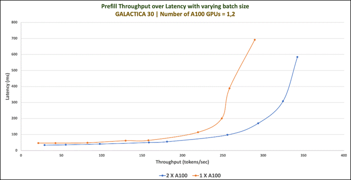
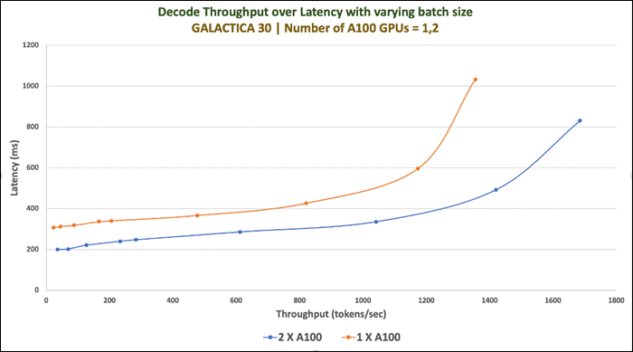
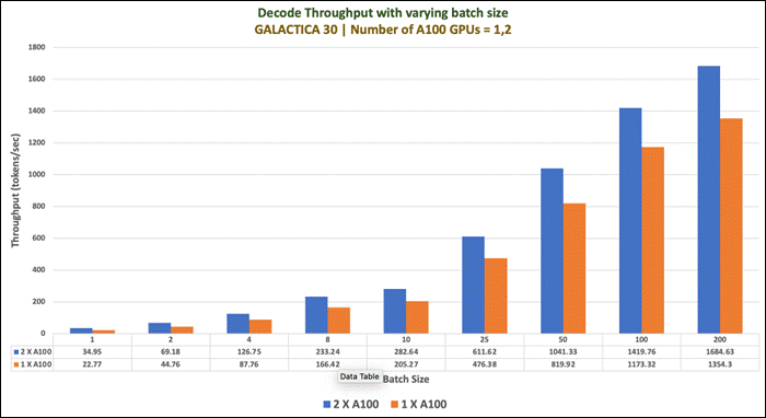
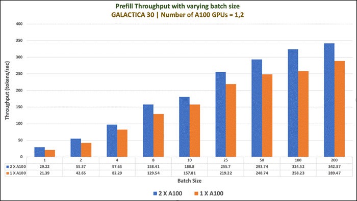
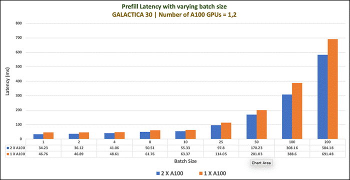
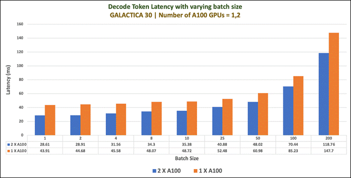
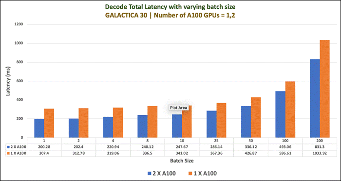
Falcon-40B is a 40B parameters causal decoder-only large language model created by Technology Innovation Institute.
It is trained on 1 trillion tokens. The key ingredient for the high quality of the Falcon models is their training data, predominantly based (>80%) on RefinedWeb — a novel massive web dataset based on CommonCrawl. It is made available under the Apache 2.0 license.
| Model Details |
Scenario |
vGPUs |
Infrastructure |
| tiiuae/falcon-40b Model Size: 40B Parameters
Tensor type: BF16
Inferencing Server: Text Generation Inference |
Number of runs: 100
Batch Sie: 1,2,4,8,10,25,50 and 100
|
2 X A100D-80C |
Red Hat OpenShift 4.14 deployed on VMware vSphere
Resources of worker node with GPUs: CPUs: 128 Cores Per Socket: 64 Memory: 128GB Disk Size: 700GB |
Model Download
Model can be downloaded from Hugging Face, here: https://huggingface.co/tiiuae/falcon-40b
Sample Run
Figure 147 is an example of running inference of the Falcon-40B running on 2XA100 GPUs.
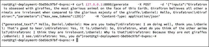
Tests Results
Benchmark was run with different batch sizes (1,2,4,8,10,25,50 and 100). Tests focused on the performance of Falcon-40B with two A100 Virtual GPUs. Prefill Latency, Prefill Throughput, Decode Total Latency, Decode Token Latency, Decode Throughput were measured.
Table 30. Benchmark Test Results
| Model |
Batch Size |
Prefill Latency |
Decode Token Latency |
Decode Total Latency |
Prefill Throughput |
Decode Throughput |
| Falcon-40B |
1 |
36.3 |
32.0 |
224.0 |
27.6 |
31.3 |
| 2 |
37.8 |
33.0 |
230.5 |
52.9 |
60.7 |
|
| 4 |
41.5 |
34.5 |
241.2 |
96.5 |
116.1 |
|
| 8 |
49.9 |
35.3 |
247.2 |
160.4 |
226.6 |
|
| 10 |
52.9 |
35.9 |
251.1 |
189.2 |
278.8 |
|
| 25 |
91.7 |
39.8 |
278.3 |
272.7 |
628.8 |
|
| 50 |
164.6 |
43.6 |
305.1 |
303.9 |
1147.1 |
|
| 100 |
325.3 |
54.4 |
381.0 |
307.5 |
1837.6 |
Maximum GPU utilization was achieved when the inferencing was running as shown in Figure 148.
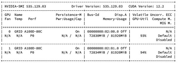
Defog's SQLCoder is a large language model for converting natural language questions to SQL queries. SQLCoder is fine-tuned on a base StarCoder model.
Defog was trained on more than 20,000 human-curated questions. These questions were based on 10 different schemas. None of the schemas in the training data were included in our evaluation framework.
| Model Details |
Scenario |
vGPUs |
Infrastructure |
| defog/sqlcoder2 Model Size: 15B Parameters
Tensor type: BF16
Inferencing Server: Text Generation Inference |
Number of runs: 100
Batch Sie: 1,2,4,8,10,25,50 and 100
|
2 X A100D-80C |
Red Hat OpenShift 4.14 deployed on VMware vSphere
Resources of worker node with GPUs: CPUs: 128 Cores Per Socket: 64 Memory: 128GB Disk Size: 700GB |
Model Download
Model can be downloaded from Hugging Face, here: https://huggingface.co/defog/sqlcoder2
Sample Run
Figure 149 is an example of running inference of the SQLCoder running on 2XA100 GPUs.
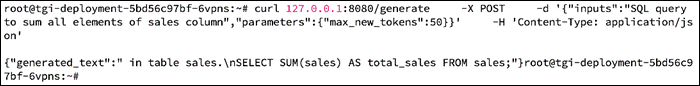
Tests Results
Benchmark was run with different batch sizes(1,2,4,8,10,25,50 and 100). Tests focused on the performance of SQLCoder with two A100 Virtual GPUs. Prefill Latency, Prefill Throughput, Decode Total Latency, Decode Token Latency, Decode Throughput were measured.
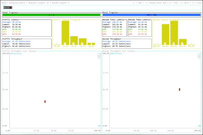
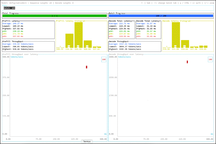
Code Llama is a collection of pretrained and fine-tuned generative text models ranging in scale from 7 billion to 34 billion parameters. This is the repository for the 34B Python specialist version in the Hugging Face Transformers format. This model is designed for general code synthesis and understanding.
Table 32. Multiple versions are available
| Base Model |
Python |
Instruct |
Model Parameters |
| codellama/CodeLlama-7b-hf |
codellama/CodeLlama-7b-Python-hf |
codellama/CodeLlama-7b-Instruct-hf |
7B |
| codellama/CodeLlama-13b-hf |
codellama/CodeLlama-13b-Python-hf |
codellama/CodeLlama-13b-Instruct-hf |
13B |
| codellama/CodeLlama-34b-hf |
codellama/CodeLlama-34b-Python-hf |
codellama/CodeLlama-34b-Instruct-hf |
34B |
| Model Details |
Scenario |
vGPUs |
Infrastructure |
|
Model Size: 15B Parameters
Tensor type: BF16
Inferencing Server: Text Generation Inference |
Number of runs: 100
Batch Sie: 1,2,4,8,10,25,50 and 100
|
2 X A100D-80C |
Red Hat OpenShift 4.14 deployed on VMware vSphere
Resources of worker node with GPUs: CPUs: 128 Cores Per Socket: 64 Memory: 128GB Disk Size: 700GB |
Model Download
Model can be downloaded from Hugging Face, here: https://huggingface.co/codellama
Sample Run
The figure below is an example of running inference of the CodeLlama-34b-Python-hf running on 2XA100 GPUs.
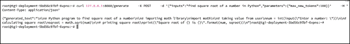
Maximum GPU Utilization is provided below:
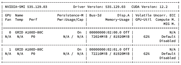
Tests Results
Benchmark was run with different batch sizes(1,2,4,8,10,25,50 and 100). Tests focused on the performance of multiple versions of CodeLlama 34B with two A100 Virtual GPUs. Prefill Latency, Prefill Throughput, Decode Total Latency, Decode Token Latency, Decode Throughput were measured.
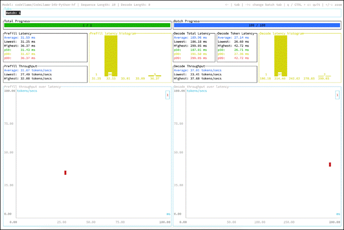
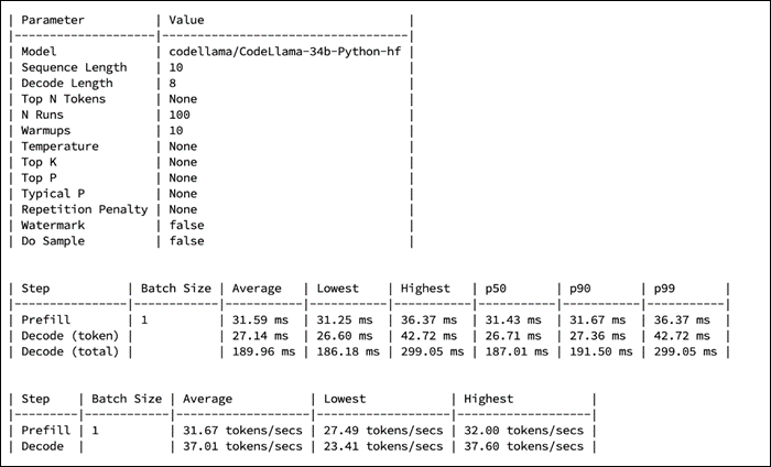
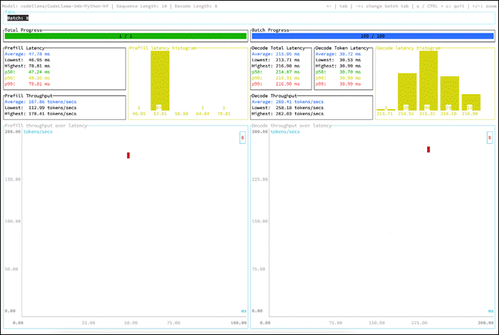
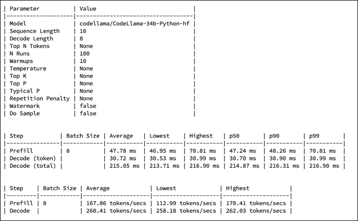
GPT-NeoX-20B is a 20 billion parameter autoregressive language model trained on the Pile using the GPT-NeoX library. Its architecture intentionally resembles that of GPT-3 and is almost identical to that of GPT-J- 6B. Its training dataset contains a multitude of English-language texts, reflecting the general-purpose nature of this model.
| Model Details |
Scenario |
vGPUs |
Infrastructure |
| EleutherAI/gpt-neox-20b Size: 20.7B Parameters Tensor type: FP16 U8
Inferencing Server: Text Generation Inference
|
Number of runs: 100
Batch Sie: 1,2,4,8,10,25,50 and 100
|
2 X L40-48C
|
Red Hat OpenShift 4.14 deployed on VMware vSphere
Resources of worker node with GPUs: CPUs: 128 Cores Per Socket: 64 Memory: 128GB Disk Size: 700GB |
Model Download
Model can be downloaded from Hugging Face, here: https://huggingface.co/EleutherAI/gpt-neox-20b
Sample Run
Figure 156 is an example of running inference of the GPT-NeoX-20B running with one X L40-48C GPUs for the input “Where can I find Giraffes?”
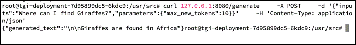
Maximum GPU utilization when above inferencing was running is provided in Figure 157.
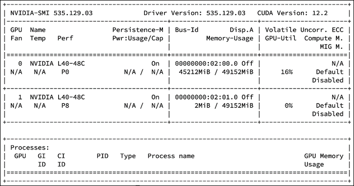
Tests Results
Benchmark was run with different batch sizes(1,2,4,8,10,25,50 and 100). Tests focused on the performance of GPT-NeoX-20B with one and two L40-48C Virtual GPUs. Prefill Latency, Prefill Throughput, Decode Total Latency, Decode Token Latency, Decode Throughput were measured.
Table 35. Benchmark Test Results
|
GPUs |
Batch Size |
Prefill Latency |
Decode Token Latency |
Decode Total Latency |
Prefill Throughput |
Decode Throughput |
| GPT-NeoX (20B) with One X L40
|
1 |
57.1 |
51.5 |
360.6 |
17.5 |
19.4 |
| 2 |
57.2 |
55.9 |
391.1 |
34.7 |
35.8 |
|
| 4 |
60.3 |
57.4 |
401.8 |
66.4 |
69.8 |
|
| 8 |
68.8 |
57.7 |
404.0 |
116.8 |
138.7 |
|
| 10 |
75.9 |
58.8 |
411.9 |
136.1 |
170.2 |
|
| 25 |
123.1 |
59.2 |
414.3 |
203.3 |
422.5 |
|
| 50 |
232.1 |
63.0 |
441.1 |
217.5 |
793.6 |
|
| 100 |
410.9 |
77.5 |
542.7 |
243.4 |
1290.0 |
|
| 200 |
Out of available cache blocks |
|||||
| GPT-NeoX (20B) with Two X L40
|
1 |
33.7 |
28.9 |
202.0 |
29.7 |
34.7 |
| 2 |
35.4 |
31.7 |
222.0 |
56.5 |
63.2 |
|
| 4 |
38.2 |
32.8 |
229.4 |
104.8 |
122.1 |
|
| 8 |
45.6 |
33.3 |
233.2 |
175.5 |
240.1 |
|
| 10 |
47.7 |
33.7 |
236.0 |
210.7 |
296.6 |
|
| 25 |
83.1 |
37.3 |
261.3 |
300.7 |
669.9 |
|
| 50 |
148.2 |
41.6 |
291.0 |
337.4 |
1203.2 |
|
| 100 |
277.8 |
50.1 |
350.9 |
360.0 |
1995.1 |
|
| 200 |
512.3 |
82.2 |
575.6 |
390.5 |
2432.4 |
|
MPT-30B is a decoder-style transformer pretrained from scratch on 1T tokens of English text and code. This model was trained by MosaicML.
MPT-30B is part of the family of Mosaic Pretrained Transformer (MPT) models, which use a modified transformer architecture optimized for efficient training and inference.
The following models are finetuned on MPT-30B:
● MPT-30B-Instruct: a model for long-form instruction following (especially summarization and question-answering). Built by finetuning MPT-30B on several carefully curated datasets.
● MPT-30B-Chat: a chatbot-like model for dialogue generation. Built by finetuning MPT-30B on ShareGPT-Vicuna, Camel-AI, GPTeacher, Guanaco, Baize, and some generated datasets.
| Model Details |
Scenario |
vGPUs |
Infrastructure |
| mosaicml/mpt-30b Size: 30B Tensor type: BF16
Inferencing Server: Text Generation Inference
|
Number of runs: 100
Batch Sie: 1,2,4,8,10,25,50 and 100
|
2 X A100
|
Red Hat OpenShift 4.14 deployed on VMware vSphere
Resources of worker node with GPUs: CPUs: 128 Cores Per Socket: 64 Memory: 128GB Disk Size: 700GB |
Model Download
Model can be downloaded from Hugging Face, here: https://huggingface.co/mosaicml/mpt-30b
Sample Run
Figure 158 is an example of running inference of the MPT-30B running with one X A100 GPUs for the input “Here is a recipe for vegan banana bread.”
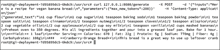
Tests Results
Benchmark was run with different batch sizes(1,2,4,8,10,25,50 and 100). Tests focused on the performance of MPT-30B with one and two A100 Virtual GPUs. Prefill Latency, Prefill Throughput, Decode Total Latency, Decode Token Latency, Decode Throughput were measured.
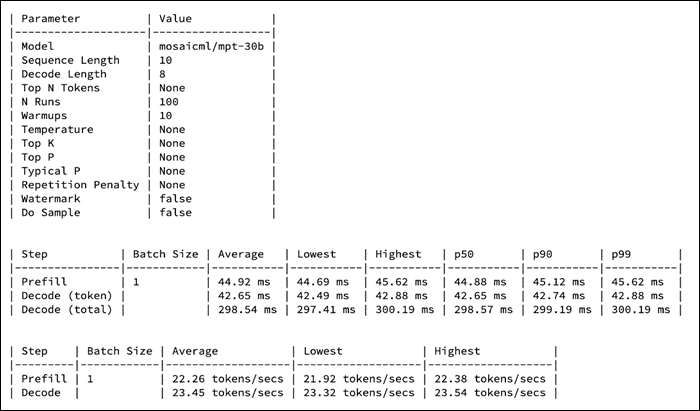
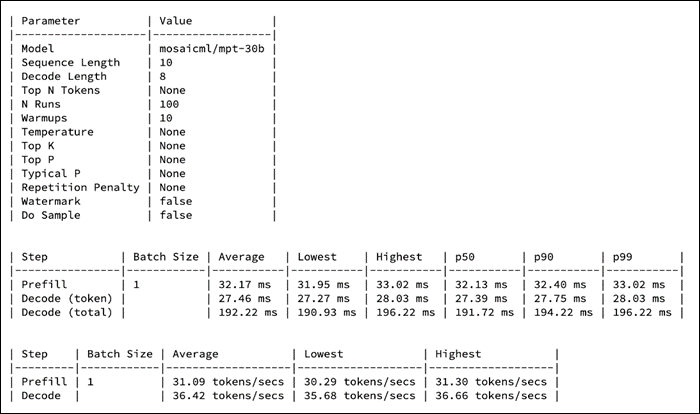
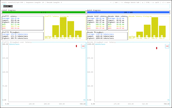
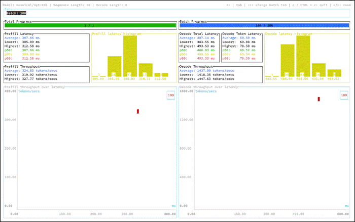
OPT : Open Pre-trained Transformer Language Models
Pre-trained Transformers (OPT) is a suite of decoder-only pre-trained transformers ranging from 125M to 175B parameters.
OPT was predominantly pretrained with English text, but a small amount of non-English data is still present within the training corpus via CommonCrawl. The model was pretrained using a causal language modeling (CLM) objective. OPT belongs to the same family of decoder-only models like GPT-3. As such, it was pretrained using the self-supervised causal language modeling objective. For evaluation, OPT follows GPT-3 by using their prompts and overall experimental setup.
| Model Details |
Scenario |
vGPUs |
Infrastructure |
| facebook/opt-2.7b Size: 2.7B Parameters Tensor type: BF16
Inferencing Server: Text Generation Inference
|
Number of runs: 100
Batch Sie: 1,2,4,8,10,25,50 and 100
|
2 X L40-48C
|
Red Hat OpenShift 4.14 deployed on VMware vSphere
Resources of worker node with GPUs: CPUs: 128 Cores Per Socket: 64 Memory: 128GB Disk Size: 700GB |
Model Download
Model can be downloaded from Hugging Face, here: https://huggingface.co/facebook/opt-2.7b
Sample Run
Figure 163 is an example of running inference of the OPT-2.7B running with one X L40-48C GPUs for the input “What is the capital of India?”
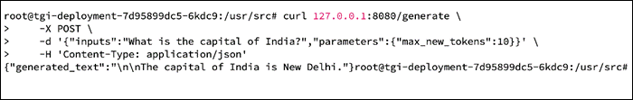
Maximum GPU utilization is achieved when the provided inferencing was running as shown in Figure 164.
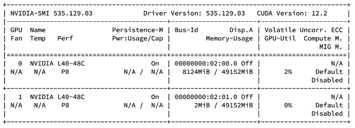
The following are the key factors for sizing infrastructure for Generative AI inferencing.
Model Specifications
● Model Architecture: Understand the architecture of the language model, including the number of layers, attention heads, and parameters.
● Token Embedding Size: Larger embedding sizes can significantly impact memory requirements.
Hardware Acceleration
● Mixed Precision: Explore mixed-precision training and inference to leverage hardware capabilities efficiently.
Memory Requirements
● Model Size: Large language models can have substantial memory requirements. Ensure sufficient GPU memory for both the model and input sequences.
● Sequence Length: Consider the maximum sequence length the model can handle and its impact on memory usage.
Batching and Parallelization
● Batch Size: Experiment with batch sizes. Larger batch sizes can improve throughput but may increase memory requirements.
● Data Parallelism: Implement data parallelism to distribute inference across multiple devices, if necessary.
Latency and Throughput
● Latency Requirements: Language models often have real-time constraints, especially in interactive applications. Minimize latency based on use case.
● Throughput Targets: Determine the required throughput in terms of processed tokens or sequences per second.
Scalability
● Model Parallelism: Consider model parallelism if the model size exceeds available GPU memory, distributing parts of the model across multiple GPUs.
● Infrastructure Scaling: Design for horizontal scalability to handle increased demand.
Redundancy and High Availability
● Checkpointing: Implement regular model checkpointing to recover from failures without losing training progress.
● Replication: Use redundant systems to ensure high availability during inference.
Network Considerations
● Bandwidth: Assess the network bandwidth required for transferring large model parameters between devices.
● Inter-Device Communication: Optimize communication patterns between devices to minimize latency.
Storage Requirements
● Model Storage: Choose storage solutions capable of efficiently loading large model parameters.
● Data Storage: Assess storage needs for input data and any intermediate results.
Containerization and Orchestration
● Containerization: Deploy the language model within containers for easier management and consistency across different environments.
● Orchestration: Use container orchestration tools like Kubernetes for managing and scaling the deployment efficiently.
Middleware and Serving Frameworks
● Serving Framework: Choose a serving framework optimized for deploying large language models, such as TensorFlow Serving, Triton Inference Server, or others.
● Middleware: Implement middleware for handling communication between clients and the deployed model, ensuring compatibility with your application's requirements.
Monitoring and Optimization
● Resource Monitoring: Employ monitoring tools to track GPU utilization, memory usage, and other relevant metrics.
● Dynamic Optimization: Optimize parameters dynamically based on real-time performance metrics.
Security
● Data Protection: Implement measures to secure input and output data, especially if it involves sensitive information.
● Model Security: Protect large language models from adversarial attacks and unauthorized access.
Visibility and Monitoring
This chapter contains the following:
● Cisco Intersight Workload Optimizer
● Monitoring GPU Metrics from VMware vCenter and ESXi Host
● OpenShift Dashboard for GPUs
It is critical to gain complete visibility into the entire stack, including Physical infrastructure [Compute, Storage and Network], Virtualized infrastructure, OpenShift clusters and application. It helps to gain insight into infrastructure bottlenecks and factors that increase costs. and ensure the performance for model inferencing and applications making use of it.
Cisco Intersight Workload Optimizer
Flash storage addresses many of the performance issues for I/O-intensive applications deployed in virtualized data centers. However, problems or bottlenecks can also exist in the compute and network layers, affecting overall application performance. Eliminating performance bottlenecks in just one layer will not expose performance problems in other data center layers. You need to address performance issues across the entire stack, including the compute, network, and storage layers.
With Cisco Intersight Workload Optimizer and FlashStack, enterprises can solve their most important virtualization challenges, improve infrastructure performance, and make full use of their investment in high-performance, high-efficiency Infrastructure.
Cisco Intersight Workload Optimizer makes it easy to see what is happening in your environment and understand how that affects your applications. You can do the following:
● Gain visibility into the health, use, and performance of your infrastructure stack. Your operations and application teams can discover application and infrastructure interdependencies to make more informed decisions about how to apply and use IT resources.
● Get insight into infrastructure bottlenecks and factors that increase costs. Intelligent analytics stitch together each layer of the application and infrastructure stack, allowing resourcing decisions to be tied to application demand and relevant policies and constraints while factoring in available capacity.
● Trust actions that continuously optimize your infrastructure to deliver application performance. Specific real-time actions ensure that your workloads get the resources they need when they need them for placement, scaling, and capacity. You can automate the software’s decisions to match your level of comfort: recommend (view only), manual (select and apply), or automated (implemented in real time by software).
In Cisco Intersight Workload Optimizer, if you navigate to Workload Optimization > Overview, you can see the consolidated supply chain from Cisco Intersight Workload Optimizer. Market abstraction is fundamental to Workload Optimizer, which models all the elements of applications and infrastructure into a supply chain of buyers and sellers and show the relationships among the various elements. This supply chain represents the flow of resources from the data center, through the physical tiers of your environment, into the virtual tier, and out to the cloud. By managing relationships between these buyers and sellers, Workload Optimizer provides closed-loop management of resources, from the data center through to the application.
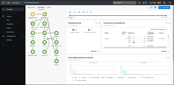
You can select any resource to get a detailed view of the resource, its health status. Also, Workload Optimizer makes multiple recommendations for workloads to perform at the best possible cost while maintaining compliance. It has actions you can take on various elements: scale up or down, delete, start, or buy, make a placement, make configuration changes, and stop action.
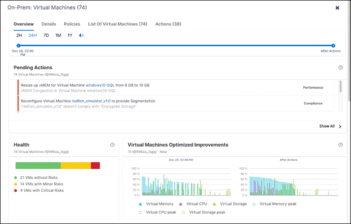
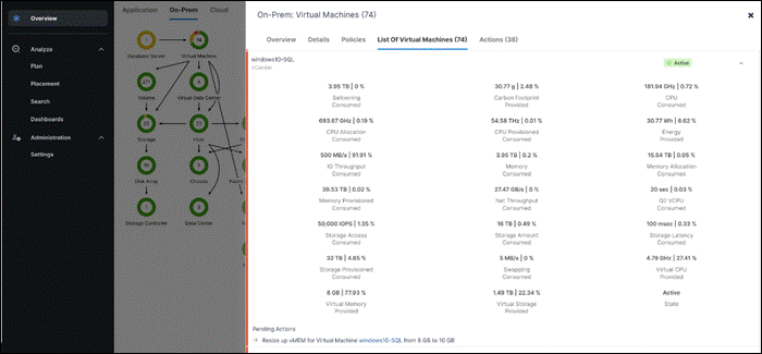
Monitoring GPU Metrics from VMware vCenter and ESXi Host
In VCenter, various metrics data can be viewed for the physical GPUs like Memory Usage, Memory Used, Temperature and Utilization.
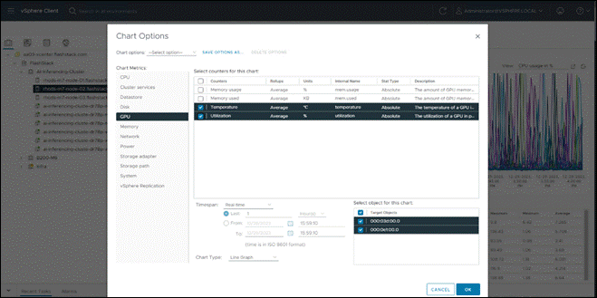
Figure 168 shows the GPU Temperature and GPU Utilization for 2 physical GPUs.
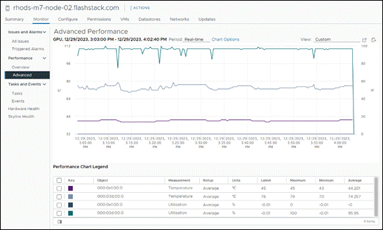
After the NVIDIA AI Enterprise Host Software is installed on the host server, it provides a CLI tools called ‘nvidia-smi’ which provided various information of the GPU.
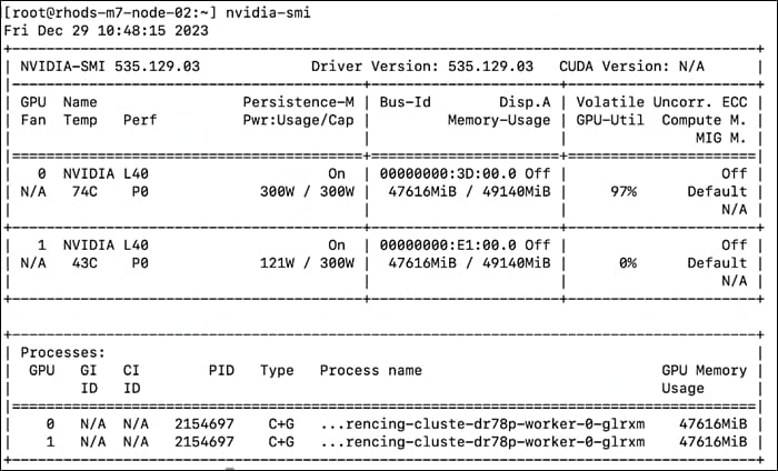
Nvidia-smi has various options to obtain more detailed information.
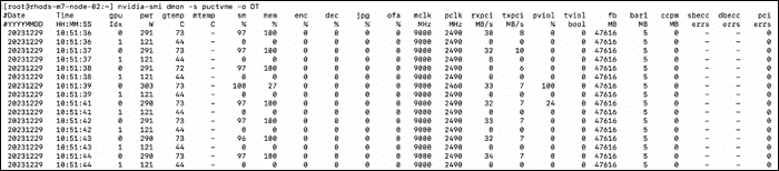
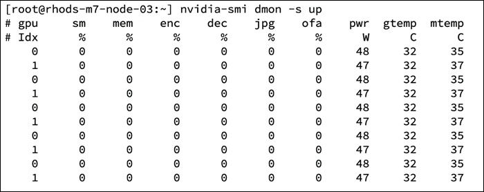
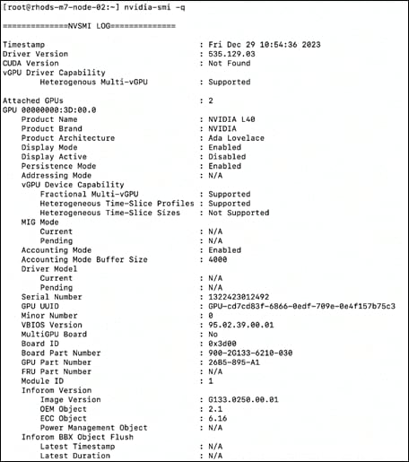
In OpenShift, The GPU Operator exposes GPU telemetry for Prometheus by using the NVIDIA DCGM Exporter. These metrics can be visualized using a monitoring dashboard based on Grafana.
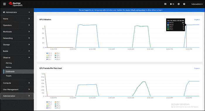
Individual queries can be constructed to explore the metrics. In Figure 174, a query is sent to get GPU Framebuffer Mem Used from all the virtual GPUs in the cluster.
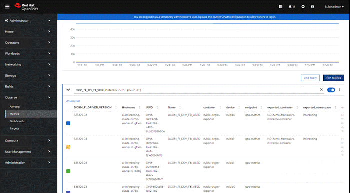
In OpenShift, Grafana instances provided with the monitoring stack (and its dashboards) are read-only. To solve this problem, we can use the community-powered Grafana operator provided by OperatorHub in OpenShift and create custom dashboard.
Figure 175 shows different panels for GPU Metrics, OpenShift Infrastructure and OpenShift Cluster metrics all consolidated into a dashboard.
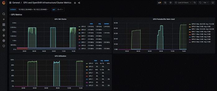
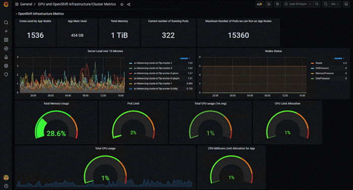
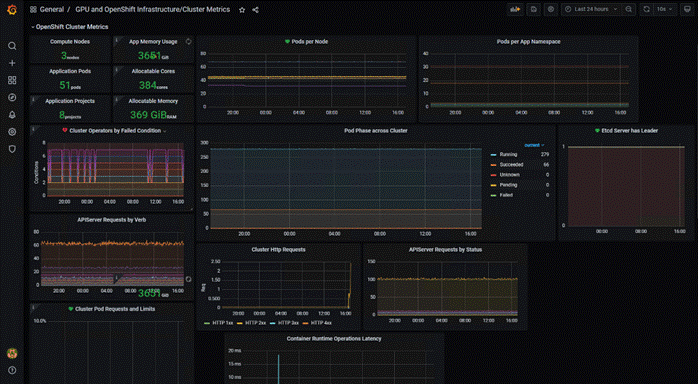
Conclusion
This validated solution stands as a valuable resource for navigating the complexities of Generative AI deployment in real-world enterprise environments.
This Cisco Validated Design for FlashStack for Generative AI Inferencing Design Guide provides a foundational reference architecture for Generative AI inferencing in enterprises. The document explored various generative AI models deployed on inferencing servers/backends focusing on deployment of Large Language Models and other Generative AI models with consistent management and operational experiences.
The infrastructure is designed using the Cisco UCS X-Series modular platform based FlashStack Datacenter, managed through Cisco Intersight. Deployment involves Red Hat OpenShift Container Platform clusters on VMware vSphere, running on Cisco UCS X210c M7 compute nodes equipped with NVIDIA GPUs. The NVIDIA AI Enterprise software powers the inferencing workflow, while Portworx Enterprise Storage, backed by Pure Storage Flash Array and Flash Blade, ensures cloud-native storage for model repositories and other services.
Automation facilitated by Red Hat Ansible, provides Infrastructure as Code (IaC) for accelerating deployments.
The FlashStack solution is a validated approach for deploying Cisco and Pure Storage technologies in an enterprise data center. This release of the FlashStack VSI solution brings the following capabilities:
● Fourth generation Intel Xeon Scalable processors with Cisco UCS X210 M7, C220 M7 and C240 M7 servers, enabling up to 60 cores per processor and 8TB of DDR-4800 DIMMs.
● Sustainability monitoring and optimizations to meet Enterprise ESG targets that include power usage monitoring features across all layers of the stack and utilizing the Cisco UCS X-Series advanced power and cooling policies.
● FA Unified Block and File consisting of FC-SCSI, FC-NVMe, iSCSI, NVMe-TCP, NVMe-RoCEv2 as well as NFS storage from Pure Storage.
● FlashBlade//S, a high-performance consolidated storage platform for both file (with native SMB and NFS support) and object workloads, delivering a simplified experience for infrastructure and data management.
● VMware vSphere 8.0 innovations.
Cisco Intersight continues to deliver features that simplify enterprise IT operations, with services and workflows that provide complete visibility and operations across all elements of FlashStack datacenter. Also, Cisco Intersight integration with VMware vCenter and Pure Storage FlashArray extends these capabilities and enable workload optimization to all layers of the FlashStack infrastructure.
Paniraja Koppa, Technical Marketing Engineer, Cisco Systems, Inc.
Paniraja Koppa is a member of the Cisco Unified Computing System (Cisco UCS) solutions team. He has over 15 years of experience designing, implementing, and operating solutions in the data center. In his current role, he works on design and development, best practices, optimization, automation and technical content creation of compute and hybrid cloud solutions. He also worked as technical consulting engineer in the data center virtualization space. Paniraja holds a master’s degree in computer science. He has presented several papers at international conferences and speaker at events like Cisco Live US and Europe, Open Infrastructure Summit, and other partner events.
JB Blair, Senior Solutions Architect, NVIDIA
JB Blair is a Senior Solutions Architect with over a decade of experience in software engineering, networking, and cybersecurity. Using these skills, he helps bring innovative NVIDIA technologies in GPU and DPU acceleration to product, development, and engineering teams. He distinguishes himself by integrating Generative AI to help build innovative solutions with customers and partners.
Acknowledgements
For their support and contribution to the design, validation, and creation of this Cisco Validated Design, the author would like to thank:
● Chris O'Brien, Senior Director, Cisco Systems, Inc.
● Tushar Patel, Distinguished TME, Cisco Systems, Inc.
● John George, Technical Marketing Engineer, Cisco Systems, Inc.
● Archana Sharma, Technical Marketing Engineer, Cisco Systems, Inc.
● Hardik Patel, Technical Marketing Engineer, Cisco Systems, Inc.
● Rohit Mittal, Product Manager, Cisco Systems, Inc.
● Rajendra Yogendra, Technical Marketing Engineer, Cisco Systems, Inc.
● Sindhu Sudhir, Technical Marketing Engineer, Cisco Systems, Inc.
● Vijay Kulari, Senior Solutions Architect, Pure Storage, Inc.
● Craig Waters, Technical Director, Pure Storage, Inc.
● Philip Niman, Alliance Development Manager, Pure Storage, Inc.
● Sicong Ji, Cisco-NVIDIA Partnership, NVIDIA
● Vinh Nguyen, Data Scientist, NVIDIA
● Jia Dai, Senior MLOps Solution Architect, NVIDIA
● Terry Kong, Senior Deep Learning Algorithm Engineer, NVIDIA
● Robert Clark, Senior Deep Learning Algorithm Engineer, NVIDIA
● Max Xu, Senior Solution Engineer, NVIDIA
● Dhaval Dave, Senior Enterprise Solutions Engineer, NVIDIA
GitHub repository for Cisco UCS solutions: https://github.com/ucs-compute-solutions/
Cisco Intersight: https://www.intersight.com
Cisco Intersight Managed Mode: https://www.cisco.com/c/en/us/td/docs/unified_computing/Intersight/b_Intersight_Managed_Mode_Configuration_Guide.html
Cisco Unified Computing System: http://www.cisco.com/en/US/products/ps10265/index.html
Cisco Nexus 9000 Series Switches: http://www.cisco.com/c/en/us/products/switches/nexus-9000-series-switches/index.html
Cisco MDS 9132T Switches: https://www.cisco.com/c/en/us/products/collateral/storage-networking/mds-9100-series-multilayer-fabric-switches/datasheet-c78-739613.html
Pure Storage FlashArray//X: https://www.purestorage.com/products/nvme/flasharray-x.html
Pure Storage FlashBlade//S: https://www.purestorage.com/products/unstructured-data-storage.html
Pure Storage FlashArray Compatibility Matrix: https://support.purestorage.com/FlashArray/Getting_Started_with_FlashArray/FlashArray_Compatibility_Matrix
Pure Storage FlashBlade Compatibility Matrix: https://support.purestorage.com/FlashBlade/Getting_Started_with_FlashBlade/FlashBlade_Compatibility_Matrix
FlashStack Compatibility Matrix: https://support.purestorage.com/FlashStack/Product_Information/FlashStack_Compatibility_Matrix
VMware vCenter Server: http://www.vmware.com/products/vcenter-server/overview.html
VMware vSphere: https://www.vmware.com/products/vsphere
Cisco UCS Hardware Compatibility Matrix: https://ucshcltool.cloudapps.cisco.com/public/
VMware and Cisco Unified Computing System: http://www.vmware.com/resources/compatibility
Pure Storage Interoperability Matrix (requires a support account): https://support.purestorage.com/FlashArray/Getting_Started/Compatibility_Matrix
Pure Storage FlashStack Compatibility Matrix (requires a support account): https://support.purestorage.com/FlashStack/Product_Information/FlashStack_Compatibility_Matrix
For comments and suggestions about this guide and related guides, join the discussion on Cisco Community at https://cs.co/en-cvds.
CVD Program
ALL DESIGNS, SPECIFICATIONS, STATEMENTS, INFORMATION, AND RECOMMENDATIONS (COLLECTIVELY, "DESIGNS") IN THIS MANUAL ARE PRESENTED "AS IS," WITH ALL FAULTS. CISCO AND ITS SUPPLIERS DISCLAIM ALL WARRANTIES, INCLUDING, WITHOUT LIMITATION, THE WARRANTY OF MERCHANTABILITY, FITNESS FOR A PARTICULAR PURPOSE AND NONINFRINGEMENT OR ARISING FROM A COURSE OF DEALING, USAGE, OR TRADE PRACTICE. IN NO EVENT SHALL CISCO OR ITS SUPPLIERS BE LIABLE FOR ANY INDIRECT, SPECIAL, CONSEQUENTIAL, OR INCIDENTAL DAMAGES, INCLUDING, WITHOUT LIMITATION, LOST PROFITS OR LOSS OR DAMAGE TO DATA ARISING OUT OF THE USE OR INABILITY TO USE THE DESIGNS, EVEN IF CISCO OR ITS SUPPLIERS HAVE BEEN ADVISED OF THE POSSIBILITY OF SUCH DAMAGES.
THE DESIGNS ARE SUBJECT TO CHANGE WITHOUT NOTICE. USERS ARE SOLELY RESPONSIBLE FOR THEIR APPLICATION OF THE DESIGNS. THE DESIGNS DO NOT CONSTITUTE THE TECHNICAL OR OTHER PROFESSIONAL ADVICE OF CISCO, ITS SUPPLIERS OR PARTNERS. USERS SHOULD CONSULT THEIR OWN TECHNICAL ADVISORS BEFORE IMPLEMENTING THE DESIGNS. RESULTS MAY VARY DEPENDING ON FACTORS NOT TESTED BY CISCO.
CCDE, CCENT, Cisco Eos, Cisco Lumin, Cisco Nexus, Cisco StadiumVision, Cisco TelePresence, Cisco WebEx, the Cisco logo, DCE, and Welcome to the Human Network are trademarks; Changing the Way We Work, Live, Play, and Learn and Cisco Store are service marks; and Access Registrar, Aironet, AsyncOS, Bringing the Meeting To You, Catalyst, CCDA, CCDP, CCIE, CCIP, CCNA, CCNP, CCSP, CCVP, Cisco, the Cisco Certified Internetwork Expert logo, Cisco IOS, Cisco Press, Cisco Systems, Cisco Systems Capital, the Cisco Systems logo, Cisco Unified Computing System (Cisco UCS), Cisco UCS B-Series Blade Servers, Cisco UCS C-Series Rack Servers, Cisco UCS S-Series Storage Servers, Cisco UCS X-Series, Cisco UCS Manager, Cisco UCS Management Software, Cisco Unified Fabric, Cisco Application Centric Infrastructure, Cisco Nexus 9000 Series, Cisco Nexus 7000 Series, Cisco Prime Data Center Network Manager, Cisco NX-OS Software, Cisco MDS Series, Cisco Unity, Collaboration Without Limitation, EtherFast, EtherSwitch, Event Center, Fast Step, Follow Me Browsing, FormShare, GigaDrive, HomeLink, Internet Quotient, IOS, iPhone, iQuick Study, LightStream, Linksys, MediaTone, MeetingPlace, MeetingPlace Chime Sound, MGX, Networkers, Networking Academy, Network Registrar, PCNow, PIX, PowerPanels, ProConnect, ScriptShare, SenderBase, SMARTnet, Spectrum Expert, StackWise, The Fastest Way to Increase Your Internet Quotient, TransPath, WebEx, and the WebEx logo are registered trade-marks of Cisco Systems, Inc. and/or its affiliates in the United States and certain other countries. (LDW_P4)
All other trademarks mentioned in this document or website are the property of their respective owners. The use of the word partner does not imply a partnership relationship between Cisco and any other company. (0809R)