- Preface
- Overview
- Using the Command-Line Interface
- Assigning the Switch IP Address and Default Gateway
- Configuring Cisco IOS Configuration Engine
- Administering the Switch
- Configuring Switch Alarms
- Configuring SDM Templates
- Configuring Switch-Based Authentication
- Configuring IEEE 802.1x Port-Based Authentication
- Configuring Interface Characteristics
- Configuring Command Macros
- Configuring VLANs
- Configuring Private VLANs
- Configuring IEEE 802.1Q and Layer 2 Protocol Tunneling
- Configuring STP
- Configuring MSTP
- Configuring Optional Spanning-Tree Features
- Configuring Resilient Ethernet Protocol
- Configuring Flex Links and the MAC Address-Table Move Update Feature
- Configuring DHCP Features and IP Source Guard
- Configuring Dynamic ARP Inspection
- Configuring IGMP Snooping and MVR
- Configuring Port-Based Traffic Control
- Configuring CDP
- Configuring LLDP and LLDP-MED
- Configuring UDLD
- Configuring SPAN and RSPAN
- Configuring RMON
- Configuring System Message Logging
- Configuring SNMP
- Configuring Embedded Event Manager
- Configuring Network Security wit
- Configuring Control-Plane Security
- Configuring QoS
- Configuring EtherChannels and Link State Tracking
- Configuring IP Unicast Routing
- Configuring IPv6 Unicast Routing
- Configuring IPv6 MLD Snooping
- Configuring IPv6 ACLs
- Configuring HSRP, VRRP, and GLBP
- Configuring Cisco IOS IP SLAs Operations
- Configuring Enhanced Object Tracking
- Configuring Ethernet OAM, CFM, and E-LMI
- Configuring Y.1731 Performance Monitoring
- Configuring IP Multicast Routing
- Configuring MSDP
- Troubleshooting
- Configuring Online Diagnostics
- Working with the Cisco IOS File System, Configuration Files, and Software Images
- Unsupported Commands in Cisco IOS Release 12.2(58)EX
- Index
Cisco ME 3400E Ethernet Access Switch Software Configuration Guide, Cisco IOS Release 12.2(58)EX
Bias-Free Language
The documentation set for this product strives to use bias-free language. For the purposes of this documentation set, bias-free is defined as language that does not imply discrimination based on age, disability, gender, racial identity, ethnic identity, sexual orientation, socioeconomic status, and intersectionality. Exceptions may be present in the documentation due to language that is hardcoded in the user interfaces of the product software, language used based on RFP documentation, or language that is used by a referenced third-party product. Learn more about how Cisco is using Inclusive Language.
- Updated:
- March 21, 2015
Chapter: Configuring Ethernet OAM, CFM, and E-LMI
- Understanding Ethernet CFM
- Configuring Ethernet CFM
- Default Ethernet CFM Configuration
- Ethernet CFM Configuration Guidelines
- Configuring the CFM Domain
- Configuring Ethernet CFM Crosscheck
- Configuring Static Remote MEP
- Configuring a Port MEP
- Configuring SNMP Traps
- Configuring Fault Alarms
- Configuring IP SLAs CFM Operation
- Configuring CFM on C-VLAN (Inner VLAN)
Configuring Ethernet OAM, CFM, and E-LMI
Ethernet Operations, Administration, and Maintenance (OAM) is a protocol for installing, monitoring, and troubleshooting Ethernet networks to increase management capability within the context of the overall Ethernet infrastructure. The Cisco ME 3400E switch supports IEEE 802.1ag Connectivity Fault Management (CFM), Ethernet Local Management Interface (E-LMI), and IEEE 802.3ah Ethernet OAM discovery, link monitoring, remote fault detection, and remote loopback. It also supports IP Service Level Agreements (SLAs) for CFM, and ITU-T Y.1731 fault management. Ethernet OAM manager controls the interworking between any two of the protocols (CFM, E-LMI, and OAM).
This chapter provides information about configuring CFM, E-LMI, and the Ethernet OAM protocol. It defines the differences between the ratified CFM 802.1ag standard (draft 8.1) and the previous version supported on the switch in Cisco IOS (draft 1.0). It also includes configuration information for CFM ITU-TY.1731 fault management support in this release.
For complete command and configuration information for Ethernet OAM,CFM, E-LMI, and Y.1731, see the Cisco IOS Carrier Ethernet Configuration Guide at this URL:
http://www.cisco.com/en/US/docs/ios/cether/configuration/guide/12_2sr/ce_12_2sr_book.html
For complete syntax of the commands used in this chapter, see the command reference for this release and the Cisco IOS Carrier Ethernet Command Reference at this URL:
http://www.cisco.com/en/US/docs/ios/cether/command/reference/ce_book.html

Note ![]() The Service Diagnostics 2.0 C FM diagnostic script is part of the 12.2(52)SE release. The script is available for download at:
The Service Diagnostics 2.0 C FM diagnostic script is part of the 12.2(52)SE release. The script is available for download at:
http://www.cisco.com/en/US/prod/iosswrel/ps6537/ps6555/ps9424/cisco_ios_service_diagnostics_scripts.html
Refer to the Service Diagnostic 2.0 user guide at:
http://www.cisco.com/en/US/prod/collateral/iosswrel/ps6537/ps6555/ps9424/whitepaper_c11-566741.html
This chapter contains these sections:
•![]() Understanding CFM ITU-T Y.1731 Fault Management
Understanding CFM ITU-T Y.1731 Fault Management
•![]() Configuring Y.1731 Fault Management
Configuring Y.1731 Fault Management
•![]() Managing and Displaying Ethernet CFM Information
Managing and Displaying Ethernet CFM Information
•![]() Understanding the Ethernet OAM Protocol
Understanding the Ethernet OAM Protocol
•![]() Setting Up and Configuring Ethernet OAM
Setting Up and Configuring Ethernet OAM
•![]() Displaying Ethernet OAM Protocol Information
Displaying Ethernet OAM Protocol Information
•![]() Displaying E-LMI and OAM Manager Information
Displaying E-LMI and OAM Manager Information
•![]() Ethernet CFM and Ethernet OAM Interaction
Ethernet CFM and Ethernet OAM Interaction
Understanding Ethernet CFM
Ethernet CFM is an end-to-end per-service-instance (per VLAN) Ethernet layer OAM protocol that includes proactive connectivity monitoring, fault verification, and fault isolation. End-to-end can be provider-edge-to-provider-edge (PE-to-PE) device or customer-edge-to-customer-edge (CE-to-CE) device. Ethernet CFM, as specified by IEEE 802.1ag, is the standard for Layer 2 ping, Layer 2 traceroute, and end-to-end connectivity check of the Ethernet network.
These sections contain conceptual information about Ethernet CFM:
•![]() Maintenance Associations and Maintenance Points
Maintenance Associations and Maintenance Points
•![]() Crosscheck Function and Static Remote MEPs
Crosscheck Function and Static Remote MEPs
CFM Domain
A CFM maintenance domain is a management space on a network that is owned and operated by a single entity and defined by a set of ports internal to it, but at its boundary. You assign a unique maintenance level (from 0 to 7) to define the hierarchical relationship between domains. The larger the domain, the higher the level. For example, as shown in Figure 43-1, a service-provider domain would be larger than an operator domain and might have a maintenance level of 6, while the operator domain maintenance level is 3 or 4.
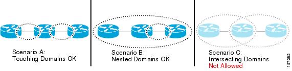
As shown in Figure 43-2, domains cannot intersect or overlap because that would require management by more than one entity, which is not allowed. Domains can touch or nest (if the outer domain has a higher maintenance level than the nested domain). Nesting domains is useful when a service provider contracts with one or more operators to provide Ethernet service. Each operator has its own maintenance domain and the service provider domain is a superset of the operator domains. Maintenance levels of nesting domains should be communicated among the administrating organizations. CFM exchanges messages and performs operations on a per-domain basis.
Figure 43-1 CFM Maintenance Domains
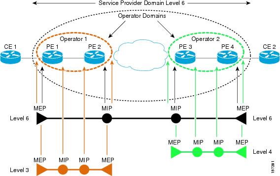
Figure 43-2 Allowed Domain Relationships
Maintenance Associations and Maintenance Points
A maintenance association (MA) identifies a service that can be uniquely identified within the maintenance domain. The CFM protocol runs within a maintenance association. A maintenance point is a demarcation point on an interface that participates in CFM within a maintenance domain. Maintenance points drop all lower-level frames and forward all higher-level frames. There are two types of maintenance points:
•![]() Maintenance end points (MEPs) are points at the edge of the domain that define the boundaries and confine CFM messages within these boundaries. Outward facing or Down MEPs communicate through the wire side (connected to the port). Inward facing or Up MEPs communicate through the relay function side, not the wire side.
Maintenance end points (MEPs) are points at the edge of the domain that define the boundaries and confine CFM messages within these boundaries. Outward facing or Down MEPs communicate through the wire side (connected to the port). Inward facing or Up MEPs communicate through the relay function side, not the wire side.
Note ![]() CFM draft 1 referred to inward and outward-facing MEPs. CFM draft 8.1 refers to up and down MEPs, respectively. This document uses the CFM 8.1 terminology for direction.
CFM draft 1 referred to inward and outward-facing MEPs. CFM draft 8.1 refers to up and down MEPs, respectively. This document uses the CFM 8.1 terminology for direction.
CFM draft 1 supported only up MEPs on a per-port or per-VLAN basis. CFM 802.1ag supports up and down per-VLAN MEPs, as well as port MEPs, which are untagged down MEPs that are not associated with a VLAN. Port MEPs are configured to protect a single hop and used to monitor link state through CFM. If a port MEP is not receiving continuity check messages from its peer (static remote MEP), for a specified interval, the port is put into an operational down state in which only CFM and OAM packets pass through, and all other data and control packets are dropped.
–![]() An up MEP sends and receives CFM frames through the relay function. It drops all CFM frames at its level or lower that come from the wire side, except traffic going to the down MEP. For CFM frames from the relay side, it processes the frames at its level and drops frames at a lower level. The MEP transparently forwards all CFM frames at a higher level, regardless of whether they are received from the relay or wire side. If the port on which MEP is configured is blocked by STP, the MEP can still send or receive CFM messages through the relay function. CFM runs at the provider maintenance level (UPE-to-UPE), specifically with up MEPs at the user network interface (UNI).
An up MEP sends and receives CFM frames through the relay function. It drops all CFM frames at its level or lower that come from the wire side, except traffic going to the down MEP. For CFM frames from the relay side, it processes the frames at its level and drops frames at a lower level. The MEP transparently forwards all CFM frames at a higher level, regardless of whether they are received from the relay or wire side. If the port on which MEP is configured is blocked by STP, the MEP can still send or receive CFM messages through the relay function. CFM runs at the provider maintenance level (UPE-to-UPE), specifically with up MEPs at the user network interface (UNI).
Note ![]() A UNI in the context of CFM and OAM manager is not the same as a UNI port type. The CFM UNI can be a UNI, an enhanced network interface (ENI), or a network node interface (NNI) port type. The switch rate-limits all incoming CFM messages at a fixed rate of 500 frames per second. In CFM draft 1, the control-plane security rate-limited incoming CFM messages only on UNI and ENI port types.
A UNI in the context of CFM and OAM manager is not the same as a UNI port type. The CFM UNI can be a UNI, an enhanced network interface (ENI), or a network node interface (NNI) port type. The switch rate-limits all incoming CFM messages at a fixed rate of 500 frames per second. In CFM draft 1, the control-plane security rate-limited incoming CFM messages only on UNI and ENI port types.
–![]() A down MEP sends and receives CFM frames through the wire connected to the port on which the MEP is configured. It drops all CFM frames at its level or lower that come from the relay side. For CFM frames from the wire side, it processes all CFM frames at its level and drops CFM frames at lower levels except traffic going to the other lower-level down MEP. The MEP transparently forwards all CFM frames at a higher level, regardless of whether they are received from the relay or through the wire.
A down MEP sends and receives CFM frames through the wire connected to the port on which the MEP is configured. It drops all CFM frames at its level or lower that come from the relay side. For CFM frames from the wire side, it processes all CFM frames at its level and drops CFM frames at lower levels except traffic going to the other lower-level down MEP. The MEP transparently forwards all CFM frames at a higher level, regardless of whether they are received from the relay or through the wire.
•![]() Maintenance intermediate points (MIPs) are internal to a domain, not at the boundary, and respond to CFM only when triggered by traceroute and loopback messages. They forward CFM frames received from MEPs and other MIPs, drop all CFM frames at a lower level (unless MIP filtering is enabled), and forward all CFM frames at a higher level and at a lower level and regardless of whether they are received from the relay or wire side. When MIP filtering is enabled, the MIP drops CFM frames at a lower level. MIPs also catalog and forward continuity check messages (CCMs), but do not respond to them.
Maintenance intermediate points (MIPs) are internal to a domain, not at the boundary, and respond to CFM only when triggered by traceroute and loopback messages. They forward CFM frames received from MEPs and other MIPs, drop all CFM frames at a lower level (unless MIP filtering is enabled), and forward all CFM frames at a higher level and at a lower level and regardless of whether they are received from the relay or wire side. When MIP filtering is enabled, the MIP drops CFM frames at a lower level. MIPs also catalog and forward continuity check messages (CCMs), but do not respond to them.
In the first draft of CFM, MIP filtering was always enabled. In draft 8.1, MIP filtering is disabled by default, and you can configure it to be enabled or disabled. When MIP filtering is disabled, all CFM frames are forwarded.
You can manually configure a MIP or configure the switch to automatically create a MIP. You can configure a MEP without a MIP. In case of a configuration conflict, manually created MIPs take precedence over automatically created MIPs.
If port on which the MEP is configured is blocked by Spanning-Tree Protocol (STP), the MIP can receive and might respond to CFM messages from both the wire and relay side, but cannot forward any CFM messages. This differs from CFM draft 1, where STP blocked ports could not send or receive CFM messages.
CFM Messages
CFM uses standard Ethernet frames distinguished by EtherType or (for multicast messages) by MAC address. All CFM messages are confined to a maintenance domain and to a service-provider VLAN (S-VLAN). These CFM messages are supported:
•![]() Continuity Check (CC) messages—multicast heartbeat messages exchanged periodically between MEPs that allow MEPs to discover other MEPs within a domain and allow MIPs to discover MEPs. CC messages are configured to a domain or VLAN. Enter the continuity-check Ethernet service configuration command to enable CCM.
Continuity Check (CC) messages—multicast heartbeat messages exchanged periodically between MEPs that allow MEPs to discover other MEPs within a domain and allow MIPs to discover MEPs. CC messages are configured to a domain or VLAN. Enter the continuity-check Ethernet service configuration command to enable CCM.
The default continuity check message (CCM) interval on the switch is 10 seconds. You can set it to be 100 ms, 1 second, 1 minute, or 10 minutes by entering the continuity-check interval Ethernet service mode command. Because faster CCM rates are more CPU intensive, we do not recommend configuring a large number of MEPs running at 100 ms intervals.
•![]() Loopback messages—unicast or multicast frames transmitted by a MEP at administrator request to verify connectivity to a particular maintenance point, indicating if a destination is reachable. A loopback message is similar to an Internet Control Message Protocol (ICMP) ping message. Refer to the ping ethernet privileged EXEC command.
Loopback messages—unicast or multicast frames transmitted by a MEP at administrator request to verify connectivity to a particular maintenance point, indicating if a destination is reachable. A loopback message is similar to an Internet Control Message Protocol (ICMP) ping message. Refer to the ping ethernet privileged EXEC command.
•![]() Traceroute messages—multicast frames transmitted by a MEP at administrator request to track the path (hop-by-hop) to a destination MEP. Traceroute messages are similar in concept to UDP traceroute messages. Refer to the traceroute ethernet privileged EXEC command.
Traceroute messages—multicast frames transmitted by a MEP at administrator request to track the path (hop-by-hop) to a destination MEP. Traceroute messages are similar in concept to UDP traceroute messages. Refer to the traceroute ethernet privileged EXEC command.
Crosscheck Function and Static Remote MEPs
The crosscheck function is a timer-driven post-provisioning service verification between dynamically configured MEPs (using crosscheck messages) and expected MEPs (by configuration) for a service. It verifies that all endpoints of a multipoint service are operational. The crosscheck function is performed only one time and is initiated from the command-line interface (CLI).
CFM 802.1ag also supports static remote MEPs or static RMEP check. Unlike the crosscheck function, which is performed only once, configured static RMEP checks run continuously. To configure static RMEP check, enter the continuity-check static rmep Ethernet CFM service mode command.
SNMP Traps and Fault Alarms
The MEPs generate two types of SNMP traps: CC traps and crosscheck traps. Supported CC traps are MEP up, MEP down, cross-connect (a service ID does not match the VLAN), loop, and configuration error. The crosscheck traps are service up, MEP missing (an expected MEP is down), and unknown MEP.
Fault alarms are unsolicited notifications sent to alert the system administrator when CFM detects a fault. In CFM draft 1, fault alarms were sent instantaneously when detected. In CFM 802.1ag, you can configure the priority level of alarms that trigger an SNMP trap or syslog message. You can also configure a delay period before a fault alarm is sent and the time before the alarm is reset.
Configuration Error List
CFM configuration errors in CFM 802.1ag can be misconfigurations or extra configuration commands detected during MEP configuration. They can be caused by overlapping maintenance associations. For example, if you create a maintenance association with a VLAN list and a MEP on an interface, a potential leak error could occur if other maintenance associations associated with the same VLAN exist at a higher level without any MEPs configured. You can display the configuration error list, which is informational only, by entering the show ethernet cfm errors configuration privileged EXEC command.
CFM Version Interoperability
When customers upgrade their network from the Cisco CFM draft 1 to IEEE standardized 802.1ag CFM, they might not upgrade all equipment at the same time, which could result in a mix of Cisco CFM draft 1 and IEEE standardized CFM devices in the network. CFM areas are regions in a network running Cisco CFM draft 1 software. Internal area bridges are all Cisco devices running CFM draft 1, and external area bridges are devices (Cisco or third-party devices) running IEEE standardized 802.1ag CFM.
Devices at the edge of these areas perform message translation. Translation is not needed for maintenance domains that do not span different areas (that is, where CFM messages end on a port on the device) since the port can respond in the same message format as was received. However, for maintenance domains that span across two areas, the device must translate the CFM message appropriately before sending it on to the other area.
When designing a network with CFM areas, follow these guidelines:
•![]() Whenever possible, group devices with the same CFM version together.
Whenever possible, group devices with the same CFM version together.
•![]() Minimize the number of boundaries between CFM clusters, minimizing the number of devices that must perform translation.
Minimize the number of boundaries between CFM clusters, minimizing the number of devices that must perform translation.
•![]() Never mix CFM versions on a single segment.
Never mix CFM versions on a single segment.
When the network does use both versions of CFM, you can enable translation on the CFM 802.1ag port that is connected to the draft 1 device by entering the ethernet cfm version cisco interface configuration command. This command is not supported on port channels or on EtherChannel member ports.
Note ![]() If you are running CFM draft 1 and upgrade to a software version that supports CFM 802.1ag, the switch automatically transfers the draft 1 configuration to the standard.
If you are running CFM draft 1 and upgrade to a software version that supports CFM 802.1ag, the switch automatically transfers the draft 1 configuration to the standard.
IP SLAs Support for CFM
The switch supports CFM with IP Service Level Agreements (SLAs), which provides the ability to gather Ethernet layer network performance metrics. Available statistical measurements for the IP SLAs CFM operation include round-trip time, jitter (interpacket delay variance), and packet loss. You can schedule multiple IP SLAs operations and use Simple Network Management Protocol (SNMP) trap notifications and syslog messages for proactive threshold violation monitoring.
For more information about IP SLAs, see Chapter 41 "Configuring Cisco IOS IP SLAs Operations."
IP SLAs integration with CFM gathers Ethernet layer statistical measurements by sending and receiving Ethernet data frames between CFM MEPs. Performance is measured between the source MEP and the destination MEP. Unlike other IP SLAs operations that provide performance metrics for only the IP layer, IP SLAs with CFM provides performance metrics for Layer 2.
You can manually configure individual Ethernet ping or jitter operations. You can also configure an IP SLAs automatic Ethernet operation that queries the CFM database for all MEPs in a given maintenance domain and VLAN. The operation then automatically creates individual Ethernet ping or jitter operations based on the discovered MEPs.
Because IP SLAs is a Cisco proprietary feature, interoperability between CFM draft 1 and CFM 802.1ag is handled automatically by the switch.
For more information about IP SLAs operation with CFM, see the IP SLAs Configuration Guide at this URL:
http://www.cisco.com/en/US/docs/ios/ipsla/configuration/guide/12_4t/sla_12_4t_book.html
Configuring Ethernet CFM
Configuring Ethernet CFM requires configuring the CFM domain. You can optionally configure and enable other CFM features such as crosschecking, remote MEP, port MEPs, SNMP traps, and fault alarms. Note that some of the configuration commands and procedures differ from those used in CFM draft 1.
•![]() Default Ethernet CFM Configuration
Default Ethernet CFM Configuration
•![]() Ethernet CFM Configuration Guidelines
Ethernet CFM Configuration Guidelines
•![]() Configuring Ethernet CFM Crosscheck
Configuring Ethernet CFM Crosscheck
•![]() Configuring Static Remote MEP
Configuring Static Remote MEP
•![]() Configuring IP SLAs CFM Operation
Configuring IP SLAs CFM Operation
•![]() Configuring CFM on C-VLAN (Inner VLAN)
Configuring CFM on C-VLAN (Inner VLAN)
Default Ethernet CFM Configuration
CFM is globally disabled.
CFM is enabled on all interfaces when CFM is globally enabled.
A port can be configured as a flow point (MIP/MEP), a transparent port, or disabled (CFM disabled). By default, ports are transparent ports until configured as MEP, MIP, or disabled.
There are no MEPs or MIPs configured.
When configuring a MEP service, if you do not configure direction, the default is up (inward facing).
Ethernet CFM Configuration Guidelines
•![]() CFM is not supported on and cannot be configured on routed ports or on Layer 3 EtherChannels.
CFM is not supported on and cannot be configured on routed ports or on Layer 3 EtherChannels.
•![]() CFM is supported on Layer 2 EtherChannel port channels. You can configure an EtherChannel port channel as MEP or MIP. However, CFM is not supported on individual ports that belong to an EtherChannel and you cannot add a CFM port to an EtherChannel group.
CFM is supported on Layer 2 EtherChannel port channels. You can configure an EtherChannel port channel as MEP or MIP. However, CFM is not supported on individual ports that belong to an EtherChannel and you cannot add a CFM port to an EtherChannel group.
•![]() Port MEP is not supported on Layer 2 EtherChannels, or on ports that belong to an EtherChannel.
Port MEP is not supported on Layer 2 EtherChannels, or on ports that belong to an EtherChannel.
•![]() You cannot configure CFM on VLAN interfaces.
You cannot configure CFM on VLAN interfaces.
•![]() CFM is supported on trunk ports, access ports, and 802.1Q tunnel ports with these exceptions:
CFM is supported on trunk ports, access ports, and 802.1Q tunnel ports with these exceptions:
–![]() Trunk ports configured as MEPs must belong to allowed VLANs
Trunk ports configured as MEPs must belong to allowed VLANs
–![]() Access ports configured as MEPs must belong to the native VLAN.
Access ports configured as MEPs must belong to the native VLAN.
•![]() You can configure CFM and VLAN translation on the switch at the same time.
You can configure CFM and VLAN translation on the switch at the same time.
•![]() CFM is not supported on private VLAN ports.
CFM is not supported on private VLAN ports.
•![]() A REP port or FlexLink port can also be a service (VLAN) MEP or MIP, but it cannot be a port MEP.
A REP port or FlexLink port can also be a service (VLAN) MEP or MIP, but it cannot be a port MEP.
•![]() CFM is supported on ports running STP.
CFM is supported on ports running STP.
•![]() You must configure a port MEP at a lower level than any service (VLAN) MEPs on an interface.
You must configure a port MEP at a lower level than any service (VLAN) MEPs on an interface.
•![]() An 802.1Q (QinQ) tunnel port can be a CFM up MEP or a port MEP. On an ME 3400E switch, you can also configure a MEP on a selective QinQ port.
An 802.1Q (QinQ) tunnel port can be a CFM up MEP or a port MEP. On an ME 3400E switch, you can also configure a MEP on a selective QinQ port.
•![]() A QinQ port cannot be a down MEP or a MIP; you can configure the port as a MIP, but it is not active or visible in traceroute. Port MEP frames received on a QinQ interface are not tunneled and are processed locally.
A QinQ port cannot be a down MEP or a MIP; you can configure the port as a MIP, but it is not active or visible in traceroute. Port MEP frames received on a QinQ interface are not tunneled and are processed locally.
•![]() On a QinQ port, ingress draft 1 traffic is tunneled without translation or consideration of CFM version.
On a QinQ port, ingress draft 1 traffic is tunneled without translation or consideration of CFM version.
•![]() You cannot configure tunnel mode by using the native VLAN as the S-VLAN or the C-VLAN.
You cannot configure tunnel mode by using the native VLAN as the S-VLAN or the C-VLAN.
•![]() For port MEP on a QinQ port, do not enter the vlan dot1q tag native global configuration command to enable tagging on native VLAN frames.
For port MEP on a QinQ port, do not enter the vlan dot1q tag native global configuration command to enable tagging on native VLAN frames.
•![]() Do not configure tagged or untagged 802.1ag CFM packets entering an 802.1Q tunnel port.
Do not configure tagged or untagged 802.1ag CFM packets entering an 802.1Q tunnel port.
•![]() Do not configure double-tagged 802.1ag CFM packets entering a trunk port.
Do not configure double-tagged 802.1ag CFM packets entering a trunk port.
Configuring the CFM Domain
Beginning in privileged EXEC mode, follow these steps to configure the Ethernet CFM domain, configure a service to connect the domain to a VLAN, or configure a port to act as a MEP. You can also enter the optional commands to configure other parameters, such as continuity checks.
Note ![]() You do not need to enter the ethernet cfm ieee global configuration command to configure the CFM version as IEEE 802.1ag. If you are running Cisco IOS Release 12.2(52)SE or later, the CFM version is always 802.1ag and the command is automatically generated when you enable CFM.
You do not need to enter the ethernet cfm ieee global configuration command to configure the CFM version as IEEE 802.1ag. If you are running Cisco IOS Release 12.2(52)SE or later, the CFM version is always 802.1ag and the command is automatically generated when you enable CFM.
Use the no versions of the commands to remove the configuration or return to the default configurations.
This is an example of the basic CFM configuration:
Switch(config)# ethernet cfm ieee
Switch(config)# ethernet cfm global
Switch(config)# ethernet cfm domain abc level 3
Switch(config-ecfm)# service test vlan 5
Switch(config-ecfm-srv)# continuity-check
Switch(config-ecfm-srv)# exit
Switch(config-ecfm)# exit
Switch(config)# interface gigabitethernet0/2
Switch(config-if)# ethernet cfm mep domain abc mpid 222 vlan 5
Switch(config-if-ecfm-mep)# exit
Configuring Ethernet CFM Crosscheck
Beginning in privileged EXEC mode, follow these steps to configure Ethernet CFM crosscheck:
Use the no form of each command to remove a configuration or to return to the default settings.
Configuring Static Remote MEP
Beginning in privileged EXEC mode, follow these steps to configure Ethernet CFM static remote MEP:
Use the no form of each command to remove a configuration or to return to the default settings.
Configuring a Port MEP
A port MEP is a down MEP that is not associated with a VLAN and that uses untagged frames to carry CFM messages. You configure port MEPs on two connected interfaces. Port MEPs are always configured at a lower domain level than native VLAN MEPs.
Beginning in privileged EXEC mode, follow these steps to configure Ethernet CFM port MEPs:
Use the no form of each command to remove a configuration or to return to the default settings.
This is a sample configuration for a port MEP:
Switch(config)# ethernet cfm domain abc level 3
Switch(config-ecfm)# service PORTMEP port
Switch(config-ecfm-srv)# mep mpid 222
Switch(config-ecfm-srv)# continuity-check
Switch(config-ecfm-srv)# continuity-check static rmep
Switch(config-ecfm-srv)# exit
Switch(config-ecfm)# exit
Switch(config)# interface gigabitethernet0/1
Switch(config-if)# ethernet cfm mep domain abc mpid 111 port
Switch(config-if)# end
Configuring SNMP Traps
Beginning in privileged EXEC mode, follow these steps to configure traps for Ethernet CFM:
Use the no form of each command to remove a configuration or to return to the default settings.
Configuring Fault Alarms
Beginning in privileged EXEC mode, follow these steps to configure Ethernet CFM fault alarms. Note that you can configure fault alarms in either global configuration mode or Ethernet CFM interface MEP mode. In case of conflict, the interface MEP mode configuration takes precedence.
Use the no form of each command to remove a configuration or to return to the default settings.
Configuring IP SLAs CFM Operation
You can manually configure an individual IP SLAs Ethernet ping or jitter echo operation or you can configure IP SLAs Ethernet operation with endpoint discovery. You can also configure multiple operation scheduling. For accurate one-way delay statistics, the clocks on the endpoint switches must be synchronized. You can configure the endpoint switches with Network Time Protocol (NTP) so that the switches are synchronized to the same clock source.
For detailed information about configuring IP SLAs operations, see the Cisco IOS IP SLAs Configuration Guide, Release 12.4T at this URL:
http://www.cisco.com/en/US/docs/ios/ipsla/configuration/guide/12_4t/sla_12_4t_book.html
For detailed information about IP SLAs commands, see the command reference at this URL:
http://www.cisco.com/en/US/docs/ios/ipsla/command/reference/sla_book.html
This section includes these procedures:
•![]() Manually Configuring an IP SLAs CFM Probe or Jitter Operation
Manually Configuring an IP SLAs CFM Probe or Jitter Operation
•![]() Configuring an IP SLAs Operation with Endpoint Discovery
Configuring an IP SLAs Operation with Endpoint Discovery
Manually Configuring an IP SLAs CFM Probe or Jitter Operation
Beginning in privileged EXEC mode, follow these steps to manually configure an IP SLAs Ethernet echo (ping) or jitter operation:
To remove an IP SLAs operation, enter the no ip sla operation-number global configuration command.
Configuring an IP SLAs Operation with Endpoint Discovery
Beginning in privileged EXEC mode, follow these steps to use IP SLAs to automatically discover the CFM endpoints for a domain and VLAN ID. You can configure ping or jitter operations to the discovered endpoints.
To remove an IP SLAs operation, enter the no ip sla operation-number global configuration command.
Configuring CFM on C-VLAN (Inner VLAN)
The implementation of IEEE 802.1ag CFM prior to Cisco IOS Release 12.2(54)SE allows provisioning of maintenance points on the S-VLAN component. It does not allow monitoring or troubleshooting when QinQ is enabled on the provider-edge (PE) device. Cisco IOS Release 12.2(54)SE and later allow customers to provision maintenance intermediate points (MIPs) and Up maintenance endpoints (MEPs) on the C-VLAN (inner VLAN) component of QinQ or 802.1ad ports to provide visibility on the C-VLAN. In addition, some C-VLAN restrictions are removed and C-VLANs are now supported on 802.1q tunnel ports.
For more information about this feature and the supported commands, see:
http://www.cisco.com/en/US/docs/ios/cether/configuration/guide/ce_cfm-ieee_cvlan.html
The Cisco ME 3400E supports these features:
•![]() 802.1Q-tunnel-port mode.
802.1Q-tunnel-port mode.
•![]() Selective Q-in-Q (support for 1-to-2 VLAN mapping, but not 1-to-1 VLAN mapping).
Selective Q-in-Q (support for 1-to-2 VLAN mapping, but not 1-to-1 VLAN mapping).
•![]() 802.1ad UNI (only C-UNI 1-to-2 mapping).
802.1ad UNI (only C-UNI 1-to-2 mapping).
Note ![]() For more information about 802.1ad UNI, see Chapter 14 "Configuring IEEE 802.1Q Tunneling, VLAN Mapping, 802.1ad, and Layer 2 Protocol Tunneling."
For more information about 802.1ad UNI, see Chapter 14 "Configuring IEEE 802.1Q Tunneling, VLAN Mapping, 802.1ad, and Layer 2 Protocol Tunneling."
Feature Support and Behavior
CFM S-VLAN component support:
•![]() Up MEPs at any level (0 to 7).
Up MEPs at any level (0 to 7).
Up MEPs use the port access VLAN ID (the outer tag or S-VLAN).
CFM frames sent and received by Up MEPs have a single VLAN tag, and the VLAN identifier is the port access VLAN ID (S-VLAN). Because the 802.1q tunnel interface marks the endpoint of the S-VLAN, the associated S-VLAN component should mark the endpoint of the CFM domain running over the S-VLAN space.
CFM C-VLAN component support:
•![]() Up MEP functions at any level (0 to 7).
Up MEP functions at any level (0 to 7).
Up MEPs use two tags: an outer tag with a VLAN ID that is the port access VLAN (S-VLAN) and an inner tag with a selected C-VLAN that is allowed through the 802.1q tunnel port. CFM frames sent and received by these Up MEPs are always double-tagged.
•![]() MIP functions at any level (0 to 7).
MIP functions at any level (0 to 7).
MIPs process CFM frames that are single-tagged when coming from the wire-side and double-tagged when coming from the relay-function side.
•![]() Transparent point functions.
Transparent point functions.
Port MEP frames are always sent untagged, even when the dot1q vlan native tag is enabled.
Supported maintenance points on 802.1Q tunnels:
•![]() Up MEP on the C-VLAN component for selective or all-to-one bundling
Up MEP on the C-VLAN component for selective or all-to-one bundling
•![]() Up MEP on the S-VLAN
Up MEP on the S-VLAN
•![]() Port MEP
Port MEP
•![]() MIP support on C-VLAN component for selective or all-to-one bundling
MIP support on C-VLAN component for selective or all-to-one bundling
Note ![]() The switch supports only manual configuration of MIPs. It does not support MIP autocreation on C-VLANs.
The switch supports only manual configuration of MIPs. It does not support MIP autocreation on C-VLANs.
Platform Restrictions and Limitations
•![]() Maximum supported MEPs per switch at each continuity check message (CCM) interval:
Maximum supported MEPs per switch at each continuity check message (CCM) interval:
–![]() 1600 MEP local and 1600 MEP remote (on C-VLAN and S-VLAN) with 10-second intervals
1600 MEP local and 1600 MEP remote (on C-VLAN and S-VLAN) with 10-second intervals
–![]() 250 MEP local and 250 MEP remote (on C-VLAN and S-VLAN) with 1-second intervals
250 MEP local and 250 MEP remote (on C-VLAN and S-VLAN) with 1-second intervals
–![]() 30 MEP local and 30 MEP remote (on C-VLAN and S-VLAN) with 100-ms intervals
30 MEP local and 30 MEP remote (on C-VLAN and S-VLAN) with 100-ms intervals
•![]() Maximum supported MIPs at each CCM interval:
Maximum supported MIPs at each CCM interval:
–![]() 300 MIPs at 10 seconds
300 MIPs at 10 seconds
–![]() 125 MIPs at 1 second
125 MIPs at 1 second
–![]() 30 MIPs at 100 ms
30 MIPs at 100 ms
•![]() These features are not supported:
These features are not supported:
–![]() CFM C-component on the native VLAN
CFM C-component on the native VLAN
–![]() Port-based and VLAN-based MPLS (pseudowire) on the C-VLAN
Port-based and VLAN-based MPLS (pseudowire) on the C-VLAN
–![]() Down MEP on S or C-VLAN (provider network port)
Down MEP on S or C-VLAN (provider network port)
–![]() MIP on S-VLAN (provider network port)
MIP on S-VLAN (provider network port)
–![]() CFM C-VLAN alarm indication signal (AIS)
CFM C-VLAN alarm indication signal (AIS)
–![]() CFM C-VLAN locked signal (LCK)
CFM C-VLAN locked signal (LCK)
–![]() 802.3ah interworking with CFM C-VLAN
802.3ah interworking with CFM C-VLAN
–![]() CFM C-VLAN IP SLAs
CFM C-VLAN IP SLAs
–![]() CFM C-VLAN E-LMI
CFM C-VLAN E-LMI
–![]() CFM C-VLAN MIP autocreation.
CFM C-VLAN MIP autocreation.
Understanding CFM ITU-T Y.1731 Fault Management
The ITU-T Y.1731 feature provides new CFM functionality for fault and performance management for service providers in large network. The switch supports Ethernet Alarm Indication Signal (ETH-AIS), Ethernet Remote Defect Indication (ETH-RDI), Ethernet Locked Signal (ETH-LCK), and Ethernet Multicast Loopback Message (MCAST-LBM) functionality for fault detection, verification, and isolation.
•![]() Ethernet Remote Defect Indication
Ethernet Remote Defect Indication
Y.1731 Terminology
•![]() Server MEP—the combination of the server layer termination function and server or Ethernet adaptation layer termination function or server or Ethernet adaptation function, where the server layer termination function is expected to run OAM mechanisms specific to the server layer. The supported mechanisms are link up, link down, and 802.3ah.
Server MEP—the combination of the server layer termination function and server or Ethernet adaptation layer termination function or server or Ethernet adaptation function, where the server layer termination function is expected to run OAM mechanisms specific to the server layer. The supported mechanisms are link up, link down, and 802.3ah.
•![]() Server layer—a virtual MEP layer capable of detecting fault conditions.
Server layer—a virtual MEP layer capable of detecting fault conditions.
•![]() Defect conditions:
Defect conditions:
–![]() Loss of continuity (LOC): the MEP stopped receiving CCM frames from a peer MEP
Loss of continuity (LOC): the MEP stopped receiving CCM frames from a peer MEP
–![]() Mismerge: the MEP received a CCM frame with a correct maintenance level (matching the MEP level) but an incorrect maintenance ID.
Mismerge: the MEP received a CCM frame with a correct maintenance level (matching the MEP level) but an incorrect maintenance ID.
–![]() Unexpected MEP: the MEP received a CCM frame with the correct maintenance level (matching the MEP's level) and correct maintenance ID, but an unexpected MEP ID.
Unexpected MEP: the MEP received a CCM frame with the correct maintenance level (matching the MEP's level) and correct maintenance ID, but an unexpected MEP ID.
–![]() Unexpected maintenance level: the MEP received a CCM frame with an incorrect maintenance level.
Unexpected maintenance level: the MEP received a CCM frame with an incorrect maintenance level.
–![]() Unexpected period: the MEP received a CCM frame with a correct maintenance level, a correct maintenance ID, a correct MEP ID, but a different transmission period field.
Unexpected period: the MEP received a CCM frame with a correct maintenance level, a correct maintenance ID, a correct MEP ID, but a different transmission period field.
•![]() Signal fail—the MEP declares a signal fail condition when it detects a defect condition.
Signal fail—the MEP declares a signal fail condition when it detects a defect condition.
•![]() Alarm Indication Signal (AIS) condition—the MEP received an AIS frame.
Alarm Indication Signal (AIS) condition—the MEP received an AIS frame.
•![]() Remote Defect Indication (RDI) condition—The MEP received a CCM frame with the RDI field set.
Remote Defect Indication (RDI) condition—The MEP received a CCM frame with the RDI field set.
•![]() Locked Signal (LCK) condition—The MEP received an LCK frame.
Locked Signal (LCK) condition—The MEP received an LCK frame.
Alarm Indication Signals
The Ethernet Alarm Signal function (ETH-AIS) is used to suppress alarms after defects are detected at the server (sub) layer, which is a virtual MEP layer capable of detecting fault conditions. A fault condition could be a signal fail condition, an AIS condition, or a LCK condition.
Note ![]() Although the configuration is allowed, you should not configure AIS in networks running STP. An STP configuration might cause AIS interruption or redirection.
Although the configuration is allowed, you should not configure AIS in networks running STP. An STP configuration might cause AIS interruption or redirection.
When a MEP or a service MEP (SMEP) detects a connectivity fault at a specific maintenance association level, it multicasts AIS frames in the direction away from the detected failure at the client maintenance association level. The frequency of AIS frame transmission is based on the AIS transmission period. The first AIS frame is always sent immediately following the detection of the defect condition. We recommend a transition period of 1 second in a network of only a few VLANs to ensure that the first AIS frame is sent immediately following error detection. We recommend a 60-second interval in a network of multiple (up to 4094) VLANs to prevent stressing the network with 1-second transmissions.
A MEP that receives a frame with ETH-AIS information cannot determine the specific server with the defect condition or the set of peer MEPs for which it should suppress alarms. Therefore, it suppresses alarms for all peer MEPs, whether or not they are connected.
When a MEP receives an AIS frame, it examines it to be sure that the Maintenance Entity Group (MEG) level matches its own MEG and then detects the AIS default condition. (A MEG is Y.1731 terminology for maintenance association in 802.1ag.) After this detection, if no AIS frames are received for an interval of 3.5 times the AIS transmission period, the MEP clears the AIS defect condition. For example, if the AIS timer is set for 60 seconds, the AIS timer period expires after 3.5 times 60, or 210 seconds.
The AIS condition is terminated when a valid CCM is received with all error conditions cleared or when the AIS period timer expires (the default time is 60 seconds).
Ethernet Remote Defect Indication
When Ethernet OAM continuity check (ETH-CC) transmission is enabled, the Ethernet Remote Defect Indication (ETH-RDI) function uses a bit in the CFM CC message to communicate defect conditions to the MEP peers. For ETH-RDI functionality, you must configure the MEP MEG level, the ETH-CC transmission period, and the ETH-CC frame priority. ETH-RDI does not require any MIP configuration.
When a MEP receives frames with ETH-RDI information, it determines that its peer MEP has encountered a defect condition and sets the RDI files in the CCM frames for the duration of the defect condition. When the defect condition clears, the MEP clears the RDI field.
When a MEP receives a CCM frame, it examines it to ensure that its MEG level is the same and if the RDI field is set, it detects an RDI condition. For point-to-point Ethernet connections, a MEP can clear the RDI condition when it receives the first frame from its peer MEP with the RDI field cleared. However, for multipoint Ethernet connectivity, the MEP cannot determine the associated subset of peer MEPs with which the sending MEP has seen the defect condition. It can clear the RDI condition after it receives CCM frames with the RDI field cleared from its entire list of peer MEPs.
Ethernet Locked Signal
The Ethernet Locked Signal (ETH-LCK) function communicates the administrative locking of a server MEP and interruption of data traffic being forwarded to the MEP expecting the traffic. A MEP that receives frames with ETH-LCK information can differentiate between a defect condition and an administrative locking. ETH-LCK relies on loopback information (local, remote, port loopback, per-VLAN loopback, and terminal loopback). The default timer for ETH-LCK is 60 seconds and the default level is the MIP level.
When a MEP is administratively locked, it sends LCK frames in a direction opposite to its peer MEPs, based on the LCK transmission period, which is the same as the AIS transmission period. The first LCK frame is sent immediately following the administrative or diagnostic action.
A MEP receiving a LCK frame verifies that the maintenance level matches its configured maintenance level, and detects a LCK condition. When no LCK frames are received for an interval of 3.5 times the LCK transmission period, the MEP clears the LCK condition.
Multicast Ethernet Loopback
The multicast Ethernet loopback (ETH-LB) function verifies bidirectional connectivity of a MEP with its peer MEPs and is an on-demand OAM function. When the feature is invoked on a MEP by entering the ping privileged EXEC command, the MEP sends a multicast frame with ETH-LB request information to peer MEPs in the same MEG. The MEP expects to receive a unicast frame with ETH-LB reply information from its peer MEPs within a specified time period. A MEP receiving a multicast frame with ETH-LB request information validates the frame and transmits a frame with reply information.
To configure multicast ETH-LB, you configure the MEG level of the MEP and the priority of the multicast frames with ETH-LB requests. Multicast frames with ETH-LB request information are always marked as drop ineligible. No MIP configuration is required.
The MEP sends multicast LB message frames on an on-demand basis. After sending a multicast LBM frame, the MEP expects to receive LB reply frames within 5 seconds.
When a MEP receives a valid LBM frame, it generates an LB reply frame and sends it to the requested MEP after a random delay in the range of 0 to 1 second. The validity of the frame is determined on its having the correct MEG level.
When a MEP sends a multicast LBM frame and receives an LB reply frame within 5 seconds, the LB reply frame is valid.
Configuring Y.1731 Fault Management
To configure Y.1731 fault management, you must enable CFM and configure MIPs on the participating interfaces. AIS messages are generated only on interfaces with a configured MIP.
•![]() Using Multicast Ethernet Loopback
Using Multicast Ethernet Loopback
Default Y.1731 Configuration
ETH-AIS and ETH-LCK are enabled by default when CFM is enabled.
When you configure ETH-AIS or ETH-LCK, you must configure CFM before ETH-AIS or ETH-LCK is operational.
ETH-RDI is set automatically when continuity check messages are enabled.
Configuring ETH-AIS
Beginning in privileged EXEC mode, follow these steps to configure Ethernet AIS on a switch:
Use the no form of the commands to return to the default configuration or to remove a configuration. To disable the generation of ETH-AIS frames, enter the disable config-ais-link-cfm mode command.
This is an example of the output from the show ethernet cfm smep command when Ethernet AIS has been enabled:
Switch# show ethernet cfm smep
SMEP Settings:
--------------
Interface: GigabitEthernet0/3
LCK-Status: Enabled
LCK Period: 60000 (ms)
Level to transmit LCK: Default
AIS-Status: Enabled
AIS Period: 60000 (ms)
Level to transmit AIS: Default
Defect Condition: AIS
Configuring ETH-LCK
Beginning in privileged EXEC mode, follow these steps to configure Ethernet locked signal on a switch:
To put a MEP out of LCK condition, enter the ethernet cfm lck stop mpid local-mpid domain domain-name vlan vlan-id privileged EXEC command. To put an interface out of LCK condition, enter the ethernet cfm lck start interface interface-id direction {inward | outward} privileged EXEC command.
This is an example of the output from the show ethernet cfm smep command when Ethernet LCK has been enabled:
Switch# show ethernet cfm smep
SMEP Settings:
--------------
Interface: GigabitEthernet0/3
LCK-Status: Enabled
LCK Period: 60000 (ms)
Level to transmit LCK: Default
AIS-Status: Enabled
AIS Period: 60000 (ms)
Level to transmit AIS: Default
Defect Condition: AIS
Using Multicast Ethernet Loopback
You can use the ping privileged EXEC command to verify bidirectional connectivity of a MEP, as in this example:
Switch# ping ethernet multicast domain CD vlan 10
Type escape sequence to abort.
Sending 5 Ethernet CFM loopback messages to 0180.c200.0037, timeout is 5 seconds:
Reply to Multicast request via interface FastEthernet1/0/3, from 001a.a17e.f880, 8 ms
Total Loopback Responses received: 1
Managing and Displaying Ethernet CFM Information
You can use the privileged EXEC commands in these tables to clear Ethernet CFM information.
You can use the privileged EXEC commands in Table 43-2 to display Ethernet CFM information.
This is an example of output from the show ethernet cfm domain brief command:
Switch# show ethernet cfm domain brief
Domain Name Index Level Services Archive(min)
level5 1 5 1 100
level3 2 3 1 100
test 3 3 3 100
name 4 3 1 100
test1 5 2 1 100
lck 6 1 1 100Total Services : 1
This is an example of output from the show ethernet cfm errors command:
Switch# show ethernet cfm errors
--------------------------------------------------------------------------------
MPID Domain Id Mac Address Type Id Lvl
MAName Reason Age
--------------------------------------------------------------------------------
6307 level3 0021.d7ee.fe80 Vlan 7 3
vlan7 Receive RDI 5s
This is an example of output from the show ethernet cfm maintenance-points local detail command:
Switch# show ethernet cfm maintenance-points local detail
Local MEPs:
----------
MPID: 7307
DomainName: level3
Level: 3
Direction: Up
Vlan: 7
Interface: Gi0/3
CC-Status: Enabled
CC Loss Threshold: 3
MAC: 0021.d7ef.0700
LCK-Status: Enabled
LCK Period: 60000(ms)
LCK Expiry Threshold: 3.5
Level to transmit LCK: Default
Defect Condition: No Defect
presentRDI: FALSE
AIS-Status: Enabled
AIS Period: 60000(ms)
AIS Expiry Threshold: 3.5
Level to transmit AIS: Default
Suppress Alarm configuration: Enabled
Suppressing Alarms: No
MIP Settings:
-------------
Local MIPs:
* = MIP Manually Configured
------------------------------------------------------------------------------
Level Port MacAddress SrvcInst Type Id
------------------------------------------------------------------------------
*5 Gi0/3 0021.d7ef.0700 N/A Vlan 2,7
This is an example of output from the show ethernet cfm traceroute command:
Switch# show ethernet cfm traceroute
Current Cache-size: 0 Hops
Max Cache-size: 100 Hops
Hold-time: 100 Minutes
You can use the privileged EXEC commands in Table 43-3 to display IP SLAs Ethernet CFM information.
Understanding the Ethernet OAM Protocol
The Ethernet OAM protocol for installing, monitoring, and troubleshooting Metro Ethernet networks and Ethernet WANs relies on an optional sublayer in the data link layer of the OSI model. Normal link operation does not require Ethernet OAM. You can implement Ethernet OAM on any full-duplex point-to-point or emulated point-to-point Ethernet link for a network or part of a network (specified interfaces).
OAM frames, called OAM protocol data units (OAM PDUs) use the slow protocol destination MAC address 0180.c200.0002. They are intercepted by the MAC sublayer and cannot propagate beyond a single hop within an Ethernet network. Ethernet OAM is a relatively slow protocol, with a maximum transmission rate of 10 frames per second, resulting in minor impact to normal operations. However, when you enable link monitoring, because the CPU must poll error counters frequently, the number of required CPU cycles is proportional to the number of interfaces that must be polled.
Ethernet OAM has two major components:
•![]() The OAM client establishes and manages Ethernet OAM on a link and enables and configures the OAM sublayer. During the OAM discovery phase, the OAM client monitors OAM PDUs received from the remote peer and enables OAM functionality. After the discovery phase, it manages the rules of response to OAM PDUs and the OAM remote loopback mode.
The OAM client establishes and manages Ethernet OAM on a link and enables and configures the OAM sublayer. During the OAM discovery phase, the OAM client monitors OAM PDUs received from the remote peer and enables OAM functionality. After the discovery phase, it manages the rules of response to OAM PDUs and the OAM remote loopback mode.
•![]() The OAM sublayer presents two standard IEEE 802.3 MAC service interfaces facing the superior and inferior MAC sublayers. It provides a dedicated interface for the OAM client to pass OAM control information and PDUs to and from the client. It includes these components:
The OAM sublayer presents two standard IEEE 802.3 MAC service interfaces facing the superior and inferior MAC sublayers. It provides a dedicated interface for the OAM client to pass OAM control information and PDUs to and from the client. It includes these components:
–![]() The control block provides the interface between the OAM client and other OAM sublayer internal blocks.
The control block provides the interface between the OAM client and other OAM sublayer internal blocks.
–![]() The multiplexer manages frames from the MAC client, the control block, and the parser and passes OAM PDUs from the control block and loopback frames from the parser to the subordinate layer.
The multiplexer manages frames from the MAC client, the control block, and the parser and passes OAM PDUs from the control block and loopback frames from the parser to the subordinate layer.
–![]() The parser classifies frames as OAM PDUs, MAC client frames, or loopback frames and sends them to the appropriate entity: OAM PDUs to the control block, MAC client frames to the superior sublayer, and loopback frames to the multiplexer.
The parser classifies frames as OAM PDUs, MAC client frames, or loopback frames and sends them to the appropriate entity: OAM PDUs to the control block, MAC client frames to the superior sublayer, and loopback frames to the multiplexer.
OAM Features
These OAM features are defined by IEEE 802.3ah:
•![]() Discovery identifies devices in the network and their OAM capabilities. It uses periodic OAM PDUs to advertise OAM mode, configuration, and capabilities; PDU configuration; and platform identity. An optional phase allows the local station to accept or reject the configuration of the peer OAM entity.
Discovery identifies devices in the network and their OAM capabilities. It uses periodic OAM PDUs to advertise OAM mode, configuration, and capabilities; PDU configuration; and platform identity. An optional phase allows the local station to accept or reject the configuration of the peer OAM entity.
•![]() Link monitoring detects and indicates link faults under a variety of conditions and uses the event notification OAM PDU to notify the remote OAM device when it detects problems on the link. Error events include when the number of symbol errors, the number of frame errors, the number of frame errors within a specified number of frames, or the number of error seconds within a specified period exceed a configured threshold.
Link monitoring detects and indicates link faults under a variety of conditions and uses the event notification OAM PDU to notify the remote OAM device when it detects problems on the link. Error events include when the number of symbol errors, the number of frame errors, the number of frame errors within a specified number of frames, or the number of error seconds within a specified period exceed a configured threshold.
•![]() Remote failure indication conveys a slowly deteriorating quality of an OAM entity to its peers by communicating these conditions: Link Fault means a loss of signal, Dying Gasp means an unrecoverable condition, and Critical Event means an unspecified vendor-specific critical event. The switch can receive and process but not generate Link Fault or Critical Event OAM PDUs. It can generate Dying Gasp OAM PDUs to show when Ethernet OAM is disabled, the interface is shut down, the interface enters the error-disabled state, or the switch is reloading. It also supports Dying Gasp PDUs based on loss of power.
Remote failure indication conveys a slowly deteriorating quality of an OAM entity to its peers by communicating these conditions: Link Fault means a loss of signal, Dying Gasp means an unrecoverable condition, and Critical Event means an unspecified vendor-specific critical event. The switch can receive and process but not generate Link Fault or Critical Event OAM PDUs. It can generate Dying Gasp OAM PDUs to show when Ethernet OAM is disabled, the interface is shut down, the interface enters the error-disabled state, or the switch is reloading. It also supports Dying Gasp PDUs based on loss of power.
•![]() Remote loopback mode to ensure link quality with a remote peer during installation or troubleshooting. In this mode, when the switch receives a frame that is not an OAM PDU or a pause frame, it sends it back on the same port. The link appears to the user to be in the up state. You can use the returned loopback acknowledgement to test delay, jitter, and throughput.
Remote loopback mode to ensure link quality with a remote peer during installation or troubleshooting. In this mode, when the switch receives a frame that is not an OAM PDU or a pause frame, it sends it back on the same port. The link appears to the user to be in the up state. You can use the returned loopback acknowledgement to test delay, jitter, and throughput.
Note ![]() Another way to test connectivity and ensure that a remote device is reachable is to configure Ethernet loopback. See the "Enabling Ethernet Loopback" section.
Another way to test connectivity and ensure that a remote device is reachable is to configure Ethernet loopback. See the "Enabling Ethernet Loopback" section.
OAM Messages
Ethernet OAM messages or PDUs are standard length, untagged Ethernet frames between 64 and 1518 bytes. They do not go beyond a single hop and have a maximum transmission rate of 10 OAM PDUs per second. Message types are information, event notification, loopback control, or vendor-specific OAM PDUs.
Setting Up and Configuring Ethernet OAM
•![]() Default Ethernet OAM Configuration
Default Ethernet OAM Configuration
•![]() Ethernet OAM Configuration Guidelines
Ethernet OAM Configuration Guidelines
•![]() Enabling Ethernet OAM on an Interface
Enabling Ethernet OAM on an Interface
•![]() Enabling Ethernet OAM Remote Loopback
Enabling Ethernet OAM Remote Loopback
•![]() Configuring Ethernet OAM Link Monitoring
Configuring Ethernet OAM Link Monitoring
•![]() Configuring Ethernet OAM Remote Failure Indications
Configuring Ethernet OAM Remote Failure Indications
•![]() Configuring Ethernet OAM Templates
Configuring Ethernet OAM Templates
Default Ethernet OAM Configuration
Ethernet OAM is disabled on all interfaces.
When Ethernet OAM is enabled on an interface, link monitoring is automatically turned on.
Remote loopback is disabled.
No Ethernet OAM templates are configured.
Ethernet OAM Configuration Guidelines
•![]() The switch does not support monitoring of egress frames sent with cyclic redundancy code (CDC) errors. The ethernet oam link-monitor transmit crc interface-configuration or template-configuration commands are visible but are not supported on the switch. The commands are accepted, but are not applied to an interface.
The switch does not support monitoring of egress frames sent with cyclic redundancy code (CDC) errors. The ethernet oam link-monitor transmit crc interface-configuration or template-configuration commands are visible but are not supported on the switch. The commands are accepted, but are not applied to an interface.
•![]() For a remote failure indication, the switch does not generate Link Fault or Critical Event OAM PDUs. However, if these PDUs are received from a link partner, they are processed. The switch supports generating and receiving Dying Gasp OAM PDUs when Ethernet OAM is disabled, the interface is shut down, the interface enters the error-disabled state, or the switch is reloading. The switch can also generate and receive Dying Gasp PDUs based on loss of power. The PDU includes a reason code to indicate why it was sent.
For a remote failure indication, the switch does not generate Link Fault or Critical Event OAM PDUs. However, if these PDUs are received from a link partner, they are processed. The switch supports generating and receiving Dying Gasp OAM PDUs when Ethernet OAM is disabled, the interface is shut down, the interface enters the error-disabled state, or the switch is reloading. The switch can also generate and receive Dying Gasp PDUs based on loss of power. The PDU includes a reason code to indicate why it was sent.
•![]() The switch does not support Ethernet OAM on ports that belong to an EtherChannel.
The switch does not support Ethernet OAM on ports that belong to an EtherChannel.
Enabling Ethernet OAM on an Interface
Beginning in privileged EXEC mode, follow these steps to enable Ethernet OAM on an interface:
Enter the no ethernet oam interface configuration command to disable Ethernet OAM on the interface.
Enabling Ethernet OAM Remote Loopback
You must enable Ethernet OAM remote loopback on an interface for the local OAM client to initiate OAM remote loopback operations. Changing this setting causes the local OAM client to exchange configuration information with its remote peer. Remote loopback is disabled by default.
Remote loopback has these limitations:
•![]() Internet Group Management Protocol (IGMP) packets are not looped back.
Internet Group Management Protocol (IGMP) packets are not looped back.
•![]() You cannot configure Ethernet OAM remote loopback on ISL ports or ports that belong to an EtherChannel.
You cannot configure Ethernet OAM remote loopback on ISL ports or ports that belong to an EtherChannel.
•![]() If dynamic ARP inspection is enabled, ARP or reverse ARP packets are not looped or dropped.
If dynamic ARP inspection is enabled, ARP or reverse ARP packets are not looped or dropped.
Beginning in privileged EXEC mode, follow these steps to enable Ethernet OAM remote loopback on an interface:
Use the no ethernet oam remote-loopback {supported | timeout} interface configuration command to disable remote loopback support or to remove the timeout setting.
Configuring Ethernet OAM Link Monitoring
You can configure high and low thresholds for link-monitoring features. If no high threshold is configured, the default is none —no high threshold is set. If you do not set a low threshold, it defaults to a value lower than the high threshold.
Beginning in privileged EXEC mode, follow these steps to configure Ethernet OAM link monitoring on an interface:
The ethernet oam link-monitor transmit-crc {threshold {high {high-frames | none} | low {low-frames}} | window milliseconds} command is visible on the switch and you are allowed to enter it, but it is not supported.Enter the no form of the commands to disable the configuration. Use the no form of each command to disable the threshold setting.
Configuring Ethernet OAM Remote Failure Indications
You can configure an error-disable action to occur on an interface if one of the high thresholds is exceeded, if the remote link goes down, if the remote device is rebooted, or if the remote device disables Ethernet OAM on the interface.
Beginning in privileged EXEC mode, follow these steps to enable Ethernet OAM remote-failure indication actions on an interface:
The switch does not generate Link Fault or Critical Event OAM PDUs. However, if these PDUs are received from a link partner, they are processed. The switch supports sending and receiving Dying Gasp OAM PDUs with reason codes when Ethernet OAM is disabled, the interface is shut down, the interface enters the error-disabled state, or the switch is reloading. It can also respond to and generate, Dying Gasp PDUs based on loss of power. Enter the no ethernet remote-failure {critical-event | dying-gasp | link-fault} action command to disable the remote failure indication action.
Configuring Ethernet OAM Templates
You can create a template for configuring a common set of options on multiple Ethernet OAM interfaces. The template can be configured to monitor frame errors, frame-period errors, frame-second errors, received CRS errors, and symbol-period errors and thresholds. You can also set the template to put the interface in error-disabled state if any high thresholds are exceeded. These steps are optional and can be performed in any sequence or repeated to configure different options.
Beginning in privileged EXEC mode, follow these steps to configure an Ethernet OAM template and to associate it with an interface:
The switch does not support monitoring egress frames with CRC errors. The ethernet oam link-monitor transmit-crc {threshold {high {high-frames | none} | low {low-frames}} | window milliseconds} command is visible on the switch and you can enter it, but it is not supported. Use the no form of each command to remove the option from the template. Use the no source-template template-name to remove the source template association.
Displaying Ethernet OAM Protocol Information
You can use the privileged EXEC commands in Table 43-4 to display Ethernet OAM protocol information.
Enabling Ethernet Loopback
Service providers can use per-port and per VLAN Ethernet loopback to test connectivity at initial startup, to test throughput, and to test quality of service (QoS) in both directions. The switch supports two types of loopback:
•![]() Facility loopback allows per-port or per-port, per-VLAN loopback of traffic. It provides an alternate method to Ethernet OAM remote loopback (see the "Enabling Ethernet OAM Remote Loopback" section) to test connectivity across multiple switches. You can exchange (swap) MAC destination and source addresses to allow a packet to cross multiple switches between the test head and a test switch.
Facility loopback allows per-port or per-port, per-VLAN loopback of traffic. It provides an alternate method to Ethernet OAM remote loopback (see the "Enabling Ethernet OAM Remote Loopback" section) to test connectivity across multiple switches. You can exchange (swap) MAC destination and source addresses to allow a packet to cross multiple switches between the test head and a test switch.
Per-port facility loopback puts the port into a loopback state where the link is up, but the line protocol is down for regular traffic. The switch loops back all received traffic.
When you configure per-port, per-VLAN loopback by entering the vlan vlan-list keywords, the other VLANs on the port continue to switch traffic normally, allowing nondisruptive loopback testing.
•![]() Terminal loopback allows testing of full-path QoS in both directions. Terminal loopback puts the port into a state where it appears to be up but the link is actually down externally, and no packets are sent. Configuration changes on the port immediately affect the traffic being looped back.
Terminal loopback allows testing of full-path QoS in both directions. Terminal loopback puts the port into a state where it appears to be up but the link is actually down externally, and no packets are sent. Configuration changes on the port immediately affect the traffic being looped back.
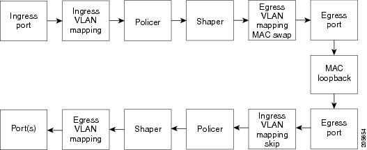
With terminal loopback, traffic that is looped back goes through the forwarding path a second time. If MAC swap is not configured. looped-back multicast or broadcast traffic is flooded on that VLAN. The packet then goes out the other ports twice, once from the ingress packet and once from the looped-back packet. See Figure 43-3.
You can configure only one terminal loopback per switch.
Figure 43-3 Terminal Loopback Packet Flow
By default, no loopbacks are configured.
Ethernet loopback has these characteristics:
•![]() You can configure Ethernet loopback only on physical ports, not on VLANs or port channels.
You can configure Ethernet loopback only on physical ports, not on VLANs or port channels.
•![]() You can configure one loopback per port and a maximum of two loopbacks per switch.
You can configure one loopback per port and a maximum of two loopbacks per switch.
•![]() You can configure only one terminal loopback per switch.
You can configure only one terminal loopback per switch.
•![]() The port ends the loopback after a port event, such as a shutdown or change from a switch port to a routed port.
The port ends the loopback after a port event, such as a shutdown or change from a switch port to a routed port.
•![]() When you configure VLAN loopback by entering the vlan vlan-list keywords, the VLANs are tunneled into an internal VLAN that is not forwarded to any ports. The tunnel ends at the egress, so it is transparent to the user.
When you configure VLAN loopback by entering the vlan vlan-list keywords, the VLANs are tunneled into an internal VLAN that is not forwarded to any ports. The tunnel ends at the egress, so it is transparent to the user.
•![]() VLAN loopback is not supported on nontrunk interfaces.
VLAN loopback is not supported on nontrunk interfaces.
•![]() Terminal loopback is not supported on routed interfaces.
Terminal loopback is not supported on routed interfaces.
•![]() You cannot configure SPAN and loopback on the switch at the same time. If you try to configure SPAN on any port while loopback is configured, you receive an error message.
You cannot configure SPAN and loopback on the switch at the same time. If you try to configure SPAN on any port while loopback is configured, you receive an error message.
•![]() If a port is a Flex Link port or belongs to an EtherChannel, it cannot be put into a loopback state. If loopback is active, you cannot add a port to a Flex Link or EtherChannel.
If a port is a Flex Link port or belongs to an EtherChannel, it cannot be put into a loopback state. If loopback is active, you cannot add a port to a Flex Link or EtherChannel.
•![]() Port loopback shares hardware resources with the VLAN mapping feature. If not enough TCAM resources are available because of VLAN-mapping configuration, when you attempt to configure loopback, you receive an error message, and the configuration is not allowed.
Port loopback shares hardware resources with the VLAN mapping feature. If not enough TCAM resources are available because of VLAN-mapping configuration, when you attempt to configure loopback, you receive an error message, and the configuration is not allowed.
Beginning in privileged EXEC mode, follow these steps to enable Ethernet facility loopback on an interface:
To stop an active loopback session on an interface or to stop all active loopback sessions, enter the ethernet loopback stop {interface-id | all} privileged EXEC command. To remove the Ethernet facility loopback configuration, enter the no ethernet loopback interface configuration command.
This example shows how to configure an Ethernet loopback to swap the MAC source and destination addresses. to never time out, and to start the loopback process. You must confirm the command before loopback starts.
Switch(config)# interface gigabitethernet 0/1
Switch(config-if)# ethernet loopback facility mac-address swap timeout none supported
Switch(config-if)# end
Switch# ethernet loopback start gigabitethernet 0/1
This is an intrusive loopback.
Therefore, while you test Ethernet connectivity,
you will be unable to pass traffic across that link.
Proceed with Local Loopback? [confirm]
This is the output from the show ethernet loopback privileged EXEC command for the previous
configuration:
Switch# show ethernet loopback
=====================================
Loopback Session 0 : Interface Gi0/1
Direction : facility
Type : port
Status : configured
MAC Mode : swap
Time out : none.
Beginning in privileged EXEC mode, follow these steps to configure Ethernet terminal loopback on an interface:
To disable Ethernet terminal configuration, enter the no ethernet loopback interface configuration command.
This example shows how to configure an Ethernet terminal loopback to test QoS on the interface, to swap the MAC source and destination addresses, to time out after 30 seconds, and to start the loopback process:
Switch(config)# interface gigabitethernet 0/1
Switch(config-if)# ethernet loopback terminal mac-address swap timeout 30 supported
Switch(config-if)# end
Switch# ethernet loopback start gigabitethernet 0/1
Understanding E-LMI
Ethernet Local Management Interface (E-LMI) is a protocol between the customer-edge (CE) device and the provider-edge (PE) device. It runs only on the PE-to-CE UNI link and notifies the CE device of connectivity status and configuration parameters of Ethernet services available on the CE port. E-LMI interoperates with an OAM protocol, such as CFM, that runs within the provider network to collect OAM status. CFM runs at the provider maintenance level (UPE to UPE with up MEPs at the UNI). E-LMI relies on the OAM Ethernet Infrastructure to interwork with CFM for end-to-end status of Ethernet virtual connections (EVCs) across CFM domains.
OAM manager, which streamlines interaction between any two OAM protocols, handles the interaction between CFM and E-LMI. This interaction is unidirectional, running only from OAM manager to E-LMI on the UPE side of the switch. Information is exchanged either as a result of a request from E-LMI or triggered by OAM when it received notification of a change from the OAM protocol. This type of information is relayed:
•![]() EVC name and availability status
EVC name and availability status
•![]() Remote UNI name and status
Remote UNI name and status
•![]() Remote UNI counts
Remote UNI counts
You can configure Ethernet virtual connections (EVCs), service VLANs, UNI ids (for each CE-to-PE link), and UNI count and attributes. You need to configure CFM to notify the OAM manager of any change to the number of active UNIs and or the remote UNI ID for a given S-VLAN domain.
You can configure the switch as either the customer-edge device or the provider-edge device.
E-LMI Interaction with OAM Manager
No interactions are required between E-LMI and OAM manager on the CE side. On the UPE side, OAM manager defines an abstraction layer that relays data collected from OAM protocols (in this case CFM) running within the metro network to the E-LMI switch. The information flow is unidirectional (from OAM manager to the E-LMI) but is triggered in one of two ways:
•![]() Synchronous data flow triggered by a request from the E-LMI
Synchronous data flow triggered by a request from the E-LMI
•![]() Asynchronous data flow triggered by OAM manager when it receives notification from CFM that the number of remote UNIs has changed
Asynchronous data flow triggered by OAM manager when it receives notification from CFM that the number of remote UNIs has changed
This data includes:
•![]() EVC name and availability status (active, not active, partially active, or not defined)
EVC name and availability status (active, not active, partially active, or not defined)
•![]() Remote UNI name and status (up, disconnected, administratively down, excessive FCS failures, or not reachable)
Remote UNI name and status (up, disconnected, administratively down, excessive FCS failures, or not reachable)
•![]() Remote UNI counts (the total number of expected UNIs and the actual number of active UNIs)
Remote UNI counts (the total number of expected UNIs and the actual number of active UNIs)
The asynchronous update is triggered only when the number of active UNIs has changed.
CFM Interaction with OAM Manager
When there is a change in the number of active UNIs or remote UNI ID for a given S-VLAN or domain, CFM asynchronously notifies the OAM manager. A change in the number of UNIs might (or might not) cause a change in EVC status. OAM manager calculates EVC status given the number of active UNIs and the total number of associated UNIs.
Note ![]() If crosscheck is disabled, no SNMP traps are sent when there is a change in the number of UNIs.
If crosscheck is disabled, no SNMP traps are sent when there is a change in the number of UNIs.
Configuring E-LMI
For E-LMI to work with CFM, you configure Ethernet virtual connections (EVCs), Ethernet service instances (EFPs), and E-LMI customer VLAN mapping. Most of the configuration occurs on the PE switch on the interfaces connected to the CE device. On the CE switch, you only need to enable E-LMI on the connecting interface. Note that you must configure some OAM parameters, for example, EVC definitions, on PE devices on both sides of a metro network.
This section includes this information:
•![]() E-LMI and OAM Manager Configuration Guidelines
E-LMI and OAM Manager Configuration Guidelines
•![]() Ethernet OAM Manager Configuration Example
Ethernet OAM Manager Configuration Example
Default E-LMI Configuration
Ethernet LMI is globally disabled by default. When enabled, the switch is in provider-edge (PE) mode by default.
When you globally enable E-LMI by entering the ethernet lmi global global configuration command, it is automatically enabled on all interfaces. You can also enable or disable E-LMI per interface to override the global configuration. The E-LMI command that is given last is the command that has precedence.
There are no EVCs, EFP service instances, or UNIs defined.
UNI bundling service is bundling with multiplexing.
E-LMI and OAM Manager Configuration Guidelines
OAM manager is an infrastructural element and requires two interworking OAM protocols, in this case CFM and E-LMI. For OAM to operate, the PE side of the connection must be running CFM and E-LMI.
•![]() E-LMI is not supported on routed ports, EtherChannel port channels or ports that belong to an EtherChannel, private VLAN ports, or IEEE 802.1Q tunnel ports.
E-LMI is not supported on routed ports, EtherChannel port channels or ports that belong to an EtherChannel, private VLAN ports, or IEEE 802.1Q tunnel ports.
•![]() You cannot configure E-LMI on VLAN interfaces.
You cannot configure E-LMI on VLAN interfaces.
•![]() When you enable E-LMI globally or on an interface, the switch is in PE mode by default, You must enter the ethernet lmi ce global configuration command to enable the switch or interface in customer-edge mode.
When you enable E-LMI globally or on an interface, the switch is in PE mode by default, You must enter the ethernet lmi ce global configuration command to enable the switch or interface in customer-edge mode.
•![]() When the switch is configured as a CE device, the service instance and ethernet uni interface commands are visible but not supported.
When the switch is configured as a CE device, the service instance and ethernet uni interface commands are visible but not supported.
Configuring the OAM Manager
Beginning in privileged EXEC mode, follow these steps to configure OAM manager on a PE switch:
Use the no forms of the commands to delete an EVC, EFP, or UNI ID, or to return to default configurations.
Note ![]() If you configure, change, or remove a UNI service type, EVC, EFP, or CE-VLAN configuration, all configurations are checked to make sure that the configurations match (UNI service type with EVC or EFP and CE-VLAN configuration). The configuration is rejected if the configurations do not match.
If you configure, change, or remove a UNI service type, EVC, EFP, or CE-VLAN configuration, all configurations are checked to make sure that the configurations match (UNI service type with EVC or EFP and CE-VLAN configuration). The configuration is rejected if the configurations do not match.
Enabling E-LMI
You can enable E-LMI globally or on an interface and you can configure the switch as a PE or a CE device. Beginning in privileged EXEC mode, follow these steps to enable for E-LMI on the switch or on an interface. Note that the order of the global and interface commands determines the configuration. The command that is entered last has precedence.
Use the no ethernet lmi global configuration command to globally disable E-LMI. Use the no form of the ethernet lmi interface configuration command with keywords to disable E-LMI on the interface or to return the timers to the default settings.
Use the show ethernet lmi commands to display information that was sent to the CE from the status request poll. Use the show ethernet service commands to show current status on the device.
Ethernet OAM Manager Configuration Example
This is a simple example of configuring CFM and E-LMI with OAM manager on a PE device and on a CE device. You can configure the switch as either the PE device or the CE device.
Provider-Edge Device Configuration
This example shows a sample configuration of OAM manager, CFM, and E-LMI on the PE device:
Switch# config t
Switch(config)# ethernet cfm domain Top level 7
Switch(config)# ethernet cfm domain Provider level 4
Switch(config-ether-cfm)# service customer_1 vlan 101
Switch(config-ether-cfm)# mep crosscheck mpid 404 vlan 101
Switch(config-ether-cfm)# exit
Switch(config)# ethernet cfm domain Operator_level 2
Switch(config-ether-cfm)# service operator_1 vlan 101
Switch(config-ether-cfm)# exit
Switch(config)# ethernet cfm enable
Switch(config)# ethernet evc test1
Switch(config-evc)# oam protocol cfm svlan 101 domain Provider
Switch(config-evc)# exit
Switch(config)# ethernet evc 101
Switch(config-evc)# uni count 3
Switch(config-evc)# oam protocol cfm svlan 101 domain Operator
Switch(config-evc)# exit
Switch(config)# ethernet lmi global
Switch(config)# interface gigabitethernet0/2
Switch(config-if)# ethernet cfm mip level 7
Switch(config-if)# ethernet cfm mep level 4 mpid 200 vlan 200
Switch(config-if)# service instance 101 ethernet test1
Switch(config-if-srv)# ethernet lmi ce-vlan map 101
Switch(config-if-srv)# exit
Switch(config-if)# exit
Switch(config)# ethernet cfm cc enable level 2-4 vlan 101
Switch(config)# exit
Customer-Edge Device Configuration
This example shows the commands necessary to configure E-LMI on the CE device. The switch can be configured as the CE device. The example enables E-LMI globally, but you can also enable it only on a specific interface. However, if you do not enter the ethernet lmi ce global configuration command, the interface will be in PE mode by default.
Switch# config t
Switch(config)# ethernet lmi global
Switch(config)# ethernet lmi ce
Switch(config)# exit
Note ![]() For E-LMI to work, any VLANs used on the PE device must also be created on the CE device. Create a VLAN by entering the vlan vlan-id global configuration command on the CE device, where the vlan-ids match those on the PE device and configure these VLANs as allowed VLANs by entering the switchport trunk allowed vlan vlan-ids interface configuration command. Allowed VLANs can receive and send traffic on the interface in tagged format when in trunking mode.
For E-LMI to work, any VLANs used on the PE device must also be created on the CE device. Create a VLAN by entering the vlan vlan-id global configuration command on the CE device, where the vlan-ids match those on the PE device and configure these VLANs as allowed VLANs by entering the switchport trunk allowed vlan vlan-ids interface configuration command. Allowed VLANs can receive and send traffic on the interface in tagged format when in trunking mode.
Displaying E-LMI and OAM Manager Information
You can use the privileged EXEC commands in Table 43-5 to display E-LMI or OAM manager information.
Ethernet CFM and Ethernet OAM Interaction
You can also configure the OAM Manager infrastructure for interaction between CFM and Ethernet OAM. When the Ethernet OAM Protocol is running on an interface that has CFM MEPs configured, Ethernet OAM informs CFM of the state of the interface. Interaction is unidirectional from the Ethernet OAM to the CFM Protocol, and the only information exchanged is the user network interface port status.
The Ethernet OAM Protocol notifies CFM when these conditions occur:
•![]() Error thresholds are crossed at the local interface.
Error thresholds are crossed at the local interface.
CFM responds to the notification by sending a port status of Local_Excessive_Errors in the Port StatusType Length Value (TLV).
•![]() Ethernet OAM receives an OAMPDU from the remote side showing that an error threshold is exceeded on the remote endpoint.
Ethernet OAM receives an OAMPDU from the remote side showing that an error threshold is exceeded on the remote endpoint.
CFM responds to the notification by sending a port status of Remote_Excessive_Errors in the Port Status TLV.
•![]() The local port is set into loopback mode.
The local port is set into loopback mode.
CFM responds by sending a port status of Test in the Port Status TLV.
•![]() The remote port is set into loopback mode.
The remote port is set into loopback mode.
CFM responds by sending a port status of Test in the Port Status TLV.
This section includes this information:
•![]() Configuring Ethernet OAM Interaction with CFM
Configuring Ethernet OAM Interaction with CFM
•![]() Ethernet OAM and CFM Configuration Example
Ethernet OAM and CFM Configuration Example
For more information about CFM and interaction with Ethernet OAM, see the Cisco IOS Carrier Ethernet Configuration Guide at this URL:
http://www.cisco.com/en/US/docs/ios/cether/configuration/guide/12_2sr/ce_12_2sr_book.html
Configuring Ethernet OAM Interaction with CFM
For Ethernet OAM to function with CFM, you must configure an Ethernet Virtual Circuit (EVC) and the OAM manager, and associate the EVC with CFM. You must use an up MEP for interaction with the OAM manager.
Note ![]() If you configure, change, or remove a UNI service type, EVC, Ethernet service instance, or CE-VLAN configuration, all configurations are verified to ensure that the UNI service types match the EVC configuration and that Ethernet service instances are matched with the CE-VLAN configuration. Configurations are rejected if the pairs do not match.
If you configure, change, or remove a UNI service type, EVC, Ethernet service instance, or CE-VLAN configuration, all configurations are verified to ensure that the UNI service types match the EVC configuration and that Ethernet service instances are matched with the CE-VLAN configuration. Configurations are rejected if the pairs do not match.
Configuring the OAM Manager
Beginning in privileged EXEC mode, follow these steps to configure the OAM manager on a PE device:
Enabling Ethernet OAM
Beginning in privileged EXEC mode, follow these steps to enable Ethernet OAM on an interface.
Ethernet OAM and CFM Configuration Example
These are example configurations of the interworking between Ethernet OAM and CFM in a sample service provider network with a provider-edge switch connected to a customer edge switch at each endpoint. You must configure CFM, E-LMI, and Ethernet OAM between the customer edge and the provider edge switch.
Customer-edge switch 1 (CE1) configuration:
Switch# config t
Switch(config)# interface gigabitethernet0/1
Switch(config-if)# port-type nni
Switch(config-if)# switchport trunk allowed vlan 10
Switch(config-if)# switchport mode trunk
Switch(config-if)# ethernet oam remote-loopback supported
Switch(config-if)# ethernet oam
Switch(config-if)# exit
Provider-edge switch 1 (PE1) configuration:
Switch# config t
Switch(config)# interface gigabitethernet0/5
Switch(config-if)# switchport trunk encapsulation dot1q
Switch(config-if)# switchport mode trunk
Switch(config-if)# ethernet cfm mip level 7
Switch(config-if)# ethernet cfm mep level 4 mpid 100 vlan 10
Switch(config-if)# ethernet uni id 2004-20
Switch(config-if)# ethernet oam remote-loopback supported
Switch(config-if)# ethernet oam
Switch(config-if)# service instance 10 ethernet BLUE
Switch(config-if-srv)# ethernet lmi ce-vlan map 10
Switch(config-if-srv)# exit
Provider-edge switch 2 (PE2) configuration:
Switch# config t
Switch(config)# interface gigabitethernet1/20
Switch(config-if)# switchport mode trunk
Switch(config-if)# ethernet cfm mip level 7
Switch(config-if)# ethernet cfm mep level 4 mpid 101 vlan 10
Switch(config-if)# ethernet uni id 2004-20
Switch(config-if)# ethernet oam remote-loopback supported
Switch(config-if)# ethernet oam
Switch(config-if)# service instance 10 ethernet BLUE
Switch(config-if-srv)# ethernet lmi ce-vlan map 10
Switch(config-if-srv)# exit
Customer-edge switch 2 (CE2) configuration:
Switch# config t
Switch(config)# interface gigabitethernet0/1
Switch(config-if)# port-type nni
Switch(config-if)# switchport trunk allowed vlan 10
Switch(config-if)# switchport mode trunk
Switch(config-if)# ethernet oam remote-loopback supported
Switch(config-if)# ethernet oam
Switch(config-if)# exit
These are examples of the output showing provider-edge switch port status of the configuration. Port status shows as UP at both switches.
Switch PE1:
Switch# show ethernet cfm maintenance points remote
MPID Level Mac Address Vlan PortState InGressPort Age(sec) Service ID
101 * 4 0015.633f.6900 10 UP Gi0/1 27 blue
Switch PE2:
Switch# show ethernet cfm maintenance points remote
MPID Level Mac Address Vlan PortState InGressPort Age(sec) Service ID
100 * 4 0012.00a3.3780 10 UP Gi0/1 8 blue
Total Remote MEPs: 1
This example shows the outputs when you start remote loopback on CE1 (or PE1). The port state on the remote PE switch shows as Test and the remote CE switch goes into error-disable mode.
Switch# ethernet oam remote-loopback start interface gigabitEthernet 0/1
This is a intrusive loopback.
Therefore, while you test Ethernet OAM MAC connectivity,
you will be unable to pass traffic across that link.
Proceed with Remote Loopback? [confirm]
Switch PE1:
Switch# show ethernet cfm maintenance points remote
MPID Level Mac Address Vlan PortState InGressPort Age(sec) Service ID
101 * 4 0015.633f.6900 10 UP Gi0/1 27 blue
Switch PE2:
Switch# show ethernet cfm maintenance points remote
MPID Level Mac Address Vlan PortState InGressPort Age(sec) Service ID
100 * 4 0012.00a3.3780 10 TEST Gi1/1/1 8 blue
Total Remote MEPs: 1
In addition, if you shut down the CE1 interface that connects to PE1, the remote PE2 port will show a PortState of Down.
 Feedback