The documentation set for this product strives to use bias-free language. For the purposes of this documentation set, bias-free is defined as language that does not imply discrimination based on age, disability, gender, racial identity, ethnic identity, sexual orientation, socioeconomic status, and intersectionality. Exceptions may be present in the documentation due to language that is hardcoded in the user interfaces of the product software, language used based on RFP documentation, or language that is used by a referenced third-party product. Learn more about how Cisco is using Inclusive Language.
Configuring VPLS: Routed Pseudowire IRB for IPv4 Unicast
The VPLS: Routed Pseudowire IRB for IPv4 Unicast feature allows a switch interface to route traffic instead of using a router.
Restrictions for Configuring VPLS: Routed Pseudowire IRB for IPv4 Unicast
This feature is not supported on the C9500-12Q, C9500-16X, C9500-24Q, C9500-40X models of the Cisco Catalyst 9500 Series Switches.
This feature is not supported on a domain configured with multicast routing protocols.
This feature is not supported for the IPv6 address family.
VPLS over GRE is not supported with integrated routing and bridging (IRB).
Information About VPLS: Routed Pseudowire IRB for IPv4 Unicast
The following sections provide information about VPLS: Routed Pseudowire IRB for IPv4 Unicast.
About VPLS: Routed Pseudowire IRB for IPv4 Unicast
The VPLS: Routed Pseudowire IRB for IPv4 Unicast feature allows a Virtual Private LAN Services (VPLS) multipoint provider
edge (PE) device interface to route the Layer 3 traffic along with switch the Layer 2 frames for pseudowire (PW) connections
between PE devices. Note that the ability to route frames between interfaces does not affect the termination of a PW into
the Layer 3 network (VPN or global) on the same device, or to tunnel Layer 3 frames over a Layer 2 tunnel (VPLS).
Centralized Integrated Routing and Bridging
In centralized Integrated Routing and Bridging (IRB), only one interface on a PE device is configured with IRB in the domain.
All the host devices that are connected to PE devices are configured with this IRB interface IP address as the gateway.
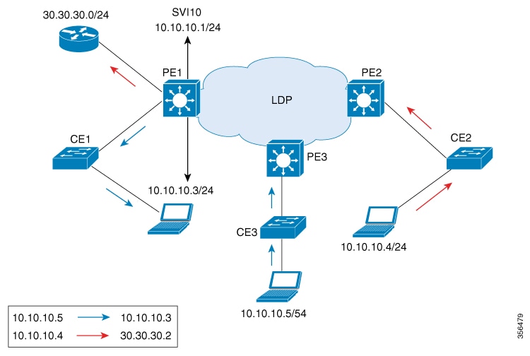
The following figure shows a domain configured with centralized IRB. The figure shows that IRB is configured on the PE device
(PE1) interface. All the hosts that are connected to the customer edge (CE) devices (CE1, CE2, and CE3), are configured with
the IRB interface IP address (10.10.10.1) as the gateway. In this scenario, only those packets that are destined for the Layer
3 router (30.30.30.0/24) undergo Layer 3 packet rewrite because these interfaces or routers are reachable from the PE1 device.
All the hosts communicate only in Layer 2 because they are part of the same bridge domain (10.10.10.x).
Figure 1. Centralized IRB
Distributed Integrated Routing and Bridging
In distributed IRB, all the interfaces across all the PE devices are configured with IRB in the domain. The routing protocols
enabled on the PE devices allow routes to be learnt between PE devices.
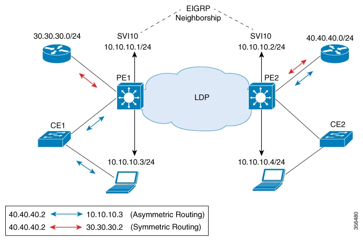
The following figure shows a domain that is configured with distributed IRB. Enhanced Interior Gateway Routing Protocol (EIGRP)
is configured on the interfaces of the PE devices (PE1 and PE2), which allows routers (30.30.30.0/24 and 40.40.40.0/24) to
exchange routes. Hosts connected to the CE devices are configured with the local IRB interface IP address as the gateway.
For example, host 10.10.10.3 is configured with IRB interface IP address 10.10.10.1 as the gateway, and host 10.10.10.4 is
configured with IRB interface IP address 10.10.10.2 as the gateway. In this scenario, if the incoming traffic is through a
switch virtual interface (SVI), the outgoing traffic can also be reached by SVI through the MPLS network because the relationship
is formed across IRB interfaces under the same bridge domain (10.10.10.x).
Figure 2. Distributed IRB
In the above diagram, where traffic is incoming on PE1 destined for a router interface reachable through PE2, routing takes
place on egress of the PE (that is, PE2) based on the gateway configuration. In such a scenario, the packet reaching PE2 always
has the source MAC as host MAC, and not the gateway MAC (which ages out after aging time). If the gateway MAC ages out, flooding
occurs in the reverse direction traffic. Therefore, we recommend that in case of asymmetric routing, you configure an ARP
timeout on the IRB interface that is lower than the MAC aging time so that flooding does not occur across PEs in the VPLS
domain.
In this scenario (where traffic is incoming from CE1), both ingress and egress interfaces point to the SVI in the forwarding
pipeline of PE1. Although this is expected, it generates ICMP redirect messages. Therefore, we recommend that you configure
no ip redirects command on the SVI in interface configuration mode so that ICMP redirect messages are not generated in case of distributed
IRB.
Features Supported with VPLS: Routed Pseudowire IRB for IPv4 Unicast
The following are the features that are supported on an interface that is configured with the VPLS: Routed Pseudowire IRB
for IPv4 Unicast feature:
IPv4 unicast routing protocols
Virtual routing and forwarding (VRF)
DHCP relay
Address Resolution Protocol (ARP) timeout
Blocking of Internet Control Message Protocol (ICMP) redirect messages
Configuring VPLS: Routed Pseudowire IRB for IPv4 Unicast
To configure VPLS: Routed Pseudowire IRB for IPv4 Unicast, perform this procedure.
Procedure
Command or Action
Purpose
Step 1
enable
Example:
Device> enable
Enables privileged EXEC mode.
Enter your password, if prompted.
Step 2
configure terminal
Example:
Device# configure terminal
Enters global configuration mode.
Step 3
interface vlanvlan-id
Example:
Device(config)# interface vlan 100
Configures a VLAN interface and enters interface configuration mode
Step 4
xconnect vfivfi-name
Example:
Device(config-if)# xconnect vfi VFI100
Specifies the Layer 2 VFI that you are binding to the VLAN port.
Step 5
ip addressip-addressmask
Example:
Device(config-if)# ip address 10.10.10.1 255.255.255.0
Assigns the IP address to the interface.
Example: Configuring Distributed IRB
The following example shows how to configure distributed IRB:
Device> enable
Device# configure terminal
Device(config)# template type pseudowire VPLS
Device(config-template)# encapsulation mpls
Device(config-template)# l2vpn vfi context VPLS
Device(config-template)# vpn id 10
Device(config-template)# member pseudowire1
Device(config-if)# end

Device(config)# interface pseudowire1
Device(config-if)# source template type pseudowire VPLS
Device(config-if)# encapsulation mpls
Device(config-if)# signaling protocol ldp
Device(config-if)# neighbor 10.10.10.10 10
Device(config-if)# end

Device(config)# interface Vlan10
Device(config-if)# ip address 10.10.10.1 255.255.255.0
Device(config-if)# no ip redirects
Device(config-if)# member vfi VPLS
Device(config-if)# end
Feature History for Configuring VPLS: Routed Pseudowire IRB for IPv4 Unicast
This table provides release and related information for the features explained in this module.
These features are available in all the releases subsequent to the one they were introduced in, unless noted otherwise.
Release
Feature
Feature Information
Cisco IOS XE Amsterdam 17.2.1
VPLS: Routed Pseudowire IRB for IPv4 Unicast
The VPLS: Routed Pseudowire IRB for IPv4 Unicast feature allows a switch interface to route traffic instead of using a router.
Use the Cisco Feature Navigator to find information about platform and software image support. To access Cisco Feature Navigator,
go to https://cfnng.cisco.com/
 Feedback