The documentation set for this product strives to use bias-free language. For the purposes of this documentation set, bias-free is defined as language that does not imply discrimination based on age, disability, gender, racial identity, ethnic identity, sexual orientation, socioeconomic status, and intersectionality. Exceptions may be present in the documentation due to language that is hardcoded in the user interfaces of the product software, language used based on RFP documentation, or language that is used by a referenced third-party product. Learn more about how Cisco is using Inclusive Language.
One-to-One VLAN mapping can be configured only on trunk ports and not on dynamic trunk.
One-to-One VLAN mapping should be identical on both ports.
S-VLAN should be created and present in the allowed VLAN list of the trunk port where One-to-One VLAN mapping is configured.
Restrictions for VLAN Mapping
If VLAN mapping is enabled on an EtherChannel, the configuration does not apply to all member ports of the EtherChannel bundle
but applies only to the EtherChannel interface.
If VLAN mapping is enabled on an EtherChannel and a conflicting mapping translation is enabled on a member port, the port
is removed from the EtherChannel.
If a port belonging to an EtherChannel is configured with a VLAN mapping and the EtherChannel is configured with a conflicting
VLAN mapping, the port is removed from the EtherChannel.
The member port of an EtherChannel is removed from the EtherChannel bundle if the mode of the port is changed to anything
other than ‘trunk’ mode.
Default native VLANs, user-configured native VLANs, and reserved VLANs cannot be used for VLAN mapping.
The S-VLAN used for VLAN mapping cannot be a part of any other Layer 3 configurations, EVPN or LISP.
PVLAN support is not available when VLAN mapping is configured.
Restrictions for One to One VLAN Mapping
When One-to-One VLAN mapping is configured, multiple C-VLANs cannot be mapped to the same S-VLAN
Merging of C-VLAN and S-VLAN spanning-tree topology is not supported in case of one-to-one vlan mapping.
About VLAN Mapping
In a typical deployment of VLAN mapping, you want service provider to provide a transparent
switching infrastructure that includes customers’ switches at the remote location as a
part of local site. This allows customers to use the same VLAN ID space and run Layer 2
control protocols seamlessly across the provider network. In such scenarios, we
recommend that service providers do not impose their VLAN IDs on their customers.
One way to establish translated VLAN IDs (S-VLANs) is to map customer VLANs to VLANs (called VLAN
ID translation) on trunk ports connected to a customer network. Packets entering the
port are mapped to service provider VLAN (S-VLAN) based on the port number and the
packet’s original customer VLAN-ID (C-VLAN).
Service providers’s internal assignments might conflict with a customer’s VLAN. To isolate
customer traffic, a service provider decides to map a specific VLAN into another one
while the traffic is in its cloud.
Deployment Example
In the figure, the service provider provides Layer 2
VPN service to two different customers, A and B. The service provider separates the
data and control traffic between the two customers and from the providers’ own
control traffic. The service provider network must also be transparent to the
customer edge devices.
All forwarding operations on Catalyst 9000 series switch are
performed using S-VLAN and not C-VLAN information because the VLAN ID is mapped to
the S-VLAN on ingress.
Note
When you configure features on a port for VLAN
mapping, you always use the S-VLAN rather than C-VLAN.
On an interface
configured for VLAN mapping, the specified C-VLAN packets are mapped to the
specified S-VLAN when they enter the port. Symmetrical mapping to the customer
C-VLAN occurs when packets exit the port.
The switch supports one-to-one VLAN mapping
on trunk ports.
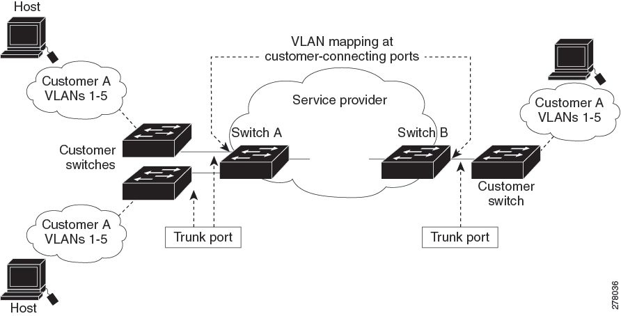
Figure 1. Mapping Customer VLANs to Service-Provider VLANs
Figure shows a topology where a customer uses
the same VLANs in multiple sites on different sides of a service-provider network.
The C-VLAN IDs is mapped to service-provider VLAN IDs for packet travel across the
service-provider backbone. The C-VLAN IDs are retrieved at the other side of the
service-provider backbone for use in the other customer site. Configure the same set
of VLAN mappings at a customer-connected port on each side of the service-provider
network.
The maximum number of VLAN mapping configurations supported
is 3000 system wide.The maximum number of VLAN mappings that can be configured on
each ASIC is 1000.
One-to-One VLAN Mapping
One-to-one VLAN mapping occurs at the ingress and egress of the port and maps the customer C-VLAN ID in the 802.1Q tag to
the service-provider S-VLAN ID. You can also specify that packets with all other Vlan IDs are forwarded.
Configuration Guidelines for VLAN Mapping
Note
By default, no VLAN mapping is configured.
Starting from Cisco IOS XE Amsterdam 17.2.1 the maximum number of VLAN mapping configurations supported is 3000 system wide. The maximum number of VLAN mappings that
can be configured on each ASIC is 1000.
Guidelines include the following:
If the VLAN mapping is enabled on an EtherChannel, the configuration does not apply to all member ports of the EtherChannel
bundle and applies only to the EtherChannel interface.
If the VLAN mapping is enabled on an EtherChannel and a conflicting mapping/translation is enabled on a member port, then
the port is removed from the EtherChannel.
If a port belonging to an EtherChannel is configured with a VLAN mapping and the EtherChannel is configured with a conflicting
VLAN mapping, then the port is removed from the EtherChannel.
The member port of an EtherChannel is removed from the EtherChannel bundle if the mode of the port is changed to anything
other than ‘trunk’ mode.
To process control traffic consistently, either enable Layer 2 protocol tunneling (recommended), as follows:
Default native VLANs, user-configured native VLANs, and reserved VLANs (range 1002-1005) cannot be used for VLAN mapping.
The S-VLAN used for VLAN mapping cannot be a part of any other Layer 3 configurations like EVPN or LISP.
PVLAN support is not available when VLAN mapping is configured.
Configuration Guidelines for One-to-One VLAN Mapping
One-to-One VLAN mapping can be configured only on trunk ports and not on dynamic trunk.
One-to-One VLAN mapping should be identical on both ports.
S-VLAN should be created and present in the allowed VLAN list of the trunk port where One-to-One VLAN mapping is configured.
When One-to-One VLAN mapping is configured, multiple C-VLANs cannot be mapped to the same S-VLAN.
Merging of C-VLAN and S-VLAN spanning-tree topology is not supported in case of one-to-one VLAN mapping.
How to Configure VLAN Mapping
The following sections provide information about configuring VLAN mapping:
One-to-One VLAN Mapping
Note
VLAN Mapping is supported only with the network-advantage license level.
To configure one-to-one VLAN mapping to map a customer VLAN ID to a service-provider VLAN ID, perform this task:
Procedure
Command or Action
Purpose
Step 1
enable
Example:
Device> enable
Enables privileged EXEC mode.
Enter your password if prompted.
Step 2
configure terminal
Example:
Device# configure terminal
Enters global configuration mode.
Step 3
interface interface-id
Example:
Device(config)# interface gigabitethernet1/0/1
Enters interface configuration mode for the interface that is connected to the service-provider network. You can enter a physical
interface or an EtherChannel port channel.
Step 4
switchport mode trunk
Example:
Device(config-if)# switchport mode trunk
Configures the interface as a trunk port.
Step 5
switchport vlan mappingvlan-id translated-id
Example:
Device(config-if)# switchport vlan mapping 2 102
Enters the VLAN IDs to be mapped:
vlan-id —the customer VLAN ID (C-VLAN) entering the switch from the customer network. The range is from 1 to 4094.
translated-id —the assigned service-provider VLAN ID (S-VLAN). The range is from 1 to 4094.
Step 6
exit
Example:
Device(config-if)# exit
Returns to global configuration mode.
Step 7
spanning-tree bpdufilter enable
Example:
Device(config)# spanning-tree bpdufilter enable
Inserts a BPDU filter for spanning tree.
Note
To process control traffic consistently, either enable Layer 2 protocol tunneling (recommended) or insert a BPDU filter for
spanning tree.
Step 8
end
Example:
Device(config)# end
Returns to privileged EXEC mode.
Step 9
show vlan mapping
Example:
Device# show vlan mapping
Verifies the configuration.
Step 10
copy running-config startup-config
Example:
Device# copy running-config startup-config
(Optional) Saves your entries in the configuration file.
Example
Use no switchport vlan mapping command to remove the VLAN mapping information. Entering no switchport vlan mapping all command deletes all mapping configurations.
This example shows how to map VLAN IDs 2 to 6 in the customer network to VLANs 101 to 105 in the service-provider network
(Figure 3-5). You configure the same VLAN mapping commands for a port in Switch A and Switch B; the traffic on all other VLAN
IDs is forwarded as normal traffic.
In the previous example, at the ingress of the service-provider network, VLAN IDs 2 to 6 in the customer network are mapped
to VLANs 101 to 105, in the service provider network. At the egress of the service provider network, VLANs 101 to 105 in the
service provider network are mapped to VLAN IDs 2 to 6, in the customer network.
Note
Packets with VLAN IDs other than the ones with configured VLAN Mapping are forwarded as normal traffic.
Use show vlan mapping command to view information about configured vlans.
Device> enable
Device# configure terminal
Device(config)# show vlan mapping
Total no of vlan mappings configured: 1
Interface Po5:
VLANs on wire                   Translated     VLAN Operation
------------------------------ --------------- --------------
20                                30            1-to-1
Feature History for VLAN Mapping
This table provides release and related information for features explained in this module.
These features are available on all releases subsequent to the one they were introduced in, unless noted otherwise.
Release
Feature
Feature Information
Cisco IOS XE Gibraltar 16.11.1
One-to-One VLAN mapping
One-to-One VLAN mapping allows to map customer VLANs to service-provider VLANs on trunk ports connected to a customer network.
Cisco IOS XE Amsterdam 17.2.1
Increase in VLAN translation scale
The number of VLAN mappings one can configure on the device has increased.
Use Cisco Feature Navigator to find information about platform and software image support. To access Cisco Feature Navigator,
go to http://www.cisco.com/go/cfn.


 Feedback