Information About VRF-lite
VRF-lite is a feature that enables a service provider to support two or more VPNs, where IP addresses can be overlapped among the VPNs. VRF-lite uses input interfaces to distinguish routes for different VPNs and forms virtual packet-forwarding tables by associating one or more Layer 3 interfaces with each VRF. Interfaces in a VRF can be either physical, such as Ethernet ports, or logical, such as VLAN SVIs, but a Layer 3 interface cannot belong to more than one VRF at any time.
 Note |
VRF-lite interfaces must be Layer 3 interfaces. |
VRF-lite includes these devices:
-
Customer edge (CE) devices provide customer access to the service provider network over a data link to one or more provider edge routers. The CE device advertises the site’s local routes to the provider edge router and learns the remote VPN routes from it. A Cisco Catalyst Switch can be a CE.
-
Provider edge (PE) routers exchange routing information with CE devices by using static routing or a routing protocol such as BGP, RIPv1, or RIPv2.
The PE is only required to maintain VPN routes for those VPNs to which it is directly attached, eliminating the need for the PE to maintain all of the service provider VPN routes. Each PE router maintains a VRF for each of its directly connected sites. Multiple interfaces on a PE router can be associated with a single VRF if all of these sites participate in the same VPN. Each VPN is mapped to a specified VRF. After learning local VPN routes from CEs, a PE router exchanges VPN routing information with other PE routers by using internal BGP (iBGP).
-
Provider routers (or core routers) are any routers in the service provider network that do not attach to CE devices.
With VRF-lite, multiple customers can share one CE. The shared CE maintains separate VRF tables for each customer and switches or routes packets for each customer based on its own routing table. VRF-lite allows a CE device to maintain separate VRF tables to extend the privacy and security of a VPN to the branch office.
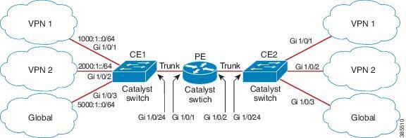
The following figure displays a configuration where each Cisco Catalyst switch acts as multiple virtual CEs. Because VRF-lite is a Layer 3 feature, each interface in a VRF must be a Layer 3 interface.
To configure VRF, create a VRF table and specify the Layer 3 interface associated with the VRF.
 Feedback