-
null
Bias-Free Language
The documentation set for this product strives to use bias-free language. For the purposes of this documentation set, bias-free is defined as language that does not imply discrimination based on age, disability, gender, racial identity, ethnic identity, sexual orientation, socioeconomic status, and intersectionality. Exceptions may be present in the documentation due to language that is hardcoded in the user interfaces of the product software, language used based on RFP documentation, or language that is used by a referenced third-party product. Learn more about how Cisco is using Inclusive Language.
- Updated:
- August 14, 2014
Chapter: Cisco IP Phone Support
Cisco IP Phone Support
- Prerequisites for Cisco IP Phone Support
- Restrictions for Cisco IP Phone Support
- Information About Cisco IP Phone Support
- Default Setting for Cisco IP Phone Support
- How to Configure Cisco IP Phone Support

Note ●![]() For complete syntax and usage information for the commands used in this chapter, see these publications:
For complete syntax and usage information for the commands used in this chapter, see these publications:
http://www.cisco.com/en/US/products/ps11846/prod_command_reference_list.html
- Cisco IOS Release 15.4SY supports only Ethernet interfaces. Cisco IOS Release 15.4SY does not support any WAN features or commands.
http://www.cisco.com/en/US/products/hw/switches/ps708/tsd_products_support_series_home.html
Participate in the Technical Documentation Ideas forum
Prerequisites for Cisco IP Phone Support
Restrictions for Cisco IP Phone Support
- The information in this publication may be helpful in configuring support for non-Cisco IP phones, but we recommend that you see the manufacturer’s documentation for those devices.
- You must enable the Cisco Discovery Protocol (CDP) on the port connected to the Cisco IP phone to send configuration information to the Cisco IP phone.
- You can configure a voice VLAN only on a Layer 2 LAN port.
- The following conditions indicate that the Cisco IP phone and a device attached to the Cisco IP phone are in the same VLAN and must be in the same IP subnet:
–![]() If they both use 802.1p or untagged frames
If they both use 802.1p or untagged frames
–![]() If the Cisco IP phone uses 802.1p frames and the device uses untagged frames
If the Cisco IP phone uses 802.1p frames and the device uses untagged frames
–![]() If the Cisco IP phone uses untagged frames and the device uses 802.1p frames
If the Cisco IP phone uses untagged frames and the device uses 802.1p frames
–![]() If the Cisco IP phone uses 802.1Q frames and the voice VLAN is the same as the access VLAN
If the Cisco IP phone uses 802.1Q frames and the voice VLAN is the same as the access VLAN
- The Cisco IP phone and a device attached to the Cisco IP phone cannot communicate if they are in the same VLAN and subnet but use different frame types, because traffic between devices in the same subnet is not routed (routing would eliminate the frame type difference).
- You cannot use Cisco IOS software commands to configure the frame type used by traffic sent from a device attached to the access port on the Cisco IP phone.
- If you enable port security on a port configured with a voice VLAN and if there is a PC connected to the Cisco IP phone, set the maximum allowed secure addresses on the port to at least 2.
- You cannot configure static secure MAC addresses in the voice VLAN.
- Ports configured with a voice VLAN can be secure ports (see Chapter 56, “Port Security”).
- In all configurations, the voice traffic carries a Layer 3 IP precedence value (the default is 5 for voice traffic and 3 for voice control traffic).
Information About Cisco IP Phone Support
- Cisco IP Phone Connections
- Cisco IP Phone Voice Traffic
- Cisco IP Phone Data Traffic
- Other Cisco IP Phone Features
Cisco IP Phone Connections
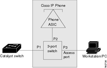
The Cisco IP phone contains an integrated 3-port 10/100 switch. The ports are dedicated connections to these devices:
- Port 1 connects to the switch.
- Port 2 is an internal 10/100 interface that carries the Cisco IP phone traffic.
- Port 3 connects to a PC or other device.
Figure 19-1 shows a Cisco IP phone connected between a switch and a PC.
Figure 19-1 Cisco IP Phone Connected to a Switch
Cisco IP Phone Voice Traffic
The Cisco IP phone transmits voice traffic with Layer 3 IP precedence and Layer 2 CoS values, which are both set to 5 by default. The sound quality of a Cisco IP phone call can deteriorate if the voice traffic is transmitted unevenly.
You can configure Layer 2 access ports on the switch to send Cisco Discovery Protocol (CDP) packets that configure an attached Cisco IP phone to transmit voice traffic to the switch in any of the following ways:
- In the voice VLAN, tagged with a Layer 2 CoS priority value
- In the access VLAN, tagged with a Layer 2 CoS priority value
- In the access VLAN, untagged (no Layer 2 CoS priority value)
Note![]() In all configurations, the voice traffic carries a Layer 3 IP precedence value (the default is 5 for voice traffic and 3 for voice control traffic).
In all configurations, the voice traffic carries a Layer 3 IP precedence value (the default is 5 for voice traffic and 3 for voice control traffic).
To provide more predictable voice traffic flow, you can configure QoS on the switch to trust the Layer 3 IP precedence or Layer 2 CoS value in the received traffic (see Chapter 32, “PFC QoS Overview”).
The trusted boundary device verification feature configures ports on the switch to apply configured QoS port trust commands only when the Cisco Discovery Protocol (CDP) verifies that the device attached to the port is a Cisco IP phone. See the “How to Configure Trusted Boundary with Cisco Device Verification” section.
You can configure a Layer 2 access port with an attached Cisco IP phone to use one VLAN for voice traffic and another VLAN for data traffic from a device attached to the Cisco IP phone.
Cisco IP Phone Data Traffic
Note ●![]() The ability to either trust or mark tagged data traffic from the device attached to the access port on the Cisco IP phone is called the “trusted boundary (extended trust for CDP devices)” feature.
The ability to either trust or mark tagged data traffic from the device attached to the access port on the Cisco IP phone is called the “trusted boundary (extended trust for CDP devices)” feature.
- You cannot use Cisco IOS software commands to configure the frame type used by data traffic sent from a device attached to the access port on the Cisco IP phone.
- Untagged data traffic from the device attached to the Cisco IP phone passes through the Cisco IP phone unchanged, regardless of the trust state of the access port on the Cisco IP phone.
To process tagged data traffic (traffic in 802.1Q or 802.1p frame types) from the device attached to the access port on the Cisco IP phone (see Figure 19-1), you can configure Layer 2 access ports on the switch to send CDP packets that instruct an attached Cisco IP phone to configure the access port on the Cisco IP phone to either of these two modes:
- Trusted mode—All traffic received through the access port on the Cisco IP phone passes through the Cisco IP phone unchanged.
- Untrusted mode—All traffic in 802.1Q or 802.1p frames received through the access port on the Cisco IP phone is marked with a configured Layer 2 CoS value. The default Layer 2 CoS value is 0. Untrusted mode is the default.
Most IP phones have no ability to notify the switch of link state changes on the IP phone’s access port. When a device attached to the access port is disconnected or disabled administratively, the switch is unaware of the change. Some Cisco IP phones can send a CDP message containing a host presence type length value (TLV) indicating the changed state of the access port link.
Other Cisco IP Phone Features
The switch provides support for authentication, authorization, and accounting (AAA) for Cisco IP phones, as described in Chapter54, “IEEE 802.1X Port-Based Authentication”
The switch also supports automatic tracking for Cisco Emergency Responder (Cisco ER) to help you manage emergency calls in your telephony network. For further information, see this URL:
http://www.cisco.com/en/US/products/sw/voicesw/ps842/tsd_products_support_series_home.html
Default Setting for Cisco IP Phone Support
How to Configure Cisco IP Phone Support
Configuring Voice Traffic Support
To configure the way in which the Cisco IP phone transmits voice traffic, perform this task:
When configuring the way in which the Cisco IP phone transmits voice traffic, note the following information:
- Enter a voice VLAN ID to send CDP packets that configure the Cisco IP phone to transmit voice traffic in 802.1Q frames, tagged with the voice VLAN ID and a Layer 2 CoS value (the default is 5). Valid VLAN IDs are from 1 to 4094. The switch puts the 802.1Q voice traffic into the voice VLAN.
- Enter the dot1p keyword to send CDP packets that configure the Cisco IP phone to transmit voice traffic in 802.1p frames, tagged with VLAN ID 0 and a Layer 2 CoS value (the default is 5 for voice traffic and 3 for voice control traffic). The switch puts the 802.1p voice traffic into the access VLAN.
- Enter the untagged keyword to send CDP packets that configure the Cisco IP phone to transmit untagged voice traffic. The switch puts the untagged voice traffic into the access VLAN.
- Enter the none keyword to allow the Cisco IP phone to use its own configuration and transmit untagged voice traffic. The switch puts the untagged voice traffic into the access VLAN.
- In all configurations, the voice traffic carries a Layer 3 IP precedence value (the default is 5).
- See “PFC QoS Overview,” for information about how to configure QoS.
- See the “Configuring a LAN Interface as a Layer 2 Access Port” section for information about how to configure the port as a Layer 2 access port and configure the access VLAN.
This example shows how to configure Gigabit Ethernet port 5/1 to send CDP packets that tell the Cisco IP phone to use VLAN 101 as the voice VLAN:
This example shows how to verify the configuration of Gigabit Ethernet port 5/1:
Configuring Data Traffic Support
Note![]() The trusted boundary feature is implemented with the platform qos trust extend command.
The trusted boundary feature is implemented with the platform qos trust extend command.
To configure the way in which an attached Cisco IP phone transmits data traffic, perform this task:
|
|
|
|
|---|---|---|
Router(config-if)# platform qos trust extend [ cos cos_value ] |
Configures the way in which an attached Cisco IP phone transmits data traffic. |
|
When configuring the way in which an attached Cisco IP phone transmits data traffic, note the following information:
- To send CDP packets that configure an attached Cisco IP phone to trust tagged traffic received from a device connected to the access port on the Cisco IP phone, do not enter the cos keyword and CoS value.
- To send CDP packets that configure an attached Cisco IP phone to mark tagged ingress traffic received from a device connected to the access port on the Cisco IP phone, enter the cos keyword and CoS value (valid values are 0 through 7).
- You cannot use Cisco IOS software commands to configure whether or not traffic sent from a device attached to the access port on the Cisco IP phone is tagged.
This example shows how to configure Gigabit Ethernet port 5/1 to send CDP packets that tell the Cisco IP phone to configure its access port as untrusted and to mark all tagged traffic received from a device connected to the access port on the Cisco IP phone with CoS 3:
This example shows how to configure Gigabit Ethernet port 5/1 to send CDP packets that tell the Cisco IP phone to configure its access port as trusted:
This example shows how to verify the configuration on Gigabit Ethernet port 5/1:
Note![]() In addition to CDP, you can also use LLDP MED on the port connecting to the Cisco IP Phone to detect and configure it.
In addition to CDP, you can also use LLDP MED on the port connecting to the Cisco IP Phone to detect and configure it.
http://www.cisco.com/en/US/products/hw/switches/ps708/tsd_products_support_series_home.html
Participate in the Technical Documentation Ideas forum
 Feedback