- Warnings
- Box Contents
- Tools and Equipment
- Installation Guidelines
- Verifying Switch Operation
- Mounting the Switch
Switch Installation
For initial switch setup, assigning the switch IP address, and powering on information, see the switch getting started guide on Cisco.com.
This chapter contains these topics:
- Warnings
- Box Contents
- Tools and Equipment
- Installation Guidelines
- Verifying Switch Operation
- Mounting the Switch
- Attaching the Adapter Bracket to the Switch (Optional)
- Installing the Power Cord Retainer (Optional)
- Installing the Cable Guard (Optional)
- Installing SFP and SFP+Modules
- 10/100/1000 PoE and PoE+Port Connections
- 10/100/1000 Port Connections
- Where to Go Next
Warnings
This section includes the warning statements relating to basic installation. Read this section before you start the installation procedure.
 Warning | Before working on equipment that is connected to power lines, remove jewelry (including rings, necklaces, and watches). Metal objects will heat up when connected to power and ground and can cause serious burns or weld the metal object to the terminals. Statement 43 |
Warning | Read the wall-mounting instructions carefully before beginning installation. Failure to use the correct hardware or to follow the correct procedures could result in a hazardous situation to people and damage to the system. Statement 378 |
Warning | Do not work on the system or connect or disconnect cables during periods of lightning activity. Statement 1001 |
Warning | Read the installation instructions before connecting the system to the power source. Statement 1004 |
Warning |
Warning | Class 1 laser product. Statement 1008 |
Warning | This equipment must be grounded. Never defeat the ground conductor or operate the equipment in the absence of a suitably installed ground conductor. Contact the appropriate electrical inspection authority or an electrician if you are uncertain that suitable grounding is available. Statement 1024 |
Warning | Ultimate disposal of this product should be handled according to all national laws and regulations. Statement 1040 |
Warning | For connections outside the building where the equipment is installed, the following ports must be connected through an approved network termination unit with integral circuit protection: 10/100/1000 Ethernet. Statement 1044 |
Warning | To prevent the system from overheating, do not operate it in an area that exceeds the maximum recommended ambient temperature of: <113°F (45°C). Statement 1047 |
 Note | The maximum operating temperature is 40°C for Catalyst 3560CX-12PD-S and C3560CX-8XPD-S switches and 45°C for all the other switch models. However, for WS-C3560CX-8XPD-S, the maximum operating temperature will be 35°C when installed inverted and under fully loaded conditions (maximum PoE and 10G SFP+ transceivers installed). |
Warning | This warning symbol means danger. You are in a situation that could cause bodily injury. Before you work on any equipment, be aware of the hazards involved with electrical circuitry and be familiar with standard practices for preventing accidents. Use the statement number provided at the end of each warning to locate its translation in the translated safety warnings that accompanied this device. Statement 1071 |
Warning | Voltages that present a shock hazard may exist on Power over Ethernet (PoE) circuits if interconnections are made using uninsulated exposed metal contacts, conductors, or terminals. Avoid using such interconnection methods, unless the exposed metal parts are located within a restricted access location and users and service people who are authorized within the restricted access location are made aware of the hazard. A restricted access area can be accessed only through the use of a special tool, lock and key or other means of security. Statement 1072 |
Warning | No user-serviceable parts inside. Do not open. Statement 1073 |
Warning | Installation of the equipment must comply with local and national electrical codes. Statement 1074 |
Warning | To prevent airflow restriction, allow clearance around the ventilation openings to be at least: 3 inches (7.6 cm). Statement 1076 |
Warning | Hot surface. Statement 1079 |
Box Contents
The switch getting started guide describes the box contents. If any item is missing or damaged, contact your Cisco representative or reseller for support.
Tools and Equipment
Obtain these necessary tools and equipment:
Installation Guidelines
When determining where to install the switch, verify that these guidelines are met:
-
Clearance to front panels is such that the LEDs can be easily read.
-
Power cord reaches from the power outlet to the connector on the switch.
-
Cabling is away from sources of electrical noise, such as radios, power lines, and fluorescent lighting fixtures.
-
Temperature around the unit does not exceed 113°F (45°C). If the switch is installed in a closed or multirack assembly, the temperature around it might be greater than normal room temperature.
Note
The Catalyst 3560CX-12PD-S and C3560CX-8XPD-S switches have a maximum operating temperature of 40°C. All the other switches have a maximum operating temperature of 45°C. However, for WS-C3560CX-8XPD-S, the maximum operating temperature will be 35°C when installed inverted and under fully loaded conditions (maximum PoE and 10G SFP+ transceivers installed).
-
Humidity around the switch does not exceed 95 percent.
-
Altitude at the installation site is not greater than 10,000 feet.
-
Airflow around the switch and through the vents must be unrestricted. To avoid any flow blockage, we strongly recommend these guidelines:
-
Allow at least 3 in. (7.6 cm) of clearance from the left and right sides, and the front and rear of the switch.
-
If you are installing the switch upright, allow at least 1.75 in. (4 cm) of clearance from the top cover.
-
If you are installing the switch inverted, under a table, allow at least 3 in. (7.6 cm) of clearance from the top cover.
-
If you are installing the switch in a rack, allow at least 1RU of empty rack space above each switch.
Note
For Catalyst 3560CX-12PD-S and C3560CX-8XPD-S switches operating at the maximum specified temperature and fully loaded conditions (with transceivers installed and maximum PoE), when installed inverted, there should be unrestricted airflow all around the switch (and not just limited to the minimum 3 in. requirement). When installed upright, at least 3 in. of clearance from the top cover is required. When installed in a rack, at least 2RU of empty rack space above each switch is required.
-
-
When placing the switch on a flat horizontal surface, we strongly recommend that you attach the rubber feet to the switch.
-
For 10/100/1000 fixed ports, cable lengths from the switch to connected devices can be up to 328 feet (100 meters).
-
For cable requirements for SFP module connections, see the “SFP Module Cables” section. Each port must match the wave-length specifications on the other end of the cable, and the cable must not exceed the minimum cable length.
Verifying Switch Operation
Before you install the switch in a rack, on a wall, or on a table or shelf, power on the switch and verify that it passes POST.
To power on the switch, do one of the following, depending on your switch model:
-
Connect a 10/100/1000 uplink port to a PoE or PoE+ switch.
-
Plug the auxiliary power adapter cord into the switch AUX power connector and into an AC power outlet.
Note
You can use both the uplink port and the auxiliary power adapter. The switch shares power from all the available power sources. The total available power to the switch is the sum of power available from all the power sources minus the power that is lost.
-
Plug one end of the AC power cord into the switch AC power connector, and plug the other end into an AC power outlet.
Note | If you have a Catalyst WS-C3560CX-8PT-S switch that is connected to a Power Source Equipment (PSE) PoE or PoE+ port with ether-channel configuration, do not power on the switch by connecting only one 10/100/1000 uplink port to the PSE. Doing so will cause the PSE to detect a port channel misconfiguration when the switch tries to boot in low power mode, and hence the port will go into error disabled mode. For Catalyst WS-C3560CX-8PT-S switches, you must connect both uplink ports to the PSE. Alternatively, use the auxiliary power supply. For more details on Low Power Bootup, see the PoE and PoE Pass-Through Ports on Catalyst WS-C3560CX-8PT-S section in the Configuring PoE chapter of the switch's Software Configuration Guide on Cisco.com. |
As the switch powers on, it begins the POST, a series of tests that runs automatically to ensure that the switch functions properly. LEDs can blink during the test. POST lasts approximately 1 minute. When the switch begins POST, the SYST, STAT, and SPEED LEDs turn green. The SYST LED blinks green, and the other LEDs remain solid green.
When the switch completes POST successfully, the SYST LED remains green. The other LEDs turn off and then reflect the switch operating status. If a switch fails POST, the SYST LED turns amber.
POST failures are usually fatal. Call Cisco technical support representative if your switch fails POST.
After a successful POST, unplug the power cord from the switch and install the switch in a rack, on a wall, on a table, or on a shelf.
Mounting the Switch
Mounting on a Desk or Shelf Without Mounting Screws
On a Desk, Shelf, or Wall (with Mounting Screws)
Desk- or Shelf-Mounting
| Step 1 | Use the screw template to align the mounting screw holes and also as a guide to make sure that you install the screws into the desk or shelf with proper clearance. | ||
| Step 2 | Position the
screw template on top of the desk or shelf so that the edge that is marked as
CABLE SIDE ENTRY faces the front of the desk or shelf. This ensures that the
power cord faces the rear of the desk or shelf after the switch is installed.
| ||
| Step 3 | Peel the adhesive strip off the bottom of the screw template, and attach it to the top of the desk or shelf. | ||
| Step 4 | Use a 0.144-inch (3.7 mm) or a #27 drill bit to drill a 1/2-inch (12.7 mm) hole in the two screw template slots. | ||
| Step 5 | Insert two
screws in the slots on the screw template, and tighten them until they touch
the top of the screw template.
 | ||
| Step 6 | Remove the screw template from the desk or shelf. | ||
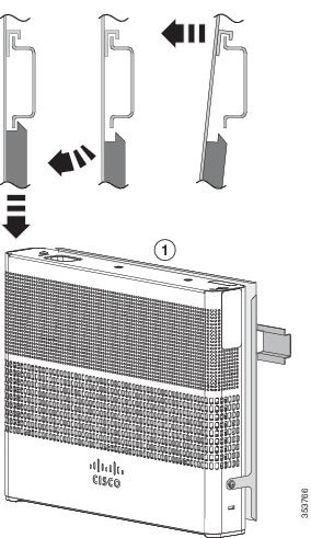
| Step 7 | Place the
switch onto the mounting screws, and slide it forward until it locks in place.
|
Under a Desk- or Shelf-Mounting
| Step 1 | Use the screw template to align the mounting screw holes and also as a guide to make sure that you install the screws under the desk or shelf with proper clearance. | ||
| Step 2 | Position the
screw template on top of the desk or shelf so that the edge that is marked as
CABLE SIDE ENTRY faces the front of the desk or shelf. This ensures that the
power cord faces the rear of the desk or shelf after the switch is installed.
| ||
| Step 3 | Peel the adhesive strip off the bottom of the screw template, and attach it to the top of the desk or shelf. | ||
| Step 4 | Use a 0.144-inch (3.7 mm) or a #27 drill bit to drill a 1/2-inch (12.7 mm) hole in the two screw template slots. | ||
| Step 5 | Insert two
screws in the slots on the screw template, and tighten them until they touch
the top of the screw template.
 | ||
| Step 6 | Remove the screw template from underneath the desk or shelf. | ||
| Step 7 | Place the
switch upside down onto the mounting screws, and slide it forward until it
locks in place.
 |
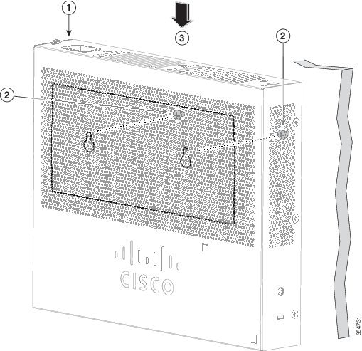
Wall-Mounting
Warning | Read the wall-mounting instructions carefully before beginning installation. Failure to use the correct hardware or to follow the correct procedures could result in a hazardous situation to people and damage to the system. Statement 378 |
 Caution | Do not wall-mount the switch with its front panel facing up. Following safety regulations, wall-mount the switch with its front panel facing down or to the side to prevent airflow restriction and to provide easier access to the cables |
| Step 1 | Locate the screw template. The template is used to align the mounting screw holes. | ||
| Step 2 | Position the
screw template so that the edge that is marked as CABLE SIDE ENTRY faces toward
the floor.
| ||
| Step 3 | Peel the adhesive strip off the bottom of the screw template. | ||
| Step 4 | Attach the screw template to the wall. | ||
| Step 5 | Use a 0.144-inch (3.7 mm) or a #27 drill bit to drill a 1/2-inch (12.7 mm) hole in the two screw template slots. | ||
| Step 6 | Insert two
screws in the slots on the screw template, and tighten them until they touch
the top of the screw template.
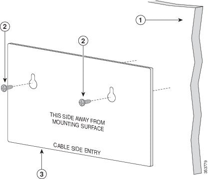 | ||
| Step 7 | Remove the screw template from the wall. | ||
| Step 8 | Place the
switch onto the mounting screws, and slide it down until it locks in place.
 |
With a Mounting Tray
The mounting kit (part number CMPCT-MGNT-TRAY=) is optional. You can order it when you order your switch, or you can order it later from your Cisco representative.
You can use the mounting tray by itself with mounting screws, or with a magnet.
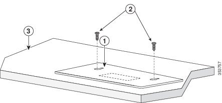
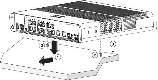
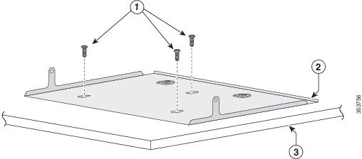
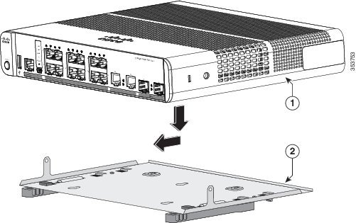
Mounting Tray with Screws
Caution | Do not wall-mount the switch with its front panel facing up. Following safety regulations, wall-mount the switch with its front panel facing down or to the side, to allow sufficient airflow and to provide easier access to the cables. |
This example shows you how to mount the switch on a desk or shelf. You can use a similar procedure to mount the switch under a desk or on a wall.
| Step 1 | Place the mounting tray on the desk. | ||
| Step 2 | Use a 0.144-in. (3.7 mm) or a #27 drill bit to drill three 1/2-in. (12.7 mm) holes in the desk. | ||
| Step 3 | Insert the
three number-8 Phillips pan-head screws in the slots on the mounting tray, and
tighten them.
 | ||
| Step 4 | Place the
switch onto the mounting screws, and slide the switch until it locks into
place.
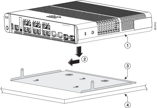 | ||
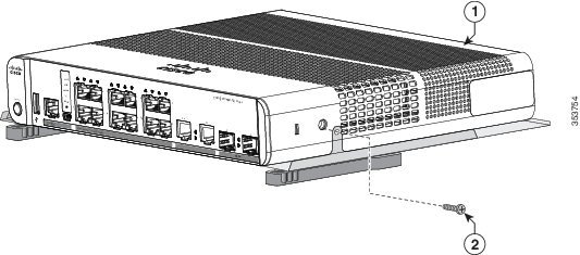
| Step 5 | Use the two
number-10 Phillips pan-head screws to secure the switch to the mounting tray.
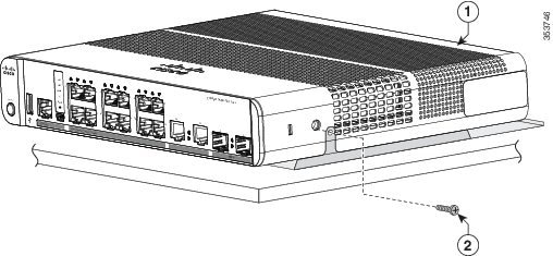
|
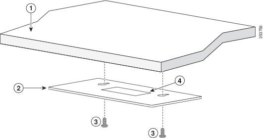
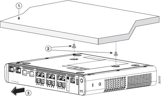
Mounting Tray with a Magnet
You can use a magnet with the mounting tray to mount the switch on a metal surface.
Caution | Do not use the magnet without a mounting tray |
This example shows you how to mount the switch on a metal wall. You can use a similar procedure to mount the switch on, or under, a metal desk.
| Step 1 | Place the
switch on the mounting tray.
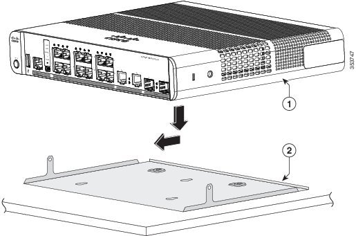 | ||||||
| Step 2 | Use the two
number-10 Phillips pan-head screws to secure the mounting tray to the switch.
| ||||||
| Step 3 | Place one side
of the magnet against the bottom of the mounting tray. Mount the magnet and
switch on a metal wall.
|
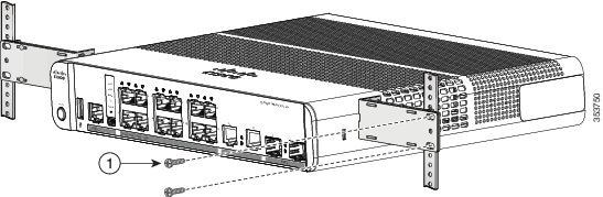
In a Rack
Warning |
Attach a bracket to one side of the switch. Follow the same steps to attach the second bracket to the opposite side. The following figures show how to attach the 19-inch rack-mounting bracket and the 23-inch rack-mounting bracket.

Insert the switch into the rack and align the bracket in the rack. Use either the number-12 or number-10 Phillips machine screws to secure the switch in the rack.
Warning | To prevent airflow restriction, allow clearance around the ventilation openings to be at least: 3 in. (7.6 cm) Statement 1076 |
On a DIN Rail
The DIN-mount kit (part number CMPCT-DIN-MNT=) is optional. You can order it when you order your switch, or you can order it later from your Cisco representative.
To install the switch on a DIN rail, follow the instructions described in these sections:
- Attaching the DIN-Mount Tray to the Switch
- Mounting the Switch on a DIN Rail
- Removing the Switch from a DIN Rail
Attaching the DIN-Mount Tray to the Switch
| Step 1 | Place the
switch on the DIN rail mount.
| ||||
| Step 2 | Use the two
number-10 Phillips pan-head screws to secure the DIN rail mount to the switch.
|
Mounting the Switch on a DIN Rail
Caution | Do not install the switch with its front panel facing up. Following safety regulations, install the switch with its front panel facing down, to allow sufficient airflow and to provide easier access to the cables. |
Warning | To prevent airflow restriction, allow clearance around the ventilation openings to be at least: 3 in. (7.6 cm) Statement 1076 |
| Step 1 | Position the
switch directly in front of the DIN rail, making sure that the top of the DIN
rail mount clip hooks over the top of the DIN rail.
 |
| Step 2 | Rotate the switch down toward the DIN rail until the release tabs on the DIN rail mount clicks. |
| Step 3 | Lift lightly on the bottom of the switch to ensure that it is firmly locked in place. |
Removing the Switch from a DIN Rail
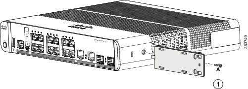
Attaching the Adapter Bracket to the Switch (Optional)
| Step 1 | Ensure that you
have attached the switch to a mounting tray or a DIN rail mount.
| ||
| Step 2 | Place the adapter into the power adapter bracket. | ||
| Step 3 | Insert the 3
tabs of the power adapter bracket into the corresponding 3 slots on the rear
side of the mounting tray or DIN rail mount.
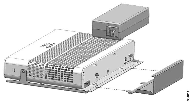 | ||
| Step 4 | Insert the
screws in the holes on the mounting tray or DIN rail mount, and tighten them.
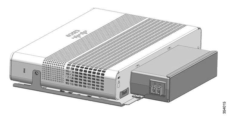 |
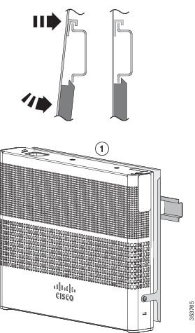
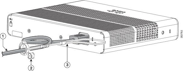
Installing the Power Cord Retainer (Optional)
Note | This section applies to switches with an AC power connector. |
The power cord retainer part number (PWR-CLP=) is optional. You can order it when you order your switch, or you can order it later from your Cisco representative.
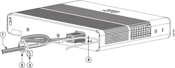
| Step 1 | Choose the sleeve size of the power cord retainer based on the thickness of the cord. The smaller sleeve can be snapped off and used for thin cords. | ||||||||
| Step 2 | Slide the
retainer around the AC power cord, and pass it around the loop on the switch.
| ||||||||
| Step 3 | Slide the
retainer through the first latch.
| ||||||||
| Step 4 | Slide the
retainer through the other latches to lock it.
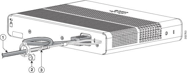
| ||||||||
| Step 5 | (Optional) Use
the small sleeve for thin power cords. Use the small sleeve to provide greater
stability for thin cords. Detach the sleeve, and slide it over the power cord.
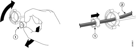
| ||||||||
| Step 6 | Secure the AC
power cord by pressing on the retainer.
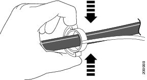 |
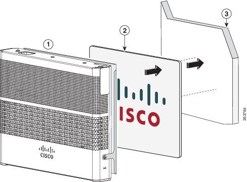
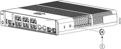
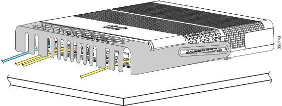
Installing the Cable Guard (Optional)
The cable guard prevents tampering with the cables after the cables are installed. The cable guard (CMPCT-CBLE-GRD=) is not included with the switch, but you can order it from your Cisco representative.
Note | You can use the cable guard when the switch is mounted on a desk, under a desk, or on a wall. |
The cable guard is shipped with these items:
| Step 1 | (Optional)
Attach the supplied washers before you install the cable guard.
| ||||||||
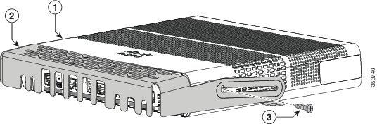
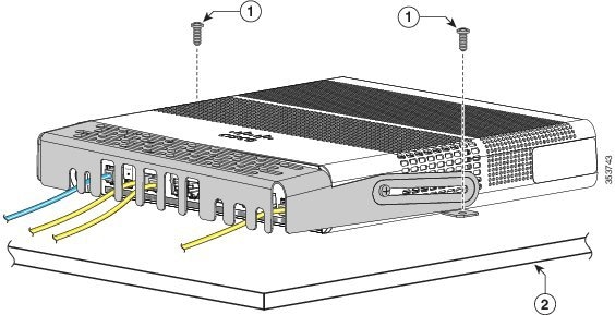
| Step 2 | Use the
supplied number-10 pan-head screws to attach the cable guard to the switch.
| ||||||||
| Step 3 | Loosen the
number-10 Phillips pan-head screws, slide the cable guide out, and pivot it
upwards so that you can install the cables.
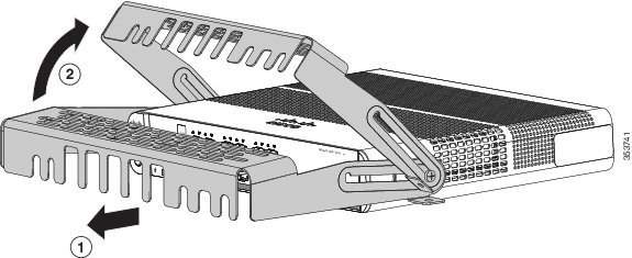
| ||||||||
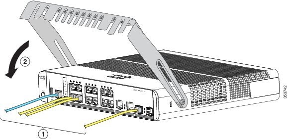
| Step 4 | Attach the
cables to the switch.
| ||||||||
| Step 5 | Guide the
connected cables through the slots in the front of the cable guard. Slide the
cable guide in as shown in the following figure. Tighten the screws
 | ||||||||
| Step 6 | (Optional) To
attach the cable guard to the desk or wall, use a 0.144-inch (3.7 mm) or a #27
drill bit to drill 1/2-inch (12.7 mm) holes at each of the two mounting
locations. Insert the supplied 0.5 in. (12.7 mm) number-8 Phillips wood screws
and tighten them.
|
Installing SFP and SFP+Modules
Some switch models support SFP modules, SFP+ modules, or both. The SFP slots support only the SFP modules. The SFP+ slots support both SFP and SFP+ modules.
See the switch release notes on Cisco.com for the list of supported SFP modules. Use only Cisco SFP modules on the switch. Each Cisco module has an internal serial EEPROM that is encoded with security information. This encoding provides a way for Cisco to identify and validate that the module meets the requirements for the switch.
For information about installing, removing, cabling, and troubleshooting SFP modules, see the module documentation that shipped with your device.
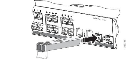
Installing an SFP or SFP+Module
When installing SFP or SFP+ modules, observe these guidelines:
-
Do not remove the dust plugs from the modules or the rubber caps from the fiber-optic cable until you are ready to connect the cable. The plugs and caps protect the module ports and cables from contamination and ambient light.
-
To prevent ESD damage, follow your normal board and component handling procedures when connecting cables to the switch and other devices.
Caution
Removing and installing an SFP or SFP+ module can shorten its useful life. Do not remove and insert any module more often than is absolutely necessary.
Warning
Class 1 laser product. Statement 1008
| Step 1 | Attach an ESD-preventive wrist strap to your wrist and to a bare metal surface. |
| Step 2 | Find the send (TX) and
receive (RX) markings on the module top.
On some SFP or SFP+ modules, the send and receive (TX and RX) markings might be replaced by arrows that show the direction of the connection. |
| Step 3 | If the module has a bale-clasp latch, move it to the open, unlocked position. |
| Step 4 | Align the module in front of the slot opening, and push until you feel the connector snap into place. |
| Step 5 | If the module has a bale-clasp latch, close it. |
| Step 6 | For fiber-optic SFP or SFP+ modules, remove the dust plugs and save. |
| Step 7 | Connect the SFP cables.
 |
Removing an SFP or SFP+Module
| Step 1 | Attach an ESD-preventive wrist strap to your wrist and to a bare metal surface. |
| Step 2 | Disconnect the cable from the SFP module. For reattachment, note which cable connector plug is send (TX) and which is receive (RX). |
| Step 3 | Insert a dust plug into the optical ports of the SFP or SFP+ module to keep the optical interfaces clean. |
| Step 4 | If the module has a bale-clasp latch, pull the bale out and down to eject the module. If the latch is obstructed and you cannot use your finger, use a small, flat-blade screwdriver or other long, narrow instrument to open the latch. |
| Step 5 | Grasp the SFP or SFP+ module, and carefully remove it from the module slot. |
| Step 6 | Place the module in an antistatic bag or other protective environment. |
10/100/1000 PoE and PoE+Port Connections
The ports provide PoE support for devices compliant with IEEE 802.3af and 802.3at (PoE+), and also provide Cisco prestandard PoE support for Cisco IP Phones and Cisco Aironet Access Points.
On a per-port basis, you can control whether or not a port automatically provides power when an IP phone or an access point is connected.
To access an advanced PoE planning tool, use the Cisco Power Calculator available on Cisco.com at this URL: http://tools.cisco.com/cpc/launch.jsp
You can use this application to calculate the power supply requirements for a specific PoE configuration. The results show output current, output power, and system heat dissipation.
Warning | Voltages that present a shock hazard may exist on Power over Ethernet (PoE) circuits if interconnections are made using uninsulated exposed metal contacts, conductors, or terminals. Avoid using such interconnection methods, unless the exposed metal parts are located within a restricted access location and users and service people who are authorized within the restricted access location are made aware of the hazard. A restricted access area can be accessed only through the use of a special tool, lock and key or other means of security. Statement 1072 |
Caution | Category 5e and Category 6 cables can store high levels of static electricity. Always ground the cables to a suitable and safe earth ground before connecting them to the switch or other devices. |
Caution | Noncompliant cabling or powered devices can cause a PoE port fault. Use only standard-compliant cabling to connect Cisco prestandard IP Phones and wireless access points, IEEE 802.3af, or 802.3at (PoE+)-compliant devices. You must remove any cable or device that causes a PoE fault. |
1. Connect one end of the cable to the switch PoE port.
2. Connect the other end of the cable to an RJ-45 connector on the other device. The port LED turns on when both devices have established link.
DETAILED STEPS
| Step 1 | Connect one end of the cable to the switch PoE port. | ||
| Step 2 | Connect the other end of the
cable to an RJ-45 connector on the other device. The port LED turns on when
both devices have established link.
The port LED is amber while STP discovers the topology and searches for loops. This process takes about 30 seconds, and then the port LED turns green. If the LED is off, the other device might not be turned on, there might be a cable problem, or there might be a problem with the adapter in the other device. | ||
| Step 3 | Reconfigure and reboot the connected device if needed. | ||
| Step 4 | Repeat Steps 1 through 3 to
connect each device.
|
10/100/1000 Port Connections
The switch 10/100/1000 port configuration changes to operate at the speed of the attached device. If the attached ports do not support autonegotiation, you can manually set the speed and duplex parameters. Connecting devices that do not autonegotiate or that have the speed and duplex parameters manually set can reduce performance or result in no linkage.
To maximize performance, choose one of these methods for configuring the Ethernet ports:
Auto-MDIX Connections
The autonegotiation and the auto-MDIX features are enabled by default on the switch.
With autonegotiation, the switch port configurations change to operate at the speed of the attached device. If the attached device does not support autonegotiation, you can manually set the switch interface speed and duplex parameters.
With auto-MDIX, the switch detects the required cable type for copper Ethernet connections and configures the interface accordingly.
Where to Go Next
If the default configuration is satisfactory, the switch does not need further configuration. You can use any of these management options to change the default configuration:
- Start the Network Assistant application, which is described in the getting started guide. Through this GUI, you can configure and monitor a switch cluster or an individual switch.
- Use the CLI to configure the switch as a member of a cluster or as an individual switch from the console.
- Use the Cisco Prime Infrastructure application.
 Feedback