Cisco Nexus 7000 Series NX-OS Intelligent Traffic Director Configuration Guide
Bias-Free Language
The documentation set for this product strives to use bias-free language. For the purposes of this documentation set, bias-free is defined as language that does not imply discrimination based on age, disability, gender, racial identity, ethnic identity, sexual orientation, socioeconomic status, and intersectionality. Exceptions may be present in the documentation due to language that is hardcoded in the user interfaces of the product software, language used based on RFP documentation, or language that is used by a referenced third-party product. Learn more about how Cisco is using Inclusive Language.
- Updated:
- March 29, 2016
Chapter: Deployment and Best Practices
Deployment and Best
Practices
Design and Deployment Considerations
This section describes the design and deployment considerations in ITD.
Number of ITD Services
An ITD Service configuration defines the ITD traffic distribution for a particular direction of the traffic flow. If both directions of a flow are required to be redirected, two ITD services should be configured: one for the forward, and another for the return traffic flow. Because an ASA has different Inside and Outside interface IP addresses, two different device-groups should be configured that point to the corresponding Inside and Outside IP addresses.
Additional ASA VLANs
The ITD Forward and Return services are attached to the inside and outside VLAN SVIs on the Nexus switch. To enable a security application, such as a firewall, requires that all traffic is examined, no traffic filtering is configured on the services. As a result, any traffic that hits the SVI is redirected to the corresponding ASA interfaces.
If ASA interfaces are configured on the same VLANs as that of the switch, the traffic going back to switch from the firewall is redirected back to the ASA due to the presence of an ITD service on other VLAN on the switch. So, a pair of separate VLANs should be used to prevent traffic looping between the firewalls and the Nexus Switches.
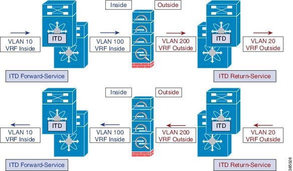
The above example shows the VLANs 10 and 20 being the inside and outside interfaces towards the source and destination on the network, and VLANs 100 and 200 being used towards the ASAs to enable loop-free traffic.
Link-Failure Scenario
When one of the interfaces of the ASA, either inside or outside, fails, then traffic coming into the other side of that ASA is blackholed as the egress interface for traffic is down. The ITD Peer-VDC Node-State Sync feature resolves this issue by removing the remote side of the ASA from ITD by synchronizing the node-states across the VDCs.
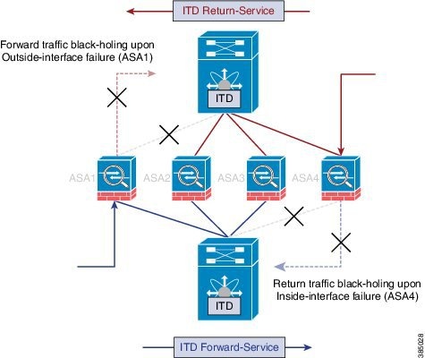
The ITD Peer-VDC Node-State-Sync feature currently supported only in the Dual VDC non-vPC single switch topology. ASA-Clustering also solves this problem as the clustering ensures the ASA is fully brought down in case of such failures. The Firewall-on-a-stick implementation, either single link or vPC, does not experience this issue as the inside and outside interfaces on the ASA belong to the same physical or virtual interface.
Deployment of ITD ASA
- Configuration Example: Firewall on a Stick
- Configuration Example: Firewall in Dual VDC Sandwich Mode with vPC
- Configuration Example: Firewall in Layer 3 Clustering
- Configuration Example: ITD for WCCP-Type Scenarios
Configuration Example: Firewall on a Stick
In a firewall on a stick deployment, the VPC port-channel (or single port) trunks are used to connect the ASAs to the switches, refer the figure below. In this configuration, the inside and outside interfaces are dot1q sub-interfaces(VLAN 100, 200) and the switches have two VLANs/SVIs each in the inside and outside contexts without physical-port separation between them.
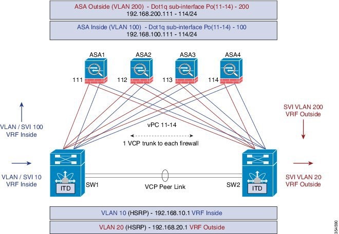
The following is the sample configuration snippets of the Nexus 7000. The example shows partial configurations from a switch (sw1). The configuration must be to be extended appropriately towards all the ASAs similarly. Other features are assumed to be configured already.
interface vlan 10
description Inside_Vlan_to_Network
vrf member INSIDE
ip address 192.168.10.10/24
hsrp 10
ip 192.168.10.1

interface vlan 20
description Outside_Vlan_to_Network
vrf member OUTSIDE
ip address 192.168.20.10/24
hsrp 20
ip 192.168.20.1

interface vlan100
description Inside_Vlan_to_ASA
vrf member INSIDE
ip address 192.168.100.10/24
hsrp 100
ip 192.168.100.1

interface vlan200
description Outside_Vlan_to_ASA
vrf member OUTSIDE
ip address 192.168.200.10/24
hsrp 200
ip 192.168.200.1

...............................

interface Port-Channel111
 description VPC_TO_ASA1
 switchport mode trunk
 switchport trunk allowed vlan 100,200
 vpc 11
 no shutdown

interface Ethernet 4/25
 description Link_To_ITD_ASA-1
 switchport
 switchport mode trunk
 switchport trunk allowed vlan 100,200
 channel-group 11 mode active
 no shutdown

interface Port-Channel41
 description Downstream_vPC_to_Network
 switchport mode trunk
 switchport trunk allowed vlan 10,20
 vpc 41
 no shutdown

interface Port-Channel 5/1-4
 description Downstream_vPC_member
 switchport
 switchport mode trunk
 switchport trunk allowed vlan 10,20
 channel-group 41
 no shutdown

........

itd device-group FW_INSIDE
 # config Firewall Inside interfaces as nodes

   node ip 192.168.100.111
   node ip 192.168.100.112
   node ip 192.168.100.113
   node ip 192.168.100.114
probe icmp frequency 5 timeout 5 retry-count 1

itd device-group FW_OUTSIDE
 # config Firewall Outside interfaces as nodes

   node ip 192.168.100.111
   node ip 192.168.100.112
   node ip 192.168.100.113
   node ip 192.168.100.114
probe icmp frequency 5 timeout 5 retry-count 1

.........

itd INSIDE
 vrf INSIDE
  #applies ITD service to VRF "INSIDE"
  #FW inside interfaces attached to service.
ingress interface Vlan 10
#applies ITD route-map to VLAN 1101 interface
failaction node reassign
# To use the next available Active FW if a FW goes offline
load-balance method src ip buckets 16
#distributes traffic into 16 buckets
#load balances traffic based on Source-IP.
  OUTSIDE service uses Dst-IP
no shutdown

itd OUTSIDE
 vrf OUTSIDE
  #applies ITD service to VRF "OUTSIDE"
device-group FW_OUTSIDE
ingress interface Vlan 10
failaction node reassign
load-balance method dst ip buckets 16
#distributes traffic into 16 buckets
#load balances traffic based on Destination-IP.
#OUTSIDE service uses Dst-IP
no shutdown
The following is the configuration snippets of ASA. The ASA side of the configuration is show below from one ASA(ASA-1). Similar configuration must be extended to all the other ASAs.
interface Port-Channel11
 nameif aggregate
 security-level 100
 no ip address
!
interface Port-Channel11.100
 description INSIDE
 vlan 100
 nameif inside
 security-level 100
 ip address 192.168.100.111 255.255.255.0
!
interface Port-Channel11.200
 description OUTSIDE
 vlan 200
 nameif outside
 security-level 100
 ip address 192.168.200.111 255.255.255.0
!
same-security-traffic permit inter-interface

.........

interface TenGigabitEthernet0/6
 description CONNECTED_TO_SWITCH_A_VPC
 channel-group 11 mode active
 no nameif
 no security-level

interface TenGigabitEthernet0/7
 description CONNECTED_TO_SWITCH_B_VPC
 channel-group 11 mode active
 no nameif
 no security-level
!
-
VLANs 10, 20,100, and, 200 and their SVI mapping to appropriate VRFs.
-
ITD device-group configuration for ASA - inside and outside.
-
ITD – load-balancing configuration for achieving flow-symmetry.
-
In a vPC scenario, as long as one member of the vPC is up, there will be no change to the ITD. The ITD redirection on the switch with the failed vPC leg traverses the peer-switch through the peer-link as in a typical vPC case.
-
This topology and deployment method does not blackhole traffic when a physical link failure occurs, as the inside and outside interfaces are tied to the same physical or virtual interface on the ASA (dot1q sub-interfaces).
-
To support Routing Protocol neighborship over vPC (Cisco NX-OS 7.2(0)D1(1) and later releases), the command layer3 peer-router should be configured within the vPC domain.
-
The VRFs are needed because layer 3 interfaces are used to connect to both inside and outside firewall interfaces. VRFs are put in place to prevent traffic from being (inter-vlan) routed around the firewall in certain cases.
-
Traffic is directed towards ASAs via PBR, thus routes are not needed.
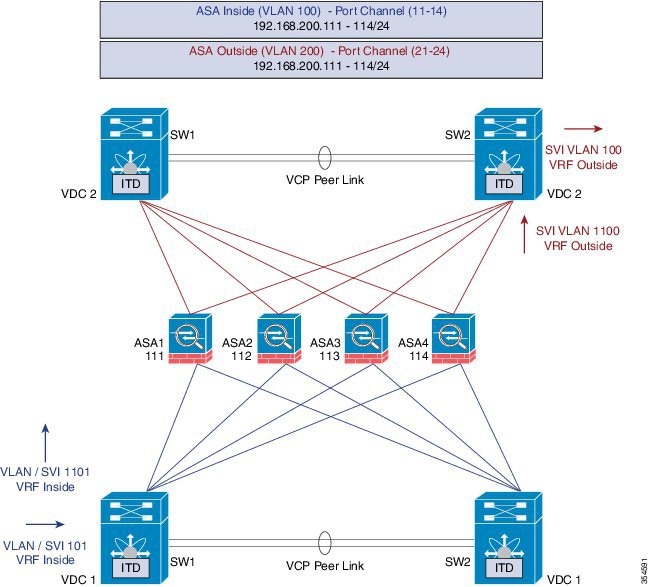
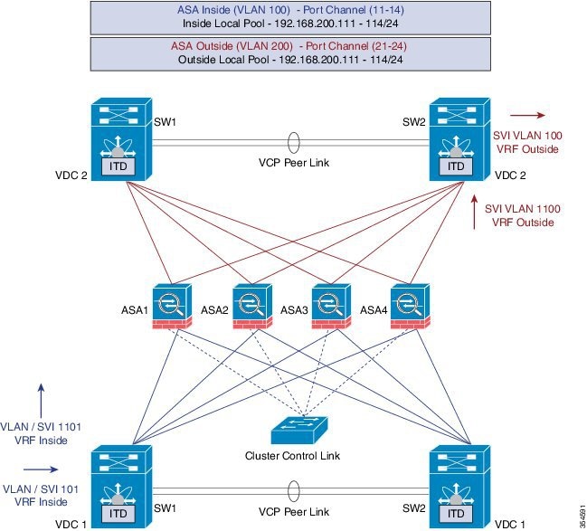
Configuration Example: Firewall in Dual VDC Sandwich Mode with vPC
Sandwich mode with vPC the Inside and Outside ASA interfaces are each assigned to separate port-channel bundles. This topology illustrated in the figure below, with Nexus 7000 currently does not support the node-state synchronization feature. As a consequence of vPC, a single link failure does not impede traffic-flow and ITD will continue to forward throught the peer-switch's link towards the ASA, similar to the other scenarios with vPC.
Configuration steps in Nexus 7000
The main differences in this topology from the single switch topology are that there are vPC port-channels instead of single links between the Nexus switch and the ASA. Secondly, as in the previous case, the inside and outside interfaces on the switches are configured in different VDCs.
The following is the configuration from the VDC1:
interface vlan 10
description INSIDE_VLAN
ip address 192.168.10.10/24

interface vlan 100
description FW_INSIDE_VLAN
ip address 192.168.100.10/24

interface Port-Channel11
 description To_ASA-1-INSIDE
 switchport mode access
 switchport access vlan 100
 vpc 11

interface Ethernet4/1
 description To_ASA-1-INSIDE
 switchport mode access
 switchport access vlan 100
 channel-group 11 mode active
The following is the configuration from the VDC2:
interface vlan 20
description OUTSIDE_VLAN
ip address 192.168.20.10/24

interface vlan 200
description FW_OUTSIDE_VLAN
ip address 192.168.200.10/24

interface Port-Channel21
 description To_ASA-1-OUTSIDE
 switchport mode access
 switchport access vlan 200
 vpc 11

interface Ethernet4/25
 description To_ASA-1-OUTSIDE
 switchport mode access
 switchport access vlan 200
 channel-group 21 mode active
Configuration steps in ASA
The following is the configuration snippet from the ASA.
interface Port-Channel11
 description INSIDE
 vlan 100
 nameif inside
 security-level 100
 ip address 192.168.100.111 255.255.255.0

interface Port-Channel21
 description OUTSIDE
 vlan 100
 nameif outside
 security-level 100
 ip address 192.168.200.111 255.255.255.0

same-security-traffic permit inter-interface

interface TenGigabitEthernet0/6
 description CONNECTED_TO_SWITCH0-A-VPC
 channel-group 11 mode active
 no nameif
 no security-level

interface TenGigabitEthernet0/7
 description CONNECTED_TO_SWITCH-B-VPC
 channel-group 11 mode active
 no nameif
 no security-level

interface TenGigabitEthernet0/8
 description CONNECTED_TO_SWITCH-A-VPC
 channel-group 21 mode active
 no nameif
 no security-level

interface TenGigabitEthernet0/9
 description CONNECTED_TO_SWITCH-B-VPC
 channel-group 21 mode active
 no nameif
 no security-level
-
ITD – Load-balancing configuration for achieving flow-symmetry.
-
In a vPC scenario, as long as one member of the vPC is up, there will be no change to ITD. The ITD redirection on the switch with the failed vPC leg would now traverse the peer-switch through the peer-link as in a typical vPC case.
-
In this topology or deployment method blackholing of traffic can occur, if one of the port channels on the ASA, or single physical link in non-VPC case, fails.
-
To support Routing Protocol neighborship over vPC, in Cisco NX-OS 7.2(0)D1(1) and later releases, the command layer3 peer-router should be configured within the vPC domain.
-
Traffic is directed towards ASAs via PBR, so routes are not needed.
Configuration Example: Firewall in Layer 3 Clustering
An ASA cluster consists of multiple ASAs acting as a single unit. Grouping multiple ASAs together as a single logical device provides the convenience of a single device, in terms of management and integration into a network, while achieving the increased throughput and redundancy of multiple devices. Refer the figure below.
ACL Clustering
The following table is a summary comparison of the impact on CCL that occurs with ECMP versus the impact that occurs with ITD, when the ASA device status changes:
|
ASA Status |
ITD |
ECMP |
|---|---|---|
|
Steady state |
Minimal traffic on CCL. Expected traffic types. Exactly same load-distribution irrespective of the type of line card and switch. |
Minimal traffic on CCL if same line card type and switch model is used everywhere. If differing hardware is used, a higher level of asymmetry may occur causing traffic on the CCL network. Each hardware has different hash function. Two switches (eg in vPC) might send same flow to different ASA, causing CCL traffic. |
|
Single ASA failure |
No additional traffic on CCL. ITD offers IP stickiness and Resilient Hashing. |
All flows are rehashed and additional traffic redirection occurs on CCL. This may effect a degree of traffic to all ASAs in the cluster. |
|
Single ASA recovery |
Traffic redirection can occur on the CCL between two ASAs in the cluster, the recovered ASA that receives a bucket and the ASA that serviced that bucket prior. |
Additional traffic redirection can occur on CCL. This may effect a degree of traffic to all ASAs in the cluster. |
|
ASA addition |
Minimal additional traffic on CCL. |
All flows are rehashed and additional traffic redirection occurs on CCL. This may effect a degree of traffic to all ASAs in the cluster. |
ITD can load balance to individual mode Layer 3 (L3) ASA clusters. ITD is complimentary to clustering in that ITD provides predictability of knowing which flows handled by each firewall. ITD buckets determine this instead of relying on OSPF ECMP and Port-Channel hashing algorithms.
With L3 clusters, the flow owner can be pre-determined based on the bucket allocation. Without ITD and L3 clustering the initial choice of Owner is typically unpredictable however with ITD this can be predetermined.
ASA clustering also uses the implementation of a backup flow owner. For every flow traversing any particular firewall in the cluster, another firewall stores the state of that flow and the ASA that owns the flow. If the real active flow owner fails, ITD failaction reassign causes all flows in the bucket from the failed owner ASA to shift to the next active node listed in the device-group. If the new firewall to receive this traffic is not the appropriate backup owner for the flows it receives, it should receive the flow state information from the backup owner and process traffic seamlessly, for more information, refer the Cisco ASA Series CLI Configuration Guide, 9.0.
A potential drawback to using ASA clustering with ITD is that backup flows and other cluster table operations consume memory and CPU resources that non-clustered firewalls do not. Therefore, there may be a firewall performance improvement with using non-clustered firewalls. However, the assurance of knowing that existing connections should not timeout if an ASA cluster member were to fail may be of greater value to customers.
Configuration steps in Nexus 7000
Introduction of Clustering does not change the ITD configuration. The ITD Nexus configuration depends on the type of topology, and in this example it is the same as the Firewall with Dual VDC Sandwich with vPC topology.
The ITD configuration remains similar to the previous method except that the node-state synchronization are removed.
Configuration steps in ASA
The ASA clustering is configured as an L3 cluster, similar to the PBR Deployment Scenario, described in the following document. The detailed information can be found at the link below regarding ASA Cluster configuration. The following is a sample configuration from the ASA is shown below for the Firewall in Layer 3 Clustering topology, for more information, refer: Cisco ASA Series CLI Configuration Guide, 9.0
cluster group ASA-CLUSTER-L3
local-unit ASA1
cluster-interface port-channel1 ip 192.168.250.100 255.255.255.0
priority 1
health-check holdtime 1.5
clacp system-mac auto system-priority 1
enable

mac-address pool MAC-INSIDE aaaa.0101.0001 - aaa.0101.0008
mac-address pool MAC-OUTSIDE aaaa.0100.0001 - aaa.0100.0008
ip local pool IP-OUTSIDE 192.168.200.111-192.168.200.114
ip local pool IP-INSIDE 192.168.100.111-192.168.100.114

interface Port-Channel11
 description INSIDE
 lacp max-bundle 8
 mac-address cluster-pool MAC-INSIDE
 nameif inside
 security-level 100
 ip address 192.168.100.11 255.255.255.0 cluster-pool IP-INSIDE

interface Port-Channel21
 description OUTSIDE
 lacp max-bundle 8
 mac-address cluster-pool MAC-OUTSIDE
 nameif outside
 security-level 100
 ip address 192.168.200.11 255.255.255.0 cluster-pool IP-OUTSIDE

interface Port-Channel31
 description Clustering Interface
 lacp max-bundle 8


interface TenGigabitEthernet0/6
 channel-group 11 mode active
 no nameif
 no security-level
 no ip address

interface TenGigabitEthernet0/7
 channel-group 11 mode active
 no nameif
 no security-level
 no ip address

interface TenGigabitEthernet0/8
 channel-group 21 mode active
 no nameif
 no security-level
 no ip address

interface TenGigabitEthernet0/9
channel-group 21 mode active
 no nameif
 no security-level
 no ip address

interface TenGigabitEthernet1/0
channel-group 31 mode active
 no nameif
 no security-level
 no ip address

interface TenGigabitEthernet1/1
channel-group 31 mode active
 no nameif
 no security-level
 no ip address
As seen in the above configuration, the Port-Channels 11 and 21 are used for either the inside or outside interfaces as in previous cases. However, there is an additional Port-channel 31 now for the Clustering Interface. Individual interfaces are normal routed interfaces, each with their own IP address taken from a pool of IP addresses. The main cluster IP address is a fixed address for the cluster that always belongs to the current master unit. Similarly, a mac-address pool is also configured and used under the corresponding Port-channel, either inside or outside.
Configuration Example: ITD for WCCP-Type Scenarios
Design with Web-Proxy
In Web-Proxy deployment with ITD, the Nexus switch takes responsibility of matching the internet-bound Web traffic and Load-balancing it towards the proxy-servers.
The proxy-servers would work in an autonomous mode(independent of WCCP and as Active-Active) and handle the traffic that gets redirected to them. The node health-probing done through ITD serves the purpose of tracking the state of the nodes, and removing or adding them back appropriately based on their availability. Standby servers can also be configured at a group-level or at node-level for redundancy.
Number of Services
As illustrated in the packet-flow slides, ITD redirection is normally only required in the forward direction in the client facing VLAN. Subsequently, the packets get routed/forwarded without any ITD redirection or distribution. ITD with such Web-Proxy deployments would only need one ITD service, and this is configured for the forward direction.However, must there be a requirement for reverse traffic redirection, traffic selection would need to be based on the Source L4 Ports. Flow symmetry also needs to be maintained by reversing the LB parameter.
Probes for Proxy-Health-Monitoring
With ITD for Web-proxy deployments, ITD probes are used to check availability of the Web-Proxy server. This is important as traffic that is sent towards a failed proxy-server will be blackholed. The probes that are available at present, in the respective latest releases per platform, are:
Roadmap: Probes parity across platform is targetted for future releases. Additional HTTP probe is being investigated.
 Note | These are not confirmed but roadmap items. |
Traffic Selection Requirements
The following are the currently supported methods for traffic-filtering or traffic-selection for ITD:
-
Virtual IP (Supported on Nexus 5000, Nexus 6000, Nexus 7000 and Nexus 9000):
IP + Subnet mask combination used for traffic selection(filtering) for the destination-field only.
-
Exclude ACL:
ACL used to specify which traffic should bypass ITD.
Traffic not permitted by this ACL will go through ITD.
Exclude ACL can filter based on both Source and Destination fields. Exclude ACL precedes VIP.
Exclude ACL only supports permit ACE entries. deny ACE’s are not supported on the exclude ACL.
-
Port-number based filtering
For selecting traffic based on L4 Ports, for ex. "Port 80 needs ITD service" we can do it today with the following: -
Matching Destination Ports: VIP – 0.0.0.0 0.0.0.0 tcp 80 (any source or destination IP, destination port 80 matched)
-
Matching Source Ports: Exclude ACL with “permit tcp any neq 80 any” (Any port not 80 will bypass ITD, port 80 is redirected).
-
Matching multiple Port-numbers: Multiple VIP lines in ITD can be configued, one for each port.
-
-
Include ACL: Roadmap Item - Cisco Nexus 7000 Release 7.3(0)D1(1), Cisco Nexus 9000 Release 7.0(3)I3(1)
For selecting traffic based on L4 Ports, for ex. "Port 80 needs ITD service" we can do it today with the following: -
Include ACL used to permit the traffic that should be ITD-serviced. Both SRCand DST fields can be matched.
-
Only Permit lines allowed. Either VIP or Include ACL can be used at a time, but not both.
-
Load-balancing parameter will determine the max. length of the match possible in the include ACL. For example, with source-based LB and 8 buckets, maximum mask of source IP address that can be matched is /29. With destination LB with 8 buckets, maximum mask of destination IP that can be matched is /29.
Note
The include ACL feature is a roadmap item and is not available on any current release. The information provided here is tentative only, and is subject to change.
-
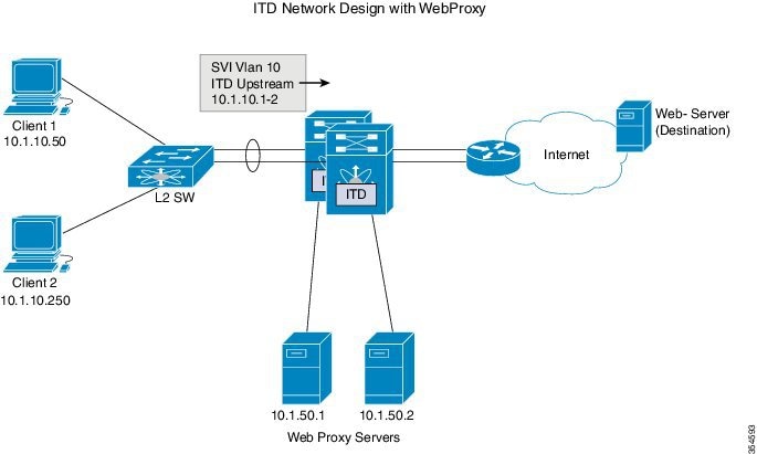
As indicated in the above figure, the destination port 80/443 (ingressVLAN10) to Internet is distributed to Web-Proxy servers 10.1.50.1/10.1.50.2.
Traffic on VLAN 10 destined to private networks (10.0.0.0/8, 192.168.0.0/16 and 172.16.0.0/20) is not sent to the proxy server.
 itd device-group Web_Proxy_Servers  	           <<<< Configure ITD Device-group Web_Proxy_Servers and point to server IP addresses.
  probe icmp
  node ip 10.1.50.1
  node ip 10.1.50.2

ip access-list itd_exclude_ACL                	  <<<< Configure Exclude ACL to exclude all traffic destined to Private IP addresses.
  10 permit ip any 10.0.0.0 255.0.0.0
  20 permit ip any 192.168.0.0 255.255.0.0
  30 permit ip any 172.16.0.0 255.255.240.0

Itd Web_proxy_SERVICE
  device-group Web_Proxy_Servers   	             <<<< Apply Exclude ACL.
  exclude access-list itd_exclude_ACL
  virtual ip 0.0.0.0 0.0.0.0 tcp 80   		         <<<< Any Traffic TO DESTINATION Port-80 redirect to group  Web_Proxy_Servers
  virtual ip 0.0.0.0 0.0.0.0 tcp 443  		         <<<< Any Traffic TO DESTINATION Port-443 redirect to group Web_Proxy_Servers
  ingress interface Vlan 10
  failaction node reassign
  load-balance method src ip
  no shutdown
When there is a need for return traffic redirection, the following additional configuration is required.
Note | Only port filtering is possible using the Layer 4 range’ operator. Exclude ACL supports only permit entries. |
ip access-list itd_exclude_return														<<<< Configure Exclude ACL (Return) to exclude all but port 80 & 443
  10 permit tcp any range 0 79 any
  20 permit tcp any range 81 442 any
  10 permit tcp any range 444 65535 any

itd Web_proxy_SERVICE																										<<<< Configure Return ITD service for return traffic:
  device-group Web_Proxy_Servers
  exclude access-list itd_exclude_return							<<<< Apply Exclude ACL for Return ITD service.
  ingress interface Vlan 20			 																<<<<  Internet-facing ingress interface on the Nexus Switch.
  failaction node reassign
  load-balance method dst ip																			<<<<  Flow symmetry between forward/retrun flow achieved by flipping LB parameter.
  no shutdown
As seen in the above configuration, the Port-Channels 11 and 21 are used for either the inside or outside interfaces as in previous cases. However, there is an additional Port-channel 31 now for the clustering interface. Individual interfaces are normal routed interfaces, each with their own IP address taken from a pool of IP addresses. The main cluster IP address is a fixed address for the cluster that always belongs to the current master unit. Similarly, a mac-address pool is also configured and used under the corresponding Port-channel, either inside or outside.
 Feedback