Overview
The Cisco Nexus 9336PQ ACI Spine Switch (N9K-C9336PQ) is a 2-rack-unit (RU) switch for the Cisco Application-Centric Infrastructure (ACI). This switch includes the following components:
-
36 fixed 40-Gigabit Quad Small Form-factor Pluggable (QSFP+) ports
-
Console and out-of-band-management ports (one each)
-
Fan modules (two)
-
Port-side intake version with burgundy coloring (N9K-C9300-FAN3)
-
Port-side exhaust version with blue coloring (N9K-C9300-FAN3-B)
-
-
Power supplies (two—one required for operations and an optional one for redundancy)
-
1200-W AC power supply with port-side intake airflow (burgundy coloring) (N9K-PAC-1200W)
-
1200-W AC power supply with port-side exhaust airflow (blue coloring) (N9K-PAC-1200W-B)
-
1200-W HVAC/HVDC power supply with dual-direction airflow (white coloring) (N9K-PUV-1200W)
-
930-W DC power supply with port-side intake airflow (green coloring) (UCSC-PSU-930WDC)
-
930-W DC power supply with port-side exhaust airflow (gray coloring) (UCS-PSU-6332-DC)
-
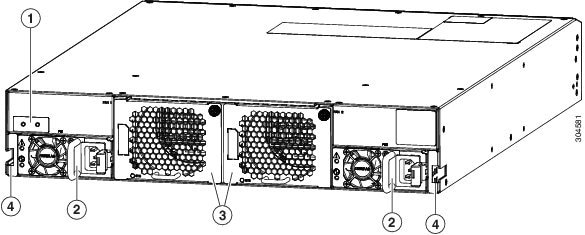
The following figure shows the hardware features seen on the power supply side of the chassis.
|
1 |
Grounding Pad |
3 |
Fan modules (2) |
|
2 |
Power supplies (2) (AC power supply shown) |
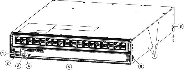
The following figure shows the hardware features seen from the port side of the chassis.
|
1 |
Chassis LEDs |
5 |
36 40-Gigabit QSFP+ ports |
|
2 |
USB ports |
6 |
Screw holes (2) for attaching a front-mount bracket for 4-post racks (1 bracket on each of 2 sides) |
|
3 |
Out-of-band management port (RJ-45 port) |
7 |
Notch in both sides of the chassis for locking the power supply end of the chassis to the bottom support brackets |
|
4 |
Console port (RJ232 port) |
Ports
The switch chassis includes the following types of ports:
-
40-Gigabit QSFP+ interface ports (36)
-
Console port (1)
-
Out-of-band management port (1)
-
USB flash-memory ports (2)
The interface ports support QSFP+ transceivers. You use these ports to connect the switch to leaf switches in the ACI network that this switch belongs to. These ports are numbered 1 to 36 from left to right.
 Note |
To see which transceivers are supported by this switch, see http://www.cisco.com/c/en/us/support/interfaces-modules/transceiver-modules/products-device-support-tables-list.html. |
The console port enables you to perform the initial setup of the switch.
The out-of-band management port enables you to manage switch operations after you set up the switch.
If you need to download or upload switch configurations on a flash drive, you can use the flash drive in one of the two USB ports.
Fan Modules
The switch supports two fan modules, which provide port-side intake or port-side exhaust airflow for cooling. You can hot swap one of the fan modules during operations but must replace it within one minute. If you cannot replace the fan module within one minute, then it is best to leave the failed fan module in the chassis until you are ready to replace it.
The fan modules are labeled FAN 1 on the left and FAN 2 on the right.
Note |
The switch must run with all of its power supply and fan modules taking in cooling air from a cold aisle and exhausting to a hot aisle. If they take in air from the hot aisle, the switch can overheat and shut down. All fan and power supply modules must use the same direction of airflow. |
Power Supply Modules
The switch has two power supply slots labeled PS1 on the left and PS2 on the right. You can mix any of the following power supplies in those slots:
-
1200-W port-side intake AC power supply with burgundy coloring (N9K-PAC-1200W)
-
1200-W port-side exhaust AC power supply with blue coloring (N9K-PAC-1200W-B)
-
930-W DC power supplies with green coloring for port-side intake airflow (UCSC-PSU-930WDC)
-
930-W DC power supplies with gray coloring for port-side exhaust airflow (UCS-PSU-6332-DC)
The switch requires one power supply for its operations and a second power supply for power redundancy. You can hot swap one of the power supplies during operations but otherwise must always have two power supplies (or one power supply and one blank faceplate) installed in the chassis to maintain the designed airflow.
 Caution |
The switch must run with all of its power supply and fan modules taking in cooling air from a cold aisle and exhausting to a hot aisle. If they take in air from the hot aisle, the switch can overheat and shut down. All power supply and fan modules must use the same direction of airflow. |
 Feedback