Powering on the Switch
This chapter describes how to connect the power modules in the chassis and to power on the switch.
The documentation set for this product strives to use bias-free language. For the purposes of this documentation set, bias-free is defined as language that does not imply discrimination based on age, disability, gender, racial identity, ethnic identity, sexual orientation, socioeconomic status, and intersectionality. Exceptions may be present in the documentation due to language that is hardcoded in the user interfaces of the product software, language used based on RFP documentation, or language that is used by a referenced third-party product. Learn more about how Cisco is using Inclusive Language.
This chapter describes how to connect the power modules in the chassis and to power on the switch.
You can install an AC power module in the chassis. Ensure all power connection wiring conforms to the rules and regulations in the National Electrical Code (NEC) as well as local codes.
The chassis has a power assembly shelf that supports the following number of power trays:
Cisco 9804 chassis contains two power trays
Each power tray supports up to three AC power modules.
 Note |
Use only one kind of power tray and power module in the chassis. |
Note |
Use only the same capacity power module in the chassis. Do not mix different capacity power modules. |
HVAC power modules operate in the input range of 180 VAC to 305 VAC (nominal input level of 200 to 240 VAC, 277 VAC).
NXK-HV-6.3KW20A-A: Each 6.3 KW, 20A power module can supply up to 6.3 KW to the power tray when it’s supplied by two feeds (A and B). It can supply up to 3.15 KW with only one feed.
NXK-HV-6.3KW30A-A: Each 6.3 KW, 30A power module can supply up to 6.3 KW to the power tray when it’s supplied by two feeds (A and B). It can supply up to 4.8 KW with only one feed.
The HVAC power supply has 2 redundant input power lines. It can provide a power output of 6.3 kW from each input power line with 2 inputs operating, or provide 4.8 kW (30A) or 3.15 kW (20A) output from either input with one input operating. The HVAC power supply provides n+n or n+x line redundancy mode in a single power supply for the switch.
The HVAC power supply accepts a maximum of 305VAC or 400VDC input power.
If you are not using power redundancy or are using n+1 power redundancy, you can connect all the power supplies in the chassis to the same power grid on the rear end of each power tray. If you are using n+n power redundancy, connect one redundant grid to one of the power supply inputs and the other redundant grid to the other power supply input on the back of the power tray as shown for each power supply. To enable grid redundancy, you must connect the corresponding inlet of power supplies to the correct power grids. For example, first inlet of all PS slots correspond to Grid-A and second inlet of all PS slots correspond to Grid-B.
Turn off the power source at its circuit breaker.
Check that the power switch is set to the STANDBY (0) position on the power tray.
NXK-HV-6.3KW30A-A: The HVAC power sources are rated for 30A maximum input current.
NXK-HV-6.3KW20A-A: The HVAC power sources are rated for 20A maximum input current.
|
Step 1 |
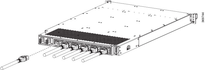
Choose your power supply (HVAC) and use a Saf-D-Grid power cable to connect to the power supply tray. |
||||
|
Step 2 |
For HVAC input, connect a Saf-D-Grid AC power cable to the Saf-D-Grid receptacle. 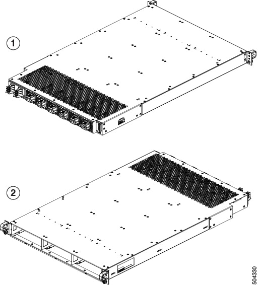
 |
||||
|
Step 3 |
Verify that the Saf-D-Grid plug is plugged in completely to secure the built-in retaining latch. |
||||
|
Step 4 |
Turn on the circuit breaker for the HVAC power source circuit.
|
||||
|
Step 5 |
Turn on the switch of the power shelf to turn on the system. |
Use the power redundancy-mode mode command to specify one of the following power modes:
For combined mode, include the combined keyword.
For n+1 redundancy mode, include the ps-redundant keyword.
For n+n redundancy mode, include the insrc-redundant keyword.
Example:
switch(config)# power redundancy-mode insrc-redundant
switch(config)#Note |
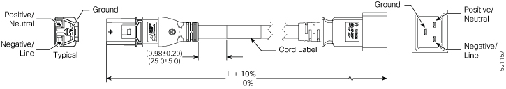
Always use the Saf-D-Grid connector toward the switch. |
|
Locale |
Part Number |
Cisco Part Number (CPN) |
Power Cord Set Rating |
Connector Part Number |
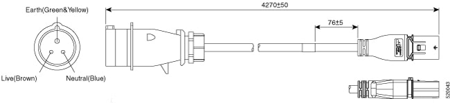
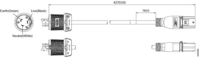
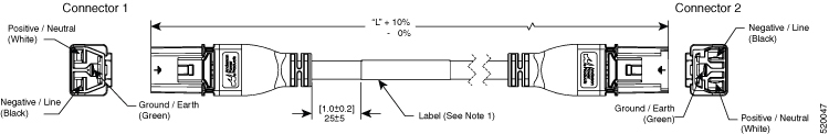
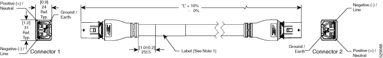
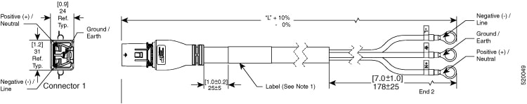
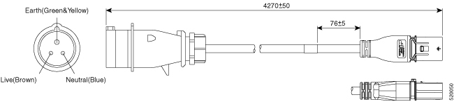
Power Cord Illustration |
|---|---|---|---|---|---|
|
North America |
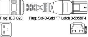
CAB-AC-20A-SG-C20 |
37-1653-01 |
20A, 250VAC |
Saf-D-Grid 3-5958P4 to IEC 60320 C20 |
Refer the figure in Power Cord Illustrations |
|
IEC/EU, US, CANADA, MEXICO, BRAZIL, NETHERLANDS, IRELAND, FRANCE, UK, GERMANY, SWITZERLAND, NORWAY, SPAIN, ITALY, SINGAPORE, CHINA, SOUTH AFRICA |
CAB-AC-20A-NA |
37-2126-01 |
20A, 250VAC |
Saf-D-Grid 3-5958P2 to IEC 60320 C20 |
Refer the figure in Power Cord Illustrations |
|
IEC/EU, AUSTRALIA/NEW ZEALAND, SWITZERLAND, ITALY, SOUTH AFRICA, ISRAEL, BRAZIL, ARGENTINA, INDIA |
CAB-AC-32A-ANZ, CAB-AC-32A-CHE, CAB-AC-32A-ITA, CAB-AC-32A-BRZ, CAB-AC-32A-ZAF, CAB-AC-32A-ISR, CAB-AC-32A-IND, CAB-AC-32A-ARG |
37-101007-01 |
32A, 250VAC |
Saf-D-Grid 3-5958P4 to Hubbell C332P6S Plug |
Refer the figure in Power Cord Illustrations |
|
NORTH AMERICA |
CAB-AC-30A-US1, CAB-AC-30A-US2 |
37-101008-01, 37-101009-01 |
30A, 250VAC |
Saf-D-Grid 3-5958P4 to VOLEX 174606 |
Refer the figure in Power Cord Illustrations |
|
NORTH AMERICA |
CAB-AC-30A-US3 |
37-101013-01 |
30A, 277VAC |
Saf-D-Grid 3-5958P4 to HBL2631 |
Refer the figure in Power Cord Illustrations |
|
NORTH AMERICA |
CAB-AC-30A-US4 |
37-101018-01 |
30A, 300VAC |
Saf-D-Grid 3-5958P4 to Saf-D-Grid 3-6074P30 |
Refer the figure in Power Cord Illustrations |
|
IEC/EU |
CAB-AC-32A-EU |
37-101019-01 |
32A, 300VAC |
Saf-D-Grid 3-5958P4 to Saf-D-Grid 3-6074P30 |
Refer the figure in Power Cord Illustrations |
|
IEC/EU |
CAB-DC-32A-EU1, CAB-DC-32A-EU2 |
37-101015-01, 37-101017-01 |
32A, 400VDC |
Saf-D-Grid 3-5958P4 to Saf-D-Grid 3-5958P4 |
Refer the figure in Power Cord Illustrations |
|
CHINA |
CAB-AC-32A-CHN |
37-101010-01 |
32A, 250VAC |
- |
Refer the figure in Power Cord Illustrations |
|
KOREA |
CAB-AC-32A-KOR |
37-101012-01 |
32A, 250VAC |
- |
Refer the figure in Power Cord Illustrations |
 Feedback