Configuring IP ACLs

This chapter describes how to configure IP access control lists (ACLs) on Cisco NX-OS devices.

Unless otherwise specified, the term IP ACL refers to IPv4 and IPv6 ACLs.

This chapter includes the following sections:

About ACLs

An ACL is an ordered set of rules that you can use to filter traffic. Each rule specifies a set of conditions that a packet must satisfy to match the rule. When the device determines that an ACL applies to a packet, it tests the packet against the conditions of all rules. The first matching rule determines whether the packet is permitted or denied. If there is no match, the device applies the applicable implicit rule. The device continues processing packets that are permitted and drops packets that are denied.

You can use ACLs to protect networks and specific hosts from unnecessary or unwanted traffic. For example, you could use ACLs to disallow HTTP traffic from a high-security network to the Internet. You could also use ACLs to allow HTTP traffic but only to specific sites, using the IP address of the site to identify it in an IP ACL.

ACL Types and Applications

The device supports the following types of ACLs for security traffic filtering:

IPv4 ACLs
The device applies IPv4 ACLs only to IPv4 traffic.
IPv6 ACLs
The device applies IPv6 ACLs only to IPv6 traffic.
MAC ACLs
The device applies MAC ACLs only to non-IP traffic.

IP and MAC ACLs have the following types of applications:

Port ACL
Filters Layer 2 traffic
Router ACL
Filters Layer 3 traffic
VLAN ACL
Filters VLAN traffic
VTY ACL
Filters virtual teletype (VTY) traffic

This table summarizes the applications for security ACLs.

Table 1. Security ACL Applications

Application

Supported Interfaces

Types of ACLs Supported

Port ACL

  • Layer 2 interfaces

  • Layer 2 Ethernet port-channel interfaces

When a port ACL is applied to a trunk port, the ACL filters traffic on all VLANs on the trunk port.

  • IPv4 ACLs

  • IPv4 ACLs with UDF-based match

  • IPv6 ACLs

  • IPv6 ACLs with UDF-based match

  • MAC ACLs

Router ACL

  • VLAN interfaces

  • Physical Layer 3 interfaces

  • Layer 3 Ethernet subinterfaces

  • Layer 3 Ethernet port-channel interfaces

  • Management interfaces

Note


You must enable VLAN interfaces globally before you can configure a VLAN interface.

  • IPv4 ACLs

  • IPv6 ACLs

VLAN ACL

  • VLANs

  • IPv4 ACLs

  • IPv6 ACLs

  • MAC ACLs

VTY ACL

  • VTYs

  • IPv4 ACLs

  • IPv6 ACLs

Order of ACL Application

When the device processes a packet, it determines the forwarding path of the packet. The path determines which ACLs that the device applies to the traffic. The device applies the ACLs in the following order:

  1. Port ACL

  2. Ingress VACL

  3. Ingress router ACL

  4. Ingress VTY ACL

  5. Egress VTY ACL

  6. Egress router ACL

  7. Egress VACL

If the packet is bridged within the ingress VLAN, the device does not apply router ACLs.
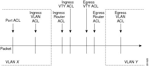
Figure 1. Order of ACL Application. The following figure shows the order in which the device applies ACLs.
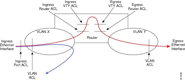
Figure 2. ACLs and Packet Flow .

The following figure shows where the device applies ACLs, depending upon the type of ACL. The red path indicates a packet sent to a destination on a different interface than its source. The blue path indicates a packet that is bridged within its VLAN.

The device applies only the applicable ACLs. For example, if the ingress port is a Layer 2 port and the traffic is on a VLAN that is a VLAN interface, a port ACL and a router ACL both can apply. In addition, if a VACL is applied to the VLAN, the device applies that ACL too.
About Rules

Rules are what you create, modify, and remove when you configure how an ACL filters network traffic. Rules appear in the running configuration. When you apply an ACL to an interface or change a rule within an ACL that is already applied to an interface, the supervisor module creates ACL entries from the rules in the running configuration and sends those ACL entries to the applicable I/O module. Depending upon how you configure the ACL, there may be more ACL entries than rules, especially if you implement policy-based ACLs by using object groups when you configure rules.

You can create rules in access-list configuration mode by using the permit or deny command. The device allows traffic that matches the criteria in a permit rule and blocks traffic that matches the criteria in a deny rule. You have many options for configuring the criteria that traffic must meet in order to match the rule.

This section describes some of the options that you can use when you configure a rule.

Protocols for IP ACLs and MAC ACLs

IPv4, IPv6, and MAC ACLs allow you to identify traffic by protocol. For your convenience, you can specify some protocols by name. For example, in an IPv4 or IPv6 ACL, you can specify ICMP by name.

You can specify any protocol by number. In MAC ACLs, you can specify protocols by the EtherType number of the protocol, which is a hexadecimal number. For example, you can use 0x0800 to specify IP traffic in a MAC ACL rule.

In IPv4 and IPv6 ACLs, you can specify protocols by the integer that represents the Internet protocol number.

Source and Destination

In each rule, you specify the source and the destination of the traffic that matches the rule. You can specify both the source and destination as a specific host, a network or group of hosts, or any host. How you specify the source and destination depends on whether you are configuring IPv4 ACLs, IPv6 ACLs, or MAC ACLs.

Implicit Rules for IP and MAC ACLs

IP and MAC ACLs have implicit rules, which means that although these rules do not appear in the running configuration, the device applies them to traffic when no other rules in an ACL match. When you configure the device to maintain per-rule statistics for an ACL, the device does not maintain statistics for implicit rules.

All IPv4 ACLs include the following implicit rule:

deny ip any any


This implicit rule ensures that the device denies unmatched IP traffic.

All IPv6 ACLs include the following implicit rule:

deny ipv6 any any

This implicit rule ensures that the device denies unmatched IPv6 traffic.


Note


IPv6 nd-na, nd-ns, router-advertisement, and router-solicitation packets will not be permitted as the implicit permit rules on IPv6 ACL. You must add the following rules explicitly to allow them:

  • permit icmp any any nd-na
  • permit icmp any any nd-ns
  • permit icmp any any router-advertisement
  • permit icmp any any router-solicitation

All MAC ACLs include the following implicit rule:

deny any any protocol 

This implicit rule ensures that the device denies the unmatched traffic, regardless of the protocol specified in the Layer 2 header of the traffic.

Additional Filtering Options

You can identify traffic by using additional options. These options differ by ACL type. The following list includes most but not all additional filtering options:

  • IPv4 ACLs support the following additional filtering options:

    • Differentiated Services Code Point (DSCP) value

    • Established TCP connections

    • Layer 4 protocol

    • TCP and UDP ports

    • TCP packets with the ACK, FIN, PSH, RST, SYN, or URG bit set

  • IPv6 ACLs support the following additional filtering options:

    • Differentiated Services Code Point (DSCP) value

    • Encapsulating Security Payload

    • Established TCP connections

    • Layer 4 protocol

    • Payload Compression Protocol

    • Stream Control Transmission Protocol (SCTP)

    • SCTP, TCP, and UDP ports

    • TCP packets with the ACK, FIN, PSH, RST, SYN, or URG bit set

  • MAC ACLs support the following additional filtering options:

    • Class of Service (CoS)

    • Layer 3 protocol (Ethertype)

    • VLAN ID

Sequence Numbers

The device supports sequence numbers for rules. Every rule that you enter receives a sequence number, either assigned by you or assigned automatically by the device. Sequence numbers simplify the following ACL tasks:

Adding new rules between existing rules

By specifying the sequence number, you specify where in the ACL a new rule should be positioned. For example, if you need to insert a rule between rules numbered 100 and 110, you could assign a sequence number of 105 to the new rule.

Removing a rule

Without using a sequence number, removing a rule requires that you enter the whole rule, as follows:

switch(config-acl)# no permit tcp 10.0.0.0/8 any

However, if the same rule had a sequence number of 101, removing the rule requires only the following command:

switch(config-acl)# no 101
Moving a rule

With sequence numbers, if you need to move a rule to a different position within an ACL, you can add a second instance of the rule using the sequence number that positions it correctly, and then you can remove the original instance of the rule. This action allows you to move the rule without disrupting traffic.

If you enter a rule without a sequence number, the device adds the rule to the end of the ACL and assigns a sequence number that is 10 greater than the sequence number of the preceding rule to the rule. For example, if the last rule in an ACL has a sequence number of 225 and you add a rule without a sequence number, the device assigns the sequence number 235 to the new rule.

In addition, Cisco NX-OS allows you to reassign sequence numbers to rules in an ACL. Resequencing is useful when an ACL has rules numbered contiguously, such as 100 and 101, and you need to insert one or more rules between those rules.

Logical Operators and Logical Operation Units

IP ACL rules for TCP and UDP traffic can use logical operators to filter traffic based on port numbers. Cisco NX-OS supports logical operators in only the ingress direction.

The device stores operator-operand couples in registers called logical operator units (LOUs). The LOU usage for each type of operator is as follows:

eq
Is never stored in an LOU
gt
Uses 1 LOU
lt
Uses 1 LOU
neq
Uses 1 LOU
range
Uses 1 LOU

Time Ranges

You can use time ranges to control when an ACL rule is in effect. For example, if the device determines that a particular ACL applies to traffic arriving on an interface, and a rule in the ACL uses a time range that is not in effect, the device does not compare the traffic to that rule. The device evaluates time ranges based on its clock.

When you apply an ACL that uses time ranges, the device updates the affected I/O module whenever a time range referenced in the ACL starts or ends. Updates that are initiated by time ranges occur on a best-effort priority. If the device is especially busy when a time range causes an update, the device may delay the update by up to a few seconds.

IPv4, IPv6, and MAC ACLs support time ranges. When the device applies an ACL to traffic, the rules in effect are as follows:

  • All rules without a time range specified

  • Rules with a time range that includes the second when the device applies the ACL to traffic

The device supports named, reusable time ranges, which allows you to configure a time range once and specify it by name when you configure many ACL rules. Time range names have a maximum length of 64 alphanumeric characters.

A time range contains one or more rules. The two types of rules are as follows:

Absolute

A rule with a specific start date and time, specific end date and time, both, or neither. The following items describe how the presence or absence of a start or end date and time affect whether an absolute time range rule is active:

  • Start and end date and time both specified—The time range rule is active when the current time is later than the start date and time and earlier than the end date and time.

  • Start date and time specified with no end date and time—The time range rule is active when the current time is later than the start date and time.

  • No start date and time with end date and time specified—The time range rule is active when the current time is earlier than the end date and time.

  • No start or end date and time specified—The time range rule is always active.

For example, you could prepare your network to allow access to a new subnet by specifying a time range that allows access beginning at midnight of the day that you plan to place the subnet online. You can use that time range in ACL rules that apply to the subnet. After the start time and date have passed, the device automatically begins applying the rules that use this time range when it applies the ACLs that contain the rules.

Periodic

A rule that is active one or more times per week. For example, you could use a periodic time range to allow access to a lab subnet only during work hours on weekdays. The device automatically applies ACL rules that use this time range only when the range is active and when it applies the ACLs that contain the rules.


Note


The order of rules in a time range does not affect how a device evaluates whether a time range is active. Cisco NX-OS includes sequence numbers in time ranges to make editing the time range easier.


Time ranges also allow you to include remarks, which you can use to insert comments into a time range. Remarks have a maximum length of 100 alphanumeric characters.

The device determines whether a time range is active as follows:

  • The time range contains one or more absolute rules—The time range is active if the current time is within one or more absolute rules.

  • The time range contains one or more periodic rules—The time range is active if the current time is within one or more periodic rules.

  • The time range contains both absolute and periodic rules—The time range is active if the current time is within one or more absolute rules and within one or more periodic rules.

When a time range contains both absolute and periodic rules, the periodic rules can only be active when at least one absolute rule is active.

Policy-Based ACLs

The device supports policy-based ACLs (PBACLs), which allow you to apply access control policies across object groups. An object group is a group of IP addresses or a group of TCP or UDP ports. When you create a rule, you specify the object groups rather than specifying IP addresses or ports.

Using object groups when you configure IPv4 or IPv6 ACLs can help reduce the complexity of updating ACLs when you need to add or remove addresses or ports from the source or destination of rules. For example, if three rules reference the same IP address group object, you can add an IP address to the object instead of changing all three rules.

PBACLs do not reduce the resources required by an ACL when you apply it to an interface. When you apply a PBACL or update a PBACL that is already applied, the device expands each rule that refers to object groups into one ACL entry per object within the group. If a rule specifies the source and destination both with object groups, the number of ACL entries created on the I/O module when you apply the PBACL is equal to the number of objects in the source group multiplied by the number of objects in the destination group.

The following object group types apply to port, router, policy-based routing (PBR), and VLAN ACLs:

IPv4 Address Object Groups

Can be used with IPv4 ACL rules to specify source or destination addresses. When you use the permit or deny command to configure a rule, the addrgroup keyword allows you to specify an object group for the source or destination.

IPv6 Address Object Groups

Can be used with IPv6 ACL rules to specify source or destination addresses. When you use the permit or deny command to configure a rule, the addrgroup keyword allows you to specify an object group for the source or destination.

Protocol Port Object Groups

Can be used with IPv4 and IPv6 TCP and UDP rules to specify source or destination ports. When you use the permit or deny command to configure a rule, the portgroup keyword allows you to specify an object group for the source or destination.


Note


Policy-based routing (PBR) ACLs do not support deny access control entries (ACEs) or deny commands to configure a rule.


Statistics and ACLs

The device can maintain global statistics for each rule that you configure in IPv4, IPv6, and MAC ACLs. If an ACL is applied to multiple interfaces, the maintained rule statistics are the sum of packet matches (hits) on all the interfaces on which that ACL is applied.


Note


The device does not support interface-level ACL statistics.


For each ACL that you configure, you can specify whether the device maintains statistics for that ACL, which allows you to turn ACL statistics on or off as needed to monitor traffic filtered by an ACL or to help troubleshoot the configuration of an ACL.

The device does not maintain statistics for implicit rules in an ACL. For example, the device does not maintain a count of packets that match the implicit deny ip any any rule at the end of all IPv4 ACLs. If you want to maintain statistics for implicit rules, you must explicitly configure the ACL with rules that are identical to the implicit rules.

About Per-Port Stats

Beginning Cisco NX-OS Release 9.2(2v), if required, you can get generate per-port stats even when you apply the same IPv4 or an IPv6 ACL to multiple interfaces.

Per-port stats have the following guidelines and limiations:

  • Per-port stats for ACLs are only applicable for physical ports.

  • Maximum three ingress TCAMS can be carved as per-port stats.

  • Maximum two egress TCAMS can be carved as per-port stats.

  • The maximum TCAM entries with per-port stats is 240 per IB.

  • Per-port stats are not supported on sub interfaces.

  • Per-port stats are always atomic.

Atomic ACL Updates

By default, when a supervisor module of a Cisco NX-OS device updates an I/O module with changes to an ACL, it performs an atomic ACL update. An atomic update does not disrupt traffic that the updated ACL applies to; however, an atomic update requires that an I/O module that receives an ACL update has enough available resources to store each updated ACL entry in addition to all pre-existing entries in the affected ACL. After the update occurs, the additional resources used for the update are freed. If the I/O module lacks the required resources, the device generates an error message and the ACL update to the I/O module fails.

If an I/O module lacks the resources required for an atomic update, you can disable atomic updates by using the no hardware access-list update atomic command; however, during the brief time required for the device to remove the preexisting ACL and implement the updated ACL, traffic that the ACL applies to is dropped by default.

If you want to permit all traffic that an ACL applies to while it receives a nonatomic update, use the hardware access-list update default-result permit command.

This example shows how to disable atomic updates to ACLs:

switch# config t 
switch(config)# no hardware access-list update atomic

This example shows how to permit affected traffic during a nonatomic ACL update:

switch# config t 
switch(config)# hardware access-list update default-result permit

This example shows how to revert to the atomic update method:

switch# config t 
switch(config)# no hardware access-list update default-result permit 
switch(config)# hardware access-list update atomic

Session Manager Support for IP ACLs

Session Manager supports the configuration of IP and MAC ACLs. This feature allows you to verify ACL configuration and confirm that the resources required by the configuration are available prior to committing them to the running configuration.

ACL TCAM Regions

You can change the size of the ACL ternary content addressable memory (TCAM) regions in the hardware.

On Cisco Nexus 3400-S Series switches, the egress TCAM size is 1.5K and is divided into two 256 slices and two 512 slices. The ingress TCAM size is 3.5K and is divided into six 256 slices and four 512 slices. A slice is the unit of allocation. A slice can be allocated to one region only.

You can create IPv4, IPv6, port ACLs, VLAN ACLs, and router ACLs, and you can match IPv4, IPv6 and MAC addresses for QoS. However, Cisco NX-OS cannot support all of them simultaneously. You must remove or reduce the size of the existing TCAM regions (TCAM carving) to enable the IPv6, MAC, or other desired TCAM regions. For every TCAM region configuration command, the system evaluates if the new change can be fit in the TCAM. If not, it reports an error, and the command is rejected. You must remove or reduce the size of existing TCAM regions to make room for new requirements.

ACL TCAM region sizes have the following guidelines and limitations:

  • When a VACL region is configured, it is configured with the same size in both the ingress and egress directions. If the region size cannot fit in either direction, the configuration is rejected.

  • The SUP region occupies 256 entries of 320 bits width.

The following table summarizes the regions that need to be configured for a given feature to work. The region sizes should be selected based on the scale requirements of a given feature.

Table 2. Features per ACL TCAM Region

Feature Name

Region Name

Port ACL

ifacl: For IPv4 port ACLs

ipv6-ifacl: For IPv6 port ACLs

mac-ifacl: For MAC port ACLs

Port QoS (QoS classification policy applied on Layer 2 ports or port channels)

ing-l2-qos: For classifying ingress Layer 2 packets

VACL (can be carved in both directions)

vacl: For IPv4 packets

ipv6-vacl: For IPv6 packets

mac-vacl: For non-IP packets

RACL

racl: For IPv4 RACLs

ipv6-racl: For IPv6 RACLs

e-racl: For egress IPv4 RACLs

e-ipv6-racl: For egress IPv6 RACLs

Layer 3 QoS (QoS classification policy applied on Layer 3 ports or port channels)

ing-l3-vlan-qos: For classifying IPv4 packets

Rx SPAN on 40G ports

span

SPAN filters

span

BFD, DHCP relay, or DHCPv6 relay

ing-sup

CoPP

ing-sup

System-managed ACLs

ing-sup

vPC convergence

Note

 
This region boosts the convergence times when a vPC link goes down and traffic needs to be redirected to the peer link.

vpc-convergence

Note

 
Setting this region size to 0 might affect the convergence times of vPC link failures.

Prerequisites for IP ACLs

IP ACLs have the following prerequisites:

  • You must be familiar with IP addressing and protocols to configure IP ACLs.

  • You must be familiar with the interface types that you want to configure with ACLs.

Guidelines and Limitations for IP ACLs

IP ACLs have the following configuration guidelines and limitations:

  • We recommend that you perform ACL configuration using the Session Manager. This feature allows you to verify ACL configuration and confirm that the resources that are required by the configuration are available before committing them to the running configuration. This recommendation is especially useful for ACLs that include more than 1000 rules. For more information about Session Manager, see the Cisco Nexus 3400-S NX-OS System Management Configuration Guide.

  • Duplicate ACL entries with different sequence numbers are allowed in the configuration. However, these duplicate entries are not programmed in the hardware access-list.

  • Only 62 unique ACLs can be configured. Each ACL takes one label. If the same ACL is configured on multiple interfaces, the same label is shared. If each ACL has unique entries, the ACL labels are not shared, and the label limit is 62. The combinations are as follows:

    • 31 unique PACLs of 5 bits and 31 unique Layer 2 QoS of 5 bits

    • 15 unique egress RACLs of 4 bits

    • 7 unique RACLs of 3 bits and 31 unique Layer 3 QoS of 5 bits

    • 15 unique VACLs of 4 bits

  • TCAM carving region can be either 128 or multiples of 128 for RACL + VACL.

  • VLAN QoS and egress QoS are not supported.

  • UDF with odd offset and 2-byte match is not supported.

  • ICMP type and code match are not supported.

  • Packet length match is not supported.

  • ACL statistics are not supported for CRC packets.

  • ACL log options are not supported.

  • TCP flags are not supported on an egress RACL in Cisco NX-OS Release 9.2(2t).

    Beginning Cisco NX-OS release 9.2(2v), TCP flags are supported on egress RACL.

  • ACLs with match DSCP are supported only in the pacl-all regions.

  • RACL does not affect sup-traffic.

  • VACL redirects are not supported.

  • Set COS and set DSCP combination is not supported for Layer 3 QoS.

  • Usually, ACL processing for IP packets occurs on the I/O modules, which use hardware that accelerates ACL processing. In some circumstances, processing occurs on the supervisor module, which can result in slower ACL processing, especially during processing that involves an ACL with many rules. Management interface traffic is always processed on the supervisor module. If IP packets in any of the following categories are exiting a Layer 3 interface, they are sent to the supervisor module for processing:

    • Packets that fail the Layer 3 maximum transmission unit check and therefore require fragmenting.

    • IPv4 packets that have IP options (additional IP packet header fields following the destination address field).

    • IPv6 packets that have extended IPv6 header fields.

    Policers prevent redirected packets from overwhelming the supervisor module.

  • When you apply an ACL that uses time ranges, the device updates the ACL entries whenever a time range that is referenced in an ACL entry starts or ends. Updates that are initiated by time ranges occur on a best-effort priority. If the device is especially busy when a time range causes an update, the device may delay the update by up to a few seconds.

  • To apply an IP ACL to a VLAN interface, you must have enabled VLAN interfaces globally. For more information about VLAN interfaces, see the Cisco Nexus 3400-S NX-OS Interfaces Configuration Guide.

  • The VTY ACL feature restricts all traffic for all VTY lines. You cannot specify different traffic restrictions for different VTY lines. Any router ACL can be configured as a VTY ACL.

  • When you apply an undefined ACL to an interface, the system treats the ACL as empty and permits all traffic.

  • IP tunnels do not support ACLs or QoS policies.

  • IPv4 and IPv6 ACL logging is not supported.

  • ACL logging for VACLs is not supported.

  • For Network Forwarding Engine (NFE)-enabled switches, ingress RACLs matching the outer header of the tunnel interface are not supported.

  • The switch hardware does not support range checks (Layer 4 operations) in the egress TCAM. Therefore, ACL and QoS policies with a Layer 4 operations-based classification must be expanded to multiple entries in the egress TCAM. Make sure to consider this limitation for egress TCAM space planning.

  • TCAM resources are shared in the following scenarios:

    • When a routed ACL is applied to multiple switched virtual interfaces (SVIs) in the ingress direction.

    • VACL (VLAN ACL) is applied to multiple VLANs.

  • Atomic ACL update is supported for all the ingress and egress ACL features except for the Multihop BFD and CoPP features.

  • Label sharing is supported only for the same policy on different interfaces within the same ASIC.

  • ACL label sharing is not supported for egress RACL and SPAN.

  • ACL statistics are not supported for the following:

    • BFD

    • DHCP - IPv4 and IPv6

  • Cisco Nexus 3400-S Series switches support the following on the ACLs:

    • Statistics support

    • Label sharing

  • When you enable the counters for the ACL TCAM entries using the hardware profile acl-stats modulexx command, the input discard field in the show interface is always zero.

  • IPv6 wildcard mask is not supported on Cisco Nexus 3400-S Series switches.

  • UDF is supported for both, IPv4 and IPv6 RACL and SPAN.

  • UDF is not supported on PACL.

  • TCAM regions for traffic storm control are carved by default.

  • Beginning with Cisco NX-OS Release 9.2(2v), UDF support is extended to IPv6 RACL and PACL.

  • Beginning Cisco NX-OS Release 9.2(2v), Remote Directory Memory Access (RDMA) and Explicit Congestion Notification (ECN) bits can be matched with ACLs only over UDF.

  • Beginning with Cisco NX-OS Release 9.2(2v), the following ACL TCAM regions are introduced:

    • Ingress PACL IPv4 and IPv6 (ifacl-all)

    • Ingress RACL IPv4 and IPv6 (racl-all)

  • ACEs with the same IPv4 or IPv6 addresses and different masks are not supported.

  • Beginning with Cisco NX-OS Release 9.3(5), the following ACL TCAM region is introduced:

    • Egress PACL IPv4 and IPv6 (e-ifacl-all)

  • Beginning with Cisco NX-OS Release 9.3(5), egress PACL is supported on Cisco Nexus 3408-S and 3432D-S switches. The following limitations are applicable:

    • ACL logging and redirect are not supported in the egress direction.

    • IP compression is not supported in the egress direction.

    • Egress PACL does not have per-interface label and is applied as per global policy. We recommend that the same egress PACL policy is applied on all Layer 2 interfaces.

    • If different egress PACL policies are applied to different Layer 2 ports, the TCAM programming behavior depends on the order in which the egress PACLs are configured.

    • TCP/UDP port range options are supported by ACE expansion. There is no LOU support.

  • Only a host match is supported when the IPv6 ACL is applied to the Layer 2 and Layer 3 interface for the traffic flowing in the specified direction.

Default Settings for IP ACLs

This table lists the default settings for IP ACL parameters.

Table 3. Default IP ACL Parameters

Parameters

Default

IP ACLs

No IP ACLs exist by default

IP ACL entries

1024

ACL rules

Implicit rules apply to all ACLs

Object groups

No object groups exist by default

Time ranges

No time ranges exist by default

Configuring IP ACLs

Creating an IP ACL

You can create an IPv4 ACL or IPv6 ACL on the device and add rules to it.

Before you begin

We recommend that you perform the ACL configuration using the Session Manager. This feature allows you to verify the ACL configuration and confirm that the resources that are required by the configuration are available before committing them to the running configuration. This feature is especially useful for ACLs that include more than about 1000 rules.

Procedure

  Command or Action Purpose

Step 1

configure terminal

Example:

switch# configure terminal
switch(config)#

Enters global configuration mode.

Step 2

Enter one of the following commands:

  • ip access-list name
  • ipv6 access-list name

Example:

switch(config)# ip access-list acl-01
switch(config-acl)#

Creates the IP ACL and enters IP ACL configuration mode. The name argument can be up to 64 characters.

Step 3

(Optional) fragments {permit-all | deny-all}

Example:

switch(config-acl)# fragments permit-all
(Optional)

Optimizes fragment handling for noninitial fragments. When a device applies to traffic an ACL that contains the fragments command, the fragments command only matches noninitial fragments that do not match any explicit permit or deny commands in the ACL.

Step 4

[sequence-number] {permit | deny} protocol {source-ip-prefix | source-ip-mask} {destination-ip-prefix | destination-ip-mask}

Example:

switch(config-acl)# 10 permit ipv6 1::1 2::2 3::3 4::4

Creates a rule in the IP ACL. You can create many rules. The sequence-number argument can be a whole number between 1 and 4294967295.

The permit and deny commands support many ways of identifying traffic.

For IPv4 and IPv6 access lists, you can specify a source and destination IPv4 or IPv6 prefix, which matches only on the first contiguous bits, or you can specify a source and destination IPv4 or IPv6 wildcard mask, which matches on any bit in the address.

Step 5

(Optional) statistics per-entry

Example:

switch(config-acl)# statistics per-entry
(Optional)

Specifies that the device maintains global statistics for packets that match the rules in the ACL.

Step 6

reload module xx

Example:

switch(config)# reload module 10

Reloads the switch.

Step 7

(Optional) Enter one of the following commands:

  • show ip access-lists name
  • show ipv6 access-lists name

Example:

switch(config-acl)# show ip access-lists acl-01
(Optional)

Displays the IP ACL configuration.

Step 8

(Optional) copy running-config startup-config

Example:

switch(config-acl)# copy running-config startup-config
(Optional)

Copies the running configuration to the startup configuration.

Changing an IP ACL

You can add and remove rules in an existing IPv4 or IPv6 ACL, but you cannot change existing rules. Instead, to change a rule, you can remove it and recreate it with the desired changes.

If you need to add more rules between existing rules than the current sequence numbering allows, you can use the resequence command to reassign sequence numbers.

Before you begin

We recommend that you perform ACL configuration using the Session Manager. This feature allows you to verify ACL configuration and confirm that the resources required by the configuration are available prior to committing them to the running configuration. This feature is especially useful for ACLs that include more than about 1000 rules.

Procedure

  Command or Action Purpose

Step 1

configure terminal

Example:

switch# configure terminal
switch(config)#

Enters global configuration mode.

Step 2

Enter one of the following commands:

  • ip access-list name
  • ipv6 access-list name

Example:

switch(config)# ip access-list acl-01
switch(config-acl)#

Enters IP ACL configuration mode for the ACL that you specify by name.

Step 3

(Optional) [sequence-number] {permit | deny} protocol source destination

Example:

switch(config-acl)# 100 permit ip 192.168.2.0/24 any
(Optional)

Creates a rule in the IP ACL. Using a sequence number allows you to specify a position for the rule in the ACL. Without a sequence number, the rule is added to the end of the rules. The sequence-number argument can be a whole number between 1 and 4294967295.

The permit and deny commands support many ways of identifying traffic.

Step 4

(Optional) [no] fragments {permit-all | deny-all}

Example:

switch(config-acl)# fragments permit-all
(Optional)

Optimizes fragment handling for noninitial fragments. When a device applies to traffic an ACL that contains the fragments command, the fragments command only matches noninitial fragments that do not match any explicit permit or deny commands in the ACL.

The no option removes fragment-handling optimization.

Step 5

(Optional) no {sequence-number | {permit | deny} protocol source destination}

Example:

switch(config-acl)# no 80
(Optional)

Removes the rule that you specified from the IP ACL.

The permit and deny commands support many ways of identifying traffic.

Step 6

(Optional) [no] statistics per-entry

Example:

switch(config-acl)# statistics per-entry
(Optional)

Specifies that the device maintains global statistics for packets that match the rules in the ACL.

The no option stops the device from maintaining global statistics for the ACL.

Step 7

(Optional) Enter one of the following commands:

  • show ip access-lists name
  • show ipv6 access-lists name

Example:

switch(config-acl)# show ip access-lists acl-01
(Optional)

Displays the IP ACL configuration.

Step 8

(Optional) copy running-config startup-config

Example:

switch(config-acl)# copy running-config startup-config
(Optional)

Copies the running configuration to the startup configuration.

Creating a VTY ACL

You can configure a VTY ACL to control access to all IPv4 or IPv6 traffic over all VTY lines in the ingress or egress direction.

Before you begin

Set identical restrictions on all the virtual terminal lines because a user can connect to any of them.

We recommend that you perform ACL configuration using the Session Manager. This feature allows you to verify ACL configuration and confirm that the resources required by the configuration are available prior to committing them to the running configuration, which is especially useful for ACLs that include more than about 1000 rules.

Procedure

  Command or Action Purpose

Step 1

configure terminal

Example:

switch# configure terminal
switch(config)#

Enters global configuration mode.

Step 2

{ip | ipv6 } access-list name

Example:

switch(config)# ip access-list vtyacl

Creates an ACL and enters IP access list configuration mode for that ACL. The maximum length for the name argument is 64 characters.

Step 3

{permit | deny } protocol source destination [log ] [time-range time]

Example:

switch(config-ip-acl)# permit tcp any any

Creates an ACL rule that permits TCP traffic from and to the specified sources.

Step 4

exit

Example:

switch(config-ip-acl)# exit
switch(config)#

Exits IP access list configuration mode.

Step 5

line vty

Example:

switch(config)# line vty
switch(config-line)#

Specifies the virtual terminal and enters line configuration mode.

Step 6

{ip | ipv6 } access-class name {in | out }

Example:

switch(config-line)# ip access-class vtyacl out

Restricts incoming or outgoing connections to and from all VTY lines using the specified ACL. The maximum length for the name argument is 64 characters.

Step 7

(Optional) show {ip | ipv6 } access-lists

Example:

switch# show ip access-lists
(Optional)

Displays the configured ACLs, including any VTY ACLs.

Step 8

(Optional) copy running-config startup-config

Example:

switch# copy running-config startup-config
(Optional)

Copies the running configuration to the startup configuration.

Changing Sequence Numbers in an IP ACL

You can change all the sequence numbers assigned to the rules in an IP ACL.

Before you begin

We recommend that you perform ACL configuration using the Session Manager. This feature allows you to verify ACL configuration and confirm that the resources required by the configuration are available prior to committing them to the running configuration. This feature is especially useful for ACLs that include more than about 1000 rules.

Procedure

  Command or Action Purpose

Step 1

configure terminal

Example:

switch# configure terminal
switch(config)#

Enters global configuration mode.

Step 2

resequence {ip | ipv6} access-list name starting-sequence-number increment

Example:

switch(config)# resequence access-list ip acl-01 100 10

Assigns sequence numbers to the rules contained in the ACL, where the first rule receives the starting sequence number that you specify. Each subsequent rule receives a number larger than the preceding rule. The difference in numbers is determined by the increment that you specify. The starting-sequence-number argument and the increment argument can be a whole number between 1 and 4294967295.

Step 3

(Optional) show ip access-lists name

Example:

switch(config)# show ip access-lists acl-01
(Optional)

Displays the IP ACL configuration.

Step 4

(Optional) copy running-config startup-config

Example:

switch(config)# copy running-config startup-config
(Optional)

Copies the running configuration to the startup configuration.

Removing an IP ACL

You can remove an IP ACL from the device.

Before you begin

Ensure that you know whether the ACL is applied to an interface. The device allows you to remove ACLs that are currently applied. Removing an ACL does not affect the configuration of interfaces where you have applied the ACL. Instead, the device considers the removed ACL to be empty. Use the show ip access-lists command or the show ipv6 access-lists command with the summary keyword to find the interfaces that an IP ACL is configured on.

Procedure

  Command or Action Purpose

Step 1

configure terminal

Example:

switch# configure terminal
switch(config)#

Enters global configuration mode.

Step 2

Enter one of the following commands:

  • no ip access-list name
  • no ipv6 access-list name

Example:

switch(config)# no ip access-list acl-01

Removes the IP ACL that you specified by name from the running configuration.

Step 3

(Optional) Enter one of the following commands:

  • show ip access-lists name summary
  • show ipv6 access-lists name summary

Example:

switch(config)# show ip access-lists acl-01 summary
(Optional)

Displays the IP ACL configuration. If the ACL remains applied to an interface, the command lists the interfaces.

Step 4

(Optional) copy running-config startup-config

Example:

switch(config)# copy running-config startup-config
(Optional)

Copies the running configuration to the startup configuration.

Configuring ACL TCAM Region Sizes

You can change the size of the ACL ternary content addressable memory (TCAM) regions in the hardware.


Note


  • Once you apply a template , the hardware access-list tcam region command in this section will not work. You must uncommit the template in order to use the command.

  • For information on configuring QoS TCAM carving, see the Cisco Nexus 3400-S NX-OS Quality of Service Configuration Guide.


Procedure

  Command or Action Purpose

Step 1

configure terminal

Example:

switch# configure terminal
switch(config)#

Enters global configuration mode.

Step 2

[no] hardware access-list tcam region region tcam-size

Example:

switch(config)# hardware access-list tcam region ifacl 256

Changes the ACL TCAM region size.

You can use the no form of this command to revert to the default TCAM region size.

Step 3

copy running-config startup-config

Example:

switch(config)# copy running-config startup-config

Copies the running configuration to the startup configuration.

Step 4

(Optional) show hardware access-list tcam region

Example:

switch(config)# show hardware access-list tcam region
(Optional)

Displays the TCAM sizes that will be applicable on the next reload of the device.

Step 5

reload

Example:

switch(config)# reload

Reloads the device.

Note

 
The new size values are effective only after you enter copy running-config startup-config + reload or reload all line card modules.

Example

The following example shows how to change the size of the RACL TCAM region on a Cisco Nexus 3400-S Series switch:

switch(config)# hardware access-list tcam region racl 256 
[SUCCESS] New tcam size will be applicable only at boot time. 
You need to 'copy run start' and 'reload'
switch(config)# copy running-config startup-config 
switch(config)# reload 
WARNING: This command will reboot the system 
Do you want to continue? (y/n) [n] y

This example shows how to display the TCAM region sizes to verify your changes:

switch(config)# show hardware access-list tcam region
IPV4 PACL [ifacl] size = 0
IPV6 PACL [ipv6-ifacl] size = 0
MAC PACL [mac-ifacl] size = 0
IPV4 VACL [vacl] size = 0
IPV6 VACL [ipv6-vacl] size = 0
MAC VACL [mac-vacl] size = 0
IPV4 RACL [racl] size = 256
IPV6 RACL [ipv6-racl] size = 0
Egress IPV4 RACL [e-racl] size = 0
Egress IPV6 RACL [e-ipv6-racl] size = 0
SPAN [span] size = 0
VPC Convergence/ES-Multi Home [vpc-convergence] size = 0
Ingress L2 QOS [ing-l2-qos] size = 0
Ingress L3/VLAN QOS [ing-l3-vlan-qos] size = 128
Ingress SUP [ing-sup] size = 256
Egress L2 QOS [egr-l2-qos] size = 0
Egress L3/VLAN QOS [egr-l3-vlan-qos] size = 0 

This example shows how to revert to the default RACL TCAM region size:

switch(config)# no hardware profile tcam region racl 512
[SUCCESS] New tcam size will be applicable only at boot time.
You need to 'copy run start' and 'reload'
switch(config)# copy running-config startup-config
switch(config)# reload
WARNING: This command will reboot the system
Do you want to continue? (y/n) [n] y
 

Configuring TCAM Carving

The default TCAM region configuration varies by platform and does not accommodate all TCAM regions. To enable any desired regions, you must decrease the TCAM size of one region and then increase the TCAM size for the desired region.


Note


For information on configuring QoS TCAM carving, see the Cisco Nexus 3400-S NX-OS Quality of Service Configuration Guide.

The following tables list the default sizes for the ingress and egress TCAM regions.

Table 4. Default TCAM Region Configuration (Ingress)
Region Name Size Width Total Size

IPv4 RACL

256

160 bits

512 (80 bits)

Layer 3 QoS

128

320 bits

512 (80 bits)

System

256

320 bits

1024 (80 bits)


Attention


To keep all modules synchronized, you must reload all line card modules or enter copy running-config startup-config + reload to reload the device. Multiple TCAM region configurations require only a single reload. You can wait until you complete all of your TCAM region configurations before you reload the device.

Depending on the configuration, you might exceed the TCAM size or run out of slices.

If you exceed the 1K ingress limit for all TCAM regions when you configure a TCAM region, the following message appears:
ERROR: Aggregate TCAM region configuration exceeded the available Ingress TCAM space. Please re-configure.
If you exceed the 1K egress limit for all TCAM regions when you configure a TCAM region, the following message appears:
ERROR: Aggregate TCAM region configuration exceeded the available Egress TCAM space. Please re-configure.

If TCAM for a particular feature is not configured and you try to apply a feature that requires TCAM carving, the following message appears:

 ERROR: Module x  returned status: TCAM region is not configured. Please configure TCAM
region and retry the command.

Configuring UDF-Based Router ACLs

This feature enables the device to match on user-defined fields (UDFs) and to apply the matching packets to IPv4 and IPv6 RACLs.

Procedure

  Command or Action Purpose

Step 1

configure terminal

Example:

switch# configure terminal
switch(config)#

Enters global configuration mode.

Step 2

udf udf-name offset-base offset length

Example:

switch(config)# udf pktoff10 packet-start 10 2

Example:

switch(config)# udf pktoff10 header outer l3 20 2

Defines the UDF as follows:

  • udf-name—Specifies the name of the UDF. You can enter up to 16 alphanumeric characters for the name.

  • offset-base—Specifies the UDF offset base as follows, where header is the packet header to consider for the offset: {packet-start | header {outer | inner {l3 | l4}}} .

  • offset—Specifies the number of bytes offset from the offset base. To match the first byte from the offset base (Layer 3/Layer 4 header), configure the offset as 0.

  • length—Specifies the number of bytes from the offset. Only 1 or 2 bytes are supported. To match additional bytes, you must define multiple UDFs.

You can define multiple UDFs, but Cisco recommends defining only required UDFs.

Step 3

hardware access-list tcam region racl qualify {udf udf-name } | v6udf v6udf-name

Example:

switch(config)# hardware access-list tcam region racl qualify udf pktoff10

Attaches the UDFs to the racl TCAM region, which applies to IPv4 or IPv6 router ACLs.

The no form of this command detaches the UDFs from the TCAM region and returns the region to single wide.

Note

 
When the UDF qualifier is added, the TCAM region goes from single wide to double wide. Make sure enough free space is available; otherwise, this command will be rejected. If necessary, you can reduce the TCAM space from unused regions and then re-enter this command. For more information, see Configuring ACL TCAM Region Sizes.

Step 4

copy running-config startup-config

Example:

switch(config)# copy running-config startup-config

Saves the change persistently through reboots and restarts by copying the running configuration to the startup configuration.

Step 5

reload

Example:

switch(config)# reload

Reloads the device.

Note


Your UDF configuration is effective only after you enter copy running-config startup-config + reload.

Step 6

ip access-list udf-acl

Example:

switch(config)# ip access-list udfacl
switch(config-acl)#

Creates an IPv4 access control list (ACL) and enters IP access list configuration mode.

Step 7

Enter one of the following commands:

  • permit udf udf-name value mask
  • permit ip source destination udf udf-name value mask

Example:

switch(config-acl)# permit udf pktoff10 0x1234 0xffff

Example:

switch(config-acl)# permit ip any any udf pktoff10 0x1234 0xffff 

Configures the ACL to match only on UDFs (example 1) or to match on UDFs along with the current access control entries (ACEs) for the outer packet fields (example 2). The range for the value and mask arguments is from 0x0 to 0xffff.

A single ACL can have ACEs with and without UDFs together. Each ACE can have different UDF fields to match, or all ACEs can match for the same list of UDFs.

Step 8

(Optional) copy running-config startup-config

Example:

switch(config)# copy running-config startup-config
(Optional)

Copies the running configuration to the startup configuration.

Applying an IP ACL as a Router ACL

You can apply an IPv4 or IPv6 ACL to any of the following types of interfaces:

  • Physical Layer 3 interfaces and subinterfaces

  • Layer 3 Ethernet port-channel interfaces

  • VLAN interfaces

  • Management interfaces

ACLs applied to these interface types are considered router ACLs.


Note


Egress router ACLs are not supported on subinterfaces.


Before you begin

Ensure that the ACL you want to apply exists and that it is configured to filter traffic in the manner that you need for this application.

Procedure

  Command or Action Purpose

Step 1

configure terminal

Example:

switch# configure terminal
switch(config)#

Enters global configuration mode.

Step 2

Enter one of the following commands:

  • interface ethernet slot/port[. number]
  • interface port-channel channel-number
  • interface vlan vlan-id
  • interface mgmt port

Example:

switch(config)# interface ethernet 2/3
switch(config-if)#

Enters configuration mode for the interface type that you specified.

Step 3

Enter one of the following commands:

  • ip access-group access-list {in | out}
  • ipv6 traffic-filter access-list {in | out}

Example:

switch(config-if)# ip access-group acl1 in

Applies an IPv4 or IPv6 ACL to the Layer 3 interface for traffic flowing in the direction specified. You can apply one router ACL per direction.

Step 4

(Optional) show running-config aclmgr

Example:

switch(config-if)# show running-config aclmgr
(Optional)

Displays the ACL configuration.

Step 5

(Optional) copy running-config startup-config

Example:

switch(config-if)# copy running-config startup-config
(Optional)

Copies the running configuration to the startup configuration.

Applying an IP ACL as a Port ACL

You can apply an IPv4 or IPv6 ACL to a Layer 2 interface, which can be a physical port or a port channel. ACLs applied to these interface types are considered port ACLs.

Before you begin

Ensure that the ACL you want to apply exists and that it is configured to filter traffic in the manner that you need for this application.

Procedure

  Command or Action Purpose

Step 1

configure terminal

Example:

switch# configure terminal
switch(config)#

Enters global configuration mode.

Step 2

Enter one of the following commands:

  • interface ethernet slot/port
  • interface port-channel channel-number

Example:

switch(config)# interface ethernet 2/3
switch(config-if)#

Enters configuration mode for the interface type that you specified.

Step 3

Enter one of the following commands:

  • ip port access-group access-list in
  • ipv6 port traffic-filter access-list in

Example:

switch(config-if)# ip port access-group acl-l2-marketing-group in

Applies an IPv4 or IPv6 ACL to the interface or port channel. Only inbound filtering is supported with port ACLs. You can apply one port ACL to an interface.

Step 4

(Optional) show running-config aclmgr

Example:

switch(config-if)# show running-config aclmgr
(Optional)

Displays the ACL configuration.

Step 5

(Optional) copy running-config startup-config

Example:

switch(config-if)# copy running-config startup-config
(Optional)

Copies the running configuration to the startup configuration.

Applying an IP ACL as a VACL

You can apply an IP ACL as a VACL.

Configuring Per-Port Stats

Procedure

  Command or Action Purpose

Step 1

configure terminal

Example:

switch# configure terminal
switch(config)#

Enters global configuration mode.

Step 2

hardware access-list tcam region racl 128 per-port-stats

Example:

switch(config)# hardware access-list tcam region racl 128 per-port-stats

Configures the per-port status for ingress RACL.

Step 3

copy running-config startup-config

Example:

switch(config)# copy running-config startup-config

Copies the running configuration to the startup configuration.

Step 4

reload

Example:

switch(config)# reload

Reloads the device.

Verifying the IP ACL Configuration

To display IP ACL configuration information, perform one of the following tasks.

Command

Purpose

show hardware access-list tcam region

Displays the TCAM sizes that will be applicable on the next reload of the device.

show ip access-lists

Displays the IPv4 ACL configuration.

show ipv6 access-lists

Displays the IPv6 ACL configuration.

show running-config aclmgr [all]

Displays the ACL running configuration, including the IP ACL configuration and the interfaces to which IP ACLs are applied.

Note

 
This command displays the user-configured ACLs in the running configuration. The all option displays both the default (CoPP-configured) and user-configured ACLs in the running configuration.

show startup-config acllog

Displays the ACL log startup configuration.

show startup-config aclmgr [all]

Displays the ACL startup configuration.

Note

 
This command displays the user-configured ACLs in the startup configuration. The all option displays both the default (CoPP-configured) and user-configured ACLs in the startup configuration.

Monitoring and Clearing IP ACL Statistics

To monitor or clear IP ACL statistics, use one of the commands in this table.

Command

Purpose

show ip access-lists

Displays the IPv4 ACL configuration. If the IPv4 ACL includes the statistics per-entry command, the show ip access-lists command output includes the number of packets that have matched each rule.

show ipv6 access-lists

Displays IPv6 ACL configuration. If the IPv6 ACL includes the statistics per-entry command, then the show ipv6 access-lists command output includes the number of packets that have matched each rule.

clear ip access-list counters

Clears statistics for all IPv4 ACLs or for a specific IPv4 ACL.

clear ipv6 access-list counters

Clears statistics for all IPv6 ACLs or for a specific IPv6 ACL.

Configuration Examples for IP ACLs

The following example shows how to create an IPv4 ACL named acl-01 and apply it as a port ACL to Ethernet interface 2/1, which is a Layer 2 interface:

ip access-list acl-01
  permit ip 192.168.2.0/24 any 
interface ethernet 2/1
  ip port access-group acl-01 in

The following example shows how to create an IPv6 ACL named acl-120 and apply it as a router ACL to Ethernet interface 2/3, which is a Layer 3 interface:

ipv6 access-list acl-120
  permit tcp 2001:0db8:85a3::/48 2001:0db8:be03:2112::/64
  permit udp 2001:0db8:85a3::/48 2001:0db8:be03:2112::/64
  permit tcp 2001:0db8:69f2::/48 2001:0db8:be03:2112::/64
  permit udp 2001:0db8:69f2::/48 2001:0db8:be03:2112::/64 
interface ethernet 2/3
  ipv6 traffic-filter acl-120 in

The following example shows how to create a VTY ACL named single-source and apply it on input IP traffic over the VTY line. This ACL allows all TCP traffic through and drops all other IP traffic:

ip access-list single-source
		permit tcp 192.168.7.5/24 any
		exit
		line vty
		ip access-class single-source in
		show ip access-lists

The following example shows how to configure a UDF-based port ACL:

switch# configure terminal
switch(config)# hardware access-list tcam region racl 256
switch(config)# udf pktoff10 packet-start 10 2
switch(config)# udf pktoff20 packet-start 10 1
switch(config)# hardware access-list tcam region racl qualify udf pktoff10 pktoff20

switch# configure terminal
switch(config)# ip access-list udfacl
switch(config-acl)# statistics per-entry
switch(config-acl)# 10 permit ip any any udf pktoff10 0x1234 0xffff

switch# configure terminal
switch(config)# interface Ethernet1/1
switch(config-if)# ip access-group udfacl in
switch(config-if)# no switchport
switch(config-if)# no shutdown

The following example shows how to configure an egress PACL:

switch# configure terminal
switch(config)# hardware access-list tcam region e-ifacl-all 256
switch(config)# copy running-config startup-config
switch(config)# reload
switch(config)# ip access-list acl-01
switch(config-acl)# statistics per-entry
	10 permit ip 30.1.1.2/32 60.1.1.2/32
	20 permit ip 30.1.1.3/32 60.1.1.3/32
	30 permit ip 30.1.1.4/32 60.1.1.4/32
	40 permit ip 30.1.1.5/32 60.1.1.5/32
	50 permit ip 30.1.1.6/32 60.1.1.6/32
switch(config)# interface ethernet 2/2
switch(config-if)# witchport mode trunk
switch(config-if)# switchport trunk allowed vlan 20,120
switch(config-if)# ip port access-group EP_30 out
 

Configuring Object Groups

You can use object groups to specify source and destination addresses and protocol ports in IPv4 ACL and IPv6 ACL rules.

Session Manager Support for Object Groups

Session Manager supports the configuration of object groups. This feature allows you to create a configuration session and verify your object group configuration changes prior to committing them to the running configuration. For more information about Session Manager, see the Cisco Nexus 3400-S NX-OS System Management Configuration Guide.

Creating and Changing an IPv4 Address Object Group

You can create and change an IPv4 address group object.

Procedure

  Command or Action Purpose

Step 1

configure terminal

Example:

switch# configure terminal
switch(config)#

Enters global configuration mode.

Step 2

object-group ip address name

Example:

switch(config)# object-group ip address ipv4-addr-group-13
switch(config-ipaddr-ogroup)#

Creates the IPv4 address object group and enters IPv4 address object-group configuration mode.

Step 3

Enter one of the following commands:

  • [sequence-number] host IPv4-address
  • [sequence-number] IPv4-address/prefix-len
  • [sequence-number] IPv4-address network-wildcard

Example:

switch(config-ipaddr-ogroup)# host 10.99.32.6

Creates an entry in the object group. For each entry that you want to create, use the host command and specify a single host, or omit the host command to specify a network of hosts.

You can specify a prefix length for an IPv4 object group, which matches only on the first contiguous bits, or you can specify a wildcard mask, which matches on any bit in the address.

Step 4

Enter one of the following commands:

  • no [sequence-number]
  • no host IPv4-address
  • no IPv4-address/prefix-len
  • no IPv4-address network-wildcard

Example:

switch(config-ipaddr-ogroup)# no host 10.99.32.6

Removes an entry in the object group. For each entry that you want to remove from the object group, use the no form of the host command.

Step 5

(Optional) show object-group name

Example:

switch(config-ipaddr-ogroup)# show object-group ipv4-addr-group-13
(Optional)

Displays the object group configuration.

Step 6

(Optional) copy running-config startup-config

Example:

switch(config-ipaddr-ogroup)# copy running-config startup-config
(Optional)

Copies the running configuration to the startup configuration.

Creating and Changing an IPv6 Address Object Group

You can create and change an IPv6 address group object.

Procedure

  Command or Action Purpose

Step 1

configure terminal

Example:

switch# configure terminal
switch(config)#

Enters global configuration mode.

Step 2

object-group ipv6 address name

Example:

switch(config)# object-group ipv6 address ipv6-addr-group-A7
switch(config-ipv6addr-ogroup)#

Creates the IPv6 address object group and enters IPv6 address object-group configuration mode.

Step 3

Enter one of the following commands:

  • [sequence-number] host IPv6-address
  • [sequence-number] IPv6-address/prefix-len

Example:

switch(config-ipv6addr-ogroup)# host 2001:db8:0:3ab0::1

Creates an entry in the object group. For each entry that you want to create, use the host command and specify a single host, or omit the host command to specify a network of hosts.

You can specify a prefix length for an IPv6 object group, which matches only on the first contiguous bits.

Step 4

Enter one of the following commands:

  • no sequence-number
  • no host IPv6-address
  • no IPv6-address/prefix-len

Example:

switch(config-ipv6addr-ogroup)# no host 2001:db8:0:3ab0::1

Removes an entry from the object group. For each entry that you want to remove from the object group, use the no form of the host command.

Step 5

(Optional) show object-group name

Example:

switch(config-ipv6addr-ogroup)# show object-group ipv6-addr-group-A7
(Optional)

Displays the object group configuration.

Step 6

(Optional) copy running-config startup-config

Example:

switch(config-ipv6addr-ogroup)# copy running-config startup-config
(Optional)

Copies the running configuration to the startup configuration.

Creating and Changing a Protocol Port Object Group

You can create and change a protocol port object group.

Procedure

  Command or Action Purpose

Step 1

configure terminal

Example:

switch# configure terminal
switch(config)#

Enters global configuration mode.

Step 2

object-group ip port name

Example:

switch(config)# object-group ip port NYC-datacenter-ports
switch(config-port-ogroup)#

Creates the protocol port object group and enters port object-group configuration mode.

Step 3

[sequence-number] operator port-number [port-number]

Example:

switch(config-port-ogroup)# eq 80

Creates an entry in the object group. For each entry that you want to create, use one of the following operator commands:

  • eq—Matches only the port number that you specify.

  • gt—Matches port numbers that are greater than (and not equal to) the port number that you specify.

  • lt—Matches port numbers that are less than (and not equal to) the port number that you specify.

  • neq—Matches all port numbers except for the port number that you specify.

  • range—Matches the range of port numbers between and including the two port numbers that you specify.

Note


The range command is the only operator command that requires two port-number arguments.

Step 4

no {sequence-number | operator port-number [port-number]}

Example:

switch(config-port-ogroup)# no eq 80

Removes an entry from the object group. For each entry that you want to remove, use the no form of the applicable operator command.

Step 5

(Optional) show object-group name

Example:

switch(config-port-ogroup)# show object-group NYC-datacenter-ports
(Optional)

Displays the object group configuration.

Step 6

(Optional) copy running-config startup-config

Example:

switch(config-port-ogroup)# copy running-config startup-config
(Optional)

Copies the running configuration to the startup configuration.

Removing an Object Group

You can remove an IPv4 address object group, an IPv6 address object group, or a protocol port object group.

Procedure

  Command or Action Purpose

Step 1

configure terminal

Example:

switch# configure terminal
switch(config)#

Enters global configuration mode.

Step 2

no object-group {ip address | ipv6 address | ip port} name

Example:

switch(config)# no object-group ip address ipv4-addr-group-A7

Removes the specified object group.

Step 3

(Optional) show object-group

Example:

switch(config)# show object-group
(Optional)

Displays all object groups. The removed object group should not appear.

Step 4

(Optional) copy running-config startup-config

Example:

switch(config)# copy running-config startup-config
(Optional)

Copies the running configuration to the startup configuration.

Verifying the Object-Group Configuration

To display object-group configuration information, enter one of the following commands:

Command

Purpose

show object-group

Displays the object-group configuration.

show {ip | ipv6} access-lists name [expanded]

Displays expanded statistics for the ACL configuration.

show running-config aclmgr

Displays the ACL configuration, including object groups.

Configuring Time-Ranges

Session Manager Support for Time-Ranges

Session Manager supports the configuration of time ranges. This feature allows you to create a configuration session and verify your time-range configuration changes prior to committing them to the running configuration. For more information about Session Manager, see the Cisco Nexus 3400-S NX-OS System Management Configuration Guide.

Creating a Time-Range

You can create a time range on the device and add rules to it.

Procedure

  Command or Action Purpose

Step 1

configure terminal

Example:

switch# configure terminal
switch(config)#

Enters global configuration mode.

Step 2

time-range name

Example:

switch(config)# time-range workday-daytime
switch(config-time-range)#

Creates the time range and enters time-range configuration mode.

Step 3

(Optional) [sequence-number] periodic weekday time to [weekday] time

Example:

switch(config-time-range)# periodic monday 00:00:00 to friday 23:59:59
(Optional)

Creates a periodic rule that is in effect for one or more contiguous days between and including the specified start and end days and times.

Step 4

(Optional) [sequence-number] periodic list-of-weekdays time to time

Example:

switch(config-time-range)# periodic weekdays 06:00:00 to 20:00:00
(Optional)

Creates a periodic rule that is in effect on the days specified by the list-of-weekdays argument between and including the specified start and end times. The following keywords are also valid values for the list-of-weekdays argument:

  • daily —All days of the week.

  • weekdays —Monday through Friday.

  • weekend —Saturday through Sunday.

Step 5

(Optional) [sequence-number] absolute start time date [end time date]

Example:

switch(config-time-range)# absolute start 1:00 15 march 2013
(Optional)

Creates an absolute rule that is in effect beginning at the time and date specified after the start keyword. If you omit the end keyword, the rule is always in effect after the start time and date have passed.

Step 6

(Optional) [sequence-number] absolute [start time date] end time date

Example:

switch(config-time-range)# absolute end 23:59:59 31 may 2013
(Optional)

Creates an absolute rule that is in effect until the time and date specified after the end keyword. If you omit the start keyword, the rule is always in effect until the end time and date have passed.

Step 7

(Optional) show time-range name

Example:

switch(config-time-range)# show time-range workday-daytime
(Optional)

Displays the time-range configuration.

Step 8

(Optional) copy running-config startup-config

Example:

switch(config-time-range)# copy running-config startup-config
(Optional)

Copies the running configuration to the startup configuration.

Changing a Time-Range

You can add and remove rules in an existing time range. You cannot change existing rules. Instead, to change a rule, you can remove it and recreate it with the desired changes.

If you need to add more rules between existing rules than the current sequence numbering allows, you can use the resequence command to reassign sequence numbers.

Procedure

  Command or Action Purpose

Step 1

configure terminal

Example:

switch# configure terminal
switch(config)#

Enters global configuration mode.

Step 2

time-range name

Example:

switch(config)# time-range workday-daytime
switch(config-time-range)#

Enters time-range configuration mode for the specified time range.

Step 3

(Optional) [sequence-number] periodic weekday time to [weekday] time

Example:

switch(config-time-range)# periodic monday 00:00:00 to friday 23:59:59
(Optional)

Creates a periodic rule that is in effect for one or more contiguous days between and including the specified start and end days and times.

Step 4

(Optional) [sequence-number] periodic list-of-weekdays time to time

Example:

switch(config-time-range)# 100 periodic weekdays 05:00:00 to 22:00:00
(Optional)

Creates a periodic rule that is in effect on the days specified by the list-of-weekdays argument between and including the specified start and end times. The following keywords are also valid values for the list-of-weekdays argument:

  • daily —All days of the week.

  • weekdays —Monday through Friday.

  • weekend —Saturday through Sunday.

Step 5

(Optional) [sequence-number] absolute start time date [end time date]

Example:

switch(config-time-range)# absolute start 1:00 15 march 2013
(Optional)

Creates an absolute rule that is in effect beginning at the time and date specified after the start keyword. If you omit the end keyword, the rule is always in effect after the start time and date have passed.

Step 6

(Optional) [sequence-number] absolute [start time date] end time date

Example:

switch(config-time-range)# absolute end 23:59:59 31 may 2013
(Optional)

Creates an absolute rule that is in effect until the time and date specified after the end keyword. If you omit the start keyword, the rule is always in effect until the end time and date have passed.

Step 7

(Optional) no {sequence-number | periodic arguments . . . | absolute arguments. . .}

Example:

switch(config-time-range)# no 80
(Optional)

Removes the specified rule from the time range.

Step 8

(Optional) show time-range name

Example:

switch(config-time-range)# show time-range workday-daytime
(Optional)

Displays the time-range configuration.

Step 9

(Optional) copy running-config startup-config

Example:

switch(config-time-range)# copy running-config startup-config
(Optional)

Copies the running configuration to the startup configuration.

Removing a Time-Range

You can remove a time range from the device.

Before you begin

Ensure that you know whether the time range is used in any ACL rules. The device allows you to remove time ranges that are used in ACL rules. Removing a time range that is in use in an ACL rule does not affect the configuration of interfaces where you have applied the ACL. Instead, the device considers the ACL rule using the removed time range to be empty.

Procedure

  Command or Action Purpose

Step 1

configure terminal

Example:

switch# configure terminal
switch(config)#

Enters global configuration mode.

Step 2

no time-range name

Example:

switch(config)# no time-range daily-workhours

Removes the time range that you specified by name.

Step 3

(Optional) show time-range

Example:

switch(config-time-range)# show time-range
(Optional)

Displays the configuration for all time ranges. The removed time range should not appear.

Step 4

(Optional) copy running-config startup-config

Example:

switch# copy running-config startup-config
(Optional)

Copies the running configuration to the startup configuration.

Changing Sequence Numbers in a Time Range

You can change all the sequence numbers assigned to rules in a time range.

Procedure

  Command or Action Purpose

Step 1

configure terminal

Example:

switch# configure terminal
switch(config)#

Enters global configuration mode.

Step 2

resequence time-range name starting-sequence-number increment

Example:

switch(config)# resequence time-range daily-workhours 100 10
switch(config)#

Assigns sequence numbers to the rules contained in the time range, where the first rule receives the starting sequence number that you specify. Each subsequent rule receives a number larger than the preceding rule. The difference in numbers is determined by the increment that you specify.

Step 3

(Optional) show time-range name

Example:

switch(config)# show time-range daily-workhours
(Optional)

Displays the time-range configuration.

Step 4

(Optional) copy running-config startup-config

Example:

switch(config)# copy running-config startup-config
(Optional)

Copies the running configuration to the startup configuration.

Verifying the Time-Range Configuration

To display time-range configuration information, perform one of the following tasks.

Command

Purpose

show time-range

Displays the time-range configuration.

show running-config aclmgr

Displays ACL configuration, including all time ranges.