Configuring Local SPAN and ERSPAN

This chapter contains the following sections:

Information About ERSPAN

The Cisco NX-OS system supports the Encapsulated Remote Switching Port Analyzer (ERSPAN) feature on both source and destination ports. ERSPAN transports mirrored traffic over an IP network. The traffic is encapsulated at the source router and is transferred across the network. The packet is decapsulated at the destination router and then sent to the destination interface.

ERSPAN consists of an ERSPAN source session, routable ERSPAN generic routing encapsulation (GRE)-encapsulated traffic, and an ERSPAN destination session. You can separately configure ERSPAN source sessions and destination sessions on different switches. You can also configure ERSPAN source sessions to filter ingress traffic by using ACLs.

ERSPAN Sources

The interfaces from which traffic can be monitored are called ERSPAN sources. Sources designate the traffic to monitor and whether to copy ingress, egress, or both directions of traffic. ERSPAN sources include the following:
  • Ethernet ports and port channels.

  • VLANs—When a VLAN is specified as an ERSPAN source, all supported interfaces in the VLAN are ERSPAN sources.

ERSPAN source ports have the following characteristics:
  • A port configured as a source port cannot also be configured as a destination port.

  • ERSPAN does not monitor any packets that are generated by the supervisor, regardless of their source.

  • Ingress traffic at source ports can be filtered by using ACLs so that they mirror only those packets of information that match the ACL criteria.

ERSPAN Destinations

ERSPAN destination sessions capture packets sent by ERSPAN source sessions on Ethernet ports or port channels and send them to the destination port. Destination ports receive the copied traffic from ERSPAN sources.

ERSPAN destination sessions are identified by the configured source IP address and ERSPAN ID. This allows multiple source sessions to send ERSPAN traffic to the same destination IP and ERSPAN ID and allows you to have multiple sources terminating at a single destination simultaneously.

ERSPAN destination ports have the following characteristics:

  • A port configured as a destination port cannot also be configured as a source port.

  • Destination ports do not participate in any spanning tree instance or any Layer 3 protocols.

  • Ingress and ingress learning options are not supported on monitor destination ports.

  • Host Interface (HIF) port channels and fabric port channel ports are not supported as SPAN destination ports.

ERSPAN Sessions

You can create ERSPAN sessions that designate sources and destinations to monitor.

When configuring ERSPAN source sessions, you must configure the destination IP address. When configuring ERSPAN destination sessions, you must configure the source IP address. See ERSPAN Sources for the properties of source sessions and ERSPAN Destinations for the properties of destination sessions.


Note


Only two ERSPAN or SPAN source sessions can run simultaneously across all switches. Only 23 ERSPAN destination sessions can run simultaneously across all switches.

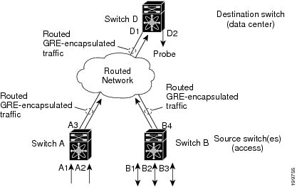
The following figure shows an ERSPAN configuration.

Figure 1. ERSPAN Configuration


Multiple ERSPAN Sessions

Although you can define up to 18 ERSPAN sessions, only a maximum of four ERSPAN or SPAN sessions can be operational simultaneously. If both receive and transmit sources are configured in the same session, only two ERSPAN or SPAN sessions can be operational simultaneously. You can shut down any unused ERSPAN sessions.


Note


The Cisco Nexus 34180YC platform switch supports a total of 32 sessions SPAN and ERSPAN sessions together configured on the switch and, all 32 can be active at the same time.


For information about shutting down ERSPAN sessions, see Shutting Down or Activating an ERSPAN Session.

High Availability

The ERSPAN feature supports stateless and stateful restarts. After a reboot or supervisor switchover, the running configuration is applied.

Prerequisites for ERSPAN

ERSPAN has the following prerequisite:

•You must first configure the Ethernet interfaces for ports on each device to support the desired ERSPAN configuration. For more information, see the Interfaces configuration guide for your platform.

Guidelines and Limitations for ERSPAN

ERSPAN has the following configuration guidelines and limitations:

  • Beginning with Cisco NX-OS Release 7.0(3)I4(1), the same source can be part of multiple sessions.

  • Beginning with Cisco NX-OS Release 7.0(3)I4(1), multiple ACL filters are supported on the same 
source.

  • Two ERSPAN destination sessions are not supported on Cisco Nexus 3000, 3100, and 3200 platform switches.

  • ERSPAN supports the following:

    • From 4 to 6 tunnels

    • Nontunnel packets

    • IP-in-IP tunnels

    • IPv4 tunnels (limited)

    • Cisco Nexus 3000 Series switches use a generic GRE ERSPAN header format for spanning packets matching ERSPAN source session. This format does not conform to the Cisco ERSPAN Type 1/2/3 header format. Cisco ASIC based platforms support ERSPAN termination and decapsulation only for ERSPAN packets conforming to Cisco ERSPAN encapsulation format Type. Hence, ERSPAN packets originating from Cisco Nexus 3000 Series switches to the local destination IP address of the CISCO ASIC based switch will not match the ERSPAN termination filter; If the destination IP address is also the local IP address on the Cisco ASIC platform, the ERSPAN packets are sent to software and dropped in software.

    • ERSPAN destination session type (however, support for decapsulating the ERSPAN packet is not available. The entire encapsulated packet is spanned to a front panel port at the ERSPAN terminating point.)

  • ERSPAN packets are dropped if the encapsulated mirror packet fails Layer 2 MTU checks.

  • There is a 112-byte limit for egress encapsulation. Packets that exceed this limit are dropped. This scenario might be encountered when tunnels and mirroring are intermixed.

  • ERSPAN sessions are shared with local sessions. A maximum of 18 sessions can be configured; however only a maximum of four sessions can be operational at the same time. If both receive and transmit sources are configured in the same session, only two sessions can be operational.

  • If you install Release NX-OS 5.0(3)U2(2), configure ERSPAN, and then downgrade to a lower version of software, the ERSPAN configuration is lost. This situation occurs because ERSPAN is not supported in versions before Release NX-OS 5.0(3)U2(2).

    For information about a similar SPAN limitation, see Guidelines and Limitations for SPAN.

  • ERSPAN and ERSPAN ACLs are not supported for packets that are generated by the supervisor.

  • ERSPAN and ERSPAN with ACL filtering are not supported for packets generated by the supervisor.

  • ACL filtering is supported only for Rx ERSPAN. Tx ERSPAN that mirrors all traffic egressed at the source interface.

  • ACL filtering is not supported for IPv6 and MAC ACLs because of TCAM width limitations.

  • If the same source is configured in more than one ERSPAN session, and each session has an ACL filter configured, the source interface will be programmed only for the first active ERSPAN session. The ACEs that belong to the other sessions will not have this source interface programmed.

  • If you configure an ERSPAN session and a local SPAN session (with filter access-group and allow-sharing option) to use the same source, the local SPAN session goes down when you save the configuration and reload the switch.

  • The drop action is not supported with the VLAN access-map configuration with the filter access-group for a monitor session. The monitor session goes into an error state if the VLAN access-map with a drop action is configured with the filter access-group in the monitor session.

  • Both permit and deny ACEs are treated alike. Packets that match the ACE are mirrored irrespective of whether they have a permit or deny entry in the ACL.

  • ERSPAN is not supported for management ports.

  • A destination port can be configured in only one ERSPAN session at a time.

  • You cannot configure a port as both a source and destination port.

  • A single ERSPAN session can include mixed sources in any combination of the following:

    • Ethernet ports or port channels but not subinterfaces.

    • VLANs or port channels, which can be assigned to port channel subinterfaces.

    • Port channels to the control plane CPU.


      Note


      ERSPAN does not monitor any packets that are generated by the supervisor, regardless of their source.
  • Destination ports do not participate in any spanning tree instance or Layer 3 protocols.

  • When an ERSPAN session contains source ports that are monitored in the transmit or transmit and receive direction, packets that these ports receive may be replicated to the ERSPAN destination port even though the packets are not actually transmitted on the source ports. Some examples of this behavior on source ports are as follows:

    • Traffic that results from flooding

    • Broadcast and multicast traffic

  • For VLAN ERSPAN sessions with both ingress and egress configured, two packets (one from ingress and one from egress) are forwarded from the destination port if the packets get switched on the same VLAN.

  • VLAN ERSPAN monitors only the traffic that leaves or enters Layer 2 ports in the VLAN.

  • When the Cisco Nexus 3000 series switch is the ERSPAN destination, GRE headers are not stripped off before sending mirrored packets out of the terminating point. Packets are sent along with the GRE headers as GRE packets and the original packet as the GRE payload.

  • You can view the SPAN/ERSPAN ACL statistics using the show monitor filter-list command. The output of the command displays all the entries along with the statistics from the SPAN TCAM. The ACL name is not printed, but only the entries are printed in the output. You can clear the statistics using the clear monitor filter-list statistics command. The output is similar to show ip access-list command. The Cisco Nexus 3000 series switch does not provide support per ACL level statistics. This enhancement is supported for both local SPAN and ERSPAN.

  • The traffic to and/or from the CPU is spanned. It is similar to any other interface SPAN. This enhancement is supported only in local SPAN. It is not supported with ACL source. The Cisco Nexus 3000 series switch does not span the packets with (RCPU.dest_port != 0) header that is sent out from the CPU.

  • For SPAN forward drop traffic, SPAN only the packets that get dropped due to various reasons in the forwarding plane. This enhancement is supported only for ERSPAN Source session. It is not supported along with SPAN ACL, Source VLAN, and Source interface. Three ACL entries are installed to SPAN dropped traffic. Priority can be set for the drop entries to have a higher/lower priority than the SPAN ACL entries and the VLAN SPAN entries of the other monitor sessions. By default, the drop entries have a higher priority.

  • SPAN UDF (User Defined Field) based ACL support

    • You can match any packet header or payload (certain length limitations) in the first 128 bytes of the packet.

    • You can define the UDFs with particular offset and length to match.

    • You can match the length as 1 or 2 bytes only.

    • Maximum of 8 UDFs are supported.

    • Additional UDF match criteria is added to ACL.

    • The UDF match criteria can be configured only for SPAN ACL. This enhancement is not supported for other ACL features, for example, RACL, PACL, and VACL.

    • Each ACE can have up to 8 UDF match criteria.

    • The UDF and http-redirect configuration should not co-exist in the same ACL.

    • The UDF names need to be qualified for the SPAN TCAM.

    • The UDFs are effective only if they are qualified by the SPAN TCAM.

    • The configuration for the UDF definition and the UDF name qualification in the SPAN TCAM require the use of copy r s command and reload.

    • The UDF match is supported for both Local SPAN and ERSPAN Src sessions.

    • The UDF name can have a maximum length of 16 characters.

    • The UDF offset starts from 0 (zero). If offset is specified as an odd number, 2 UDFs are used in the hardware for one UDF definition in the software. The configuration is rejected if the number of UDFs usage in the hardware goes beyond 8.

    • The UDF match requires the SPAN TCAM region to go double-wide. Therefore, you have to reduce the other TCAM regions' size to make space for SPAN.

    • The SPAN UDFs are not supported in tap-aggregation mode.

  • If a sup-eth source interface is configured in the erspan-src session, the acl-span cannot be added as a source into that session and vice-versa.

  • ERSPAN source and ERSPAN destination sessions must use dedicated loopback interfaces. Such loopback interfaces should not be having any control plane protocols.

Default Settings for ERSPAN

The following table lists the default settings for ERSPAN parameters.

Table 1. Default ERSPAN Parameters

Parameters

Default

ERSPAN sessions

Created in the shut state.

Configuring ERSPAN

Configuring an ERSPAN Source Session

You can configure an ERSPAN session on the local device only. By default, ERSPAN sessions are created in the shut state.

For sources, you can specify Ethernet ports, port channels, and VLANs. A single ERSPAN session can include mixed sources in any combination of Ethernet ports or VLANs.


Note


ERSPAN does not monitor any packets that are generated by the supervisor, regardless of their source.

Procedure

  Command or Action Purpose

Step 1

configure terminal

Example:

switch# config t
switch(config)#

Enters global configuration mode.

Step 2

monitor erspan origin ip-address ip-address global

Example:

switch(config)# monitor erspan origin 
ip-address 10.0.0.1 global

Configures the ERSPAN global origin IP address.

Step 3

no monitor session {session-number | all}

Example:

switch(config)# no monitor session 3

Clears the configuration of the specified ERSPAN session. The new session configuration is added to the existing session configuration.

Step 4

monitor session {session-number | all} type erspan-source

Example:

switch(config)# monitor session 3 type erspan-source
switch(config-erspan-src)#

Configures an ERSPAN source session.

Step 5

description description

Example:

switch(config-erspan-src)# description erspan_src_session_3

Configures a description for the session. By default, no description is defined. The description can be up to 32 alphanumeric characters.

Step 6

filter access-group acl-name

Example:

switch(config-erspan-src)# filter access-group acl1

Filters ingress traffic at source ports based on the ACL list. Only packets that match the access list are spanned. The acl-name is an IP access-list, but not an access-map.

Step 7

source {interface type [rx [allow-pfc] | tx | both] | vlan {number | range} [rx] | forward-drops rx [priority-low]}

Example:

switch(config-erspan-src)# source interface ethernet 2/1-3, ethernet 3/1 rx

Example:

switch(config-erspan-src)# source interface port-channel 2

Example:

switch(config-erspan-src)# source interface sup-eth 0 both

Example:

switch(config-monitor)# source interface ethernet 101/1/1-3

Configures the sources and traffic direction in which to copy packets. You can enter a range of Ethernet ports, a port channel, or a range of VLANs.

You can configure one or more sources, as either a series of comma-separated entries or a range of numbers. You can specify up to 128 interfaces. For information on the VLAN range, see the Cisco Nexus 3000 Series NX-OS Layer 2 Switching Configuration Guide.

You can specify the traffic direction to copy as ingress, egress, or both. The default direction is both.

The allow-pfc option initiates a span of the priority flow control (PFC) frames that are received on a port. PFC frames are allowed in the ingress pipeline instead of being dropped. If ERSPAN is configured for that port, those PFC frames are spanned to the appropriate egress interface. Ports configured with this option can also span normal data traffic.

As an alternative to configuring interfaces or VLANs as an ERSPAN source, you can configure ERSPAN to span the maximum number of forward packet drops possible in the ingress pipeline. Doing so can help you to analyze and isolate packet drops in the network. By default, the source forward-drops rx command captures packet drops for all ports on the network forwarding module. The priority-low option causes this ERSPAN access control entry (ACE) matching drop condition to take a lesser priority to any other ERSPAN ACEs configured by regular interface or VLAN ERSPAN ACLs.

Step 8

(Optional) Repeat Step 6 to configure all ERSPAN sources.

(Optional)

Step 9

destination ip ip-address

Example:

switch(config-erspan-src)# destination ip 10.1.1.1

Configures the destination IP address in the ERSPAN session. Only one destination IP address is supported per ERSPAN source session.

Step 10

(Optional) ip ttl ttl-number

Example:

switch(config-erspan-src)# ip ttl 25
(Optional)

Configures the IP time-to-live (TTL) value for the ERSPAN traffic. The range is from 1 to 255.

Step 11

(Optional) ip dscp dscp-number

Example:

switch(config-erspan-src)# ip dscp 42
(Optional)

Configures the differentiated services code point (DSCP) value of the packets in the ERSPAN traffic. The range is from 0 to 63.

Step 12

no shut

Example:

switch(config-erspan-src)# no shut
Enables the ERSPAN source session. By default, the session is created in the shut state.

Note

 
Only two ERSPAN source sessions can be running simultaneously.

Step 13

(Optional) show monitor session {all | session-number | range session-range}

Example:

switch(config-erspan-src)# show monitor session 3
(Optional)

Displays the ERSPAN session configuration.

Step 14

(Optional) show running-config monitor

Example:

switch(config-erspan-src)# show running-config monitor
(Optional)

Displays the running ERSPAN configuration.

Step 15

(Optional) show startup-config monitor

Example:

switch(config-erspan-src)# show startup-config monitor
(Optional)

Displays the ERSPAN startup configuration.

Step 16

(Optional) copy running-config startup-config

Example:

switch(config-erspan-src)# copy running-config startup-config
(Optional)

Copies the running configuration to the startup configuration.

Configuring SPAN Forward Drop Traffic for ERSPAN Source Session

Procedure

  Command or Action Purpose

Step 1

configure terminal

Example:

switch# config t
switch(config)#

Enters global configuration mode.

Step 2

monitor session {session-number | all} type erspan-source

Example:

switch(config)# monitor session 1 type erspan-source
switch(config-erspan-src)#

Configures an ERSPAN source session.

Step 3

vrf vrf-name

Example:

switch(config-erspan-src)# vrf default

Configures the VRF that the ERSPAN source session uses for traffic forwarding.

Step 4

destination ip ip-address

Example:

switch(config-erspan-src)# destination ip 10.1.1.1

Configures the destination IP address in the ERSPAN session. Only one destination IP address is supported per ERSPAN source session.

Step 5

source forward-drops rx [priority-low]

Example:

switch(config-erspan-src)# source forward-drops rx [priority-low]

Configures the SPAN forward drop traffic for the ERSPAN source session. When configured as a low priority, this SPAN ACE matching drop condition takes less priority over any other SPAN ACEs configured by the interface ACL SPAN or VLAN ACL SPAN. Without the priority-low keyword, these drop ACEs take high priority compared to the regular interface or the VLAN SPAN ACLs. The priority matters only when the packet matching drop ACEs and the interface/VLAN SPAN ACLs are configured.

Step 6

no shut

Example:

switch(config-erspan-src)# no shut

Enables the ERSPAN source session. By default, the session is created in the shut state.

Note

 
Only two ERSPAN source sessions can be running simultaneously.

Step 7

(Optional) show monitor session {all | session-number | range session-range}

Example:

switch(config-erspan-src)# show monitor session 3
(Optional)
Displays the ERSPAN session configuration.

Example

switch# config t
  switch(config)# monitor session 1 type erspan-source
  switch(config-erspan-src)# vrf default
  switch(config-erspan-src)# destination ip 40.1.1.1
  switch(config-erspan-src)# source forward-drops rx
  switch(config-erspan-src)# no shut
  switch(config-erspan-src)# show monitor session 1

switch# config t
  switch(config)# monitor session 1 type erspan-source
  switch(config-erspan-src)# vrf default
  switch(config-erspan-src)# destination ip 40.1.1.1
  switch(config-erspan-src)# source forward-drops rx  priority-low
  switch(config-erspan-src)# no shut
  switch(config-erspan-src)# show monitor session 1

Configuring an ERSPAN ACL

You can create an IPv4 ERSPAN ACL on the device and add rules to it.

Before you begin

To modify the DSCP value or the GRE protocol, you need to allocate a new destination monitor session. A maximum of four destination monitor sessions are supported.

Procedure

  Command or Action Purpose

Step 1

configure terminal

Example:

switch# configure terminal
switch(config)#

Enters global configuration mode.

Step 2

ip access-list acl-name

Example:

switch(config)# ip access-list erspan-acl
switch(config-acl)#

Creates the ERSPAN ACL and enters IP ACL configuration mode. The acl-name argument can be up to 64 characters.

Step 3

[sequence-number] {permit | deny} protocol source destination [set-erspan-dscp dscp-value] [set-erspan-gre-proto protocol-value]

Example:

switch(config-acl)# permit ip 192.168.2.0/24 any set-erspan-dscp 40 set-erspan-gre-proto 5555

Creates a rule in the ERSPAN ACL. You can create many rules. The sequence-number argument can be a whole number between 1 and 4294967295.

The permit and deny commands support many ways of identifying traffic.

The set-erspan-dscp option sets the DSCP value in the ERSPAN outer IP header. The range for the DSCP value is from 0 to 63. The DSCP value configured in the ERSPAN ACL overrides the value configured in the monitor session. If you do not include this option in the ERSPAN ACL, 0 or the DSCP value configured in the monitor session will be set.

The set-erspan-gre-proto option sets the protocol value in the ERSPAN GRE header. The range for the protocol value is from 0 to 65535. If you do not include this option in the ERSPAN ACL, the default value of 0x88be will be set as the protocol in the GRE header for ERSPAN-encapsulated packets.

Each access control entry (ACE) with the set-erspan-gre-proto or set-erspan-dscp action consumes one destination monitor session. A maximum of three ACEs with one of these actions is supported per ERSPAN ACL. For example, you can configure one of the following:
  • One ERSPAN session with an ACL having a maximum of three ACEs with the set-erspan-gre-proto or set-erspan-dscp action

  • One ERSPAN session with an ACL having two ACEs with the set-erspan-gre-proto or set-erspan-dscp action and one additional local or ERSPAN session

  • A maximum of two ERSPAN sessions with an ACL having one ACE with the set-erspan-gre-proto or set-erspan-dscp action

Step 4

(Optional) show ip access-lists name

Example:

switch(config-acl)# show ip access-lists erpsan-acl
(Optional)

Displays the ERSPAN ACL configuration.

Step 5

(Optional) show monitor session {all | session-number | range session-range} [brief]

Example:

switch(config-acl)# show monitor session 1
(Optional)

Displays the ERSPAN session configuration.

Step 6

(Optional) copy running-config startup-config

Example:

switch(config-acl)# copy running-config startup-config
(Optional)

Copies the running configuration to the startup configuration.

Configuring User Defined Field (UDF) Based ACL Support

You can configure User Defined Field (UDF) based ACL support on Cisco Nexus 3000 Series switches. See the following steps to configure ERSPAN based on UDF. See the Guidelines and Limitations for ERSPAN section for more information.

Procedure

  Command or Action Purpose

Step 1

switch# configure terminal

Enters global configuration mode.

Step 2

switch(config)# udf < udf -name> <packet start> <offset> <length>

Example:

(config)# udf udf1 packet-start 10 2
(config)# udf udf2 packet-start 50 2
Defines the UDF.

Note


You can define multiple UDFs but it is recommended to configure only the required UDFs. This configuration takes affect only after attaching the UDFs to a TCAM region and rebooting the box, as the UDFs are added to a region's qualifier set at TCAM carving time (boot up time).

Step 3

switch(config)# udf < udf -name> header <Layer3/Layer4> <offset> <length>

Example:

(config)# udf udf3 header outer l4 0 1
(config)# udf udf3 header outer l4 10 2
(config)# udf udf3 header outer l4 50 1

Defines the UDF.

Step 4

switch(config)# hardware profile tcam region span qualify udf <name1>…… <name8>

Example:

(config)# hardware profile tcam region span qualify udf udf1 udf2 udf3 udf4 udf5
[SUCCESS] Changes to UDF qualifier set will be applicable only after reboot.
You need to 'copy run start' and 'reload'
config)#

Configure UDF Qualification in SPAN TCAM. Add the UDFs to qualifier set for a TCAM region at TCAM carving time (happens at boot up time). The configuration allows maximum 4 UDFs that can be attached to a span region, all UDFs listed in a single command for a region. A new configuration for a region replaces the current configuration, but note that it needs a reboot for the configuration to come to the effect.

When the UDF qualifier is added to the SPAN TCAM, the TCAM region expands from single wide to double wide. Make sure enough free space (128 more single wide entries) is available for the expansion or else the command gets rejected. Re-enter the command after creating the space by reducing TCAM space from the unused regions. Once the UDFs are detached from SPAN/TCAM region using the no hardware profile tcam region span qualify udf <name1> ..<name8> command, the SPAN TCAM region is considered as a single wide entry.

Step 5

switch(config)# permit …… <regular ACE match criteria> udf <name1> < val > <mask> ..... <name8> < val > <mask>

Example:

(config)#  ip access-list test
10 permit ip any any udf udf1 0x1234 0xffff udf3 0x56 0xff
30 permit ip any any dscp af11 udf udf5 0x22 0x22
config)#

Configure an ACL with UDF match.

Step 6

switch(config)# show monitor session <session-number>

Example:

(config)# show monitor session 1
session 1
---------------
type              : erspan-source
state             : up
vrf-name          : default
destination-ip    : 40.1.1.1
ip-ttl            : 255
ip-dscp           : 0
acl-name          : test
origin-ip         : 100.1.1.10 (global)
source intf       :
    rx            : Eth1/20
    tx            : Eth1/20
    both          : Eth1/20
source VLANs      :
filter VLANs      : filter not specified
    rx            :
source fwd drops  :
egress-intf       : Eth1/23
switch#
config)#

Displays the ACL using the show monitor session <session-number> command. You can check if the SPAN TCAM region is carved or not using the BCM SHELL command.

Configuring IPv6 User Defined Field (UDF) on ERSPAN

You can configure IPv6 User Defined Field (UDF) on ERSPAN on Cisco Nexus 3000 Series switches. See the following steps to configure ERSPAN based on IPv6 UDF. See the Guidelines and Limitations for ERSPAN section for more information

Procedure

  Command or Action Purpose

Step 1

switch# configure terminal

Enters global configuration mode.

Step 2

switch(config)# udf < udf -name> <packet start> <offset> <length>

Example:

(config)# udf udf1 packet-start 10 2
(config)# udf udf2 packet-start 50 2
Defines the UDF.

Note


You can define multiple UDFs but it is recommended to configure only the required UDFs. This configuration takes affect only after attaching the UDFs to a TCAM region and rebooting the box, as the UDFs are added to a region's qualifier set at TCAM carving time (boot up time).

Step 3

switch(config)# udf < udf -name> header <Layer3/Layer4> <offset> <length>

Example:

(config)# udf udf3 header outer l4 0 1
(config)# udf udf3 header outer l4 10 2
(config)# udf udf3 header outer l4 50 1

Defines the UDF.

Step 4

switch(config)# hardware profile tcam region ipv6-span-l2 512

Example:

(config)# hardware profile tcam region ipv6-span-l2 512
Warning: Please save config and reload the system for the configuration to take effect.
config)#

Configure IPv6 on UDF on layer 2 ports. A new configuration for a region replaces the current configuration and you must reboot the switch for the configuration to come to the effect.

Step 5

switch(config)# hardware profile tcam region ipv6-span 512

Example:

(config)# hardware profile tcam region ipv6-span 512
Warning: Please save config and reload the system for the configuration to take effect.
config)#

Configure IPv6 on UDF on layer 3 ports. A new configuration for a region replaces the current configuration and you must reboot the switch for the configuration to come to the effect.

Step 6

switch(config)# hardware profile tcam region span spanv6 qualify udf <name1>…… <name8>

Example:

(config)# hardware profile tcam region spanv6 qualify udf udf1
[SUCCESS] Changes to UDF qualifier set will be applicable only after reboot.
You need to 'copy run start' and 'reload'
config)#

Configure UDF Qualification in SPAN for layer 3 ports. This enables the UDF match for ipv6-span TCAM region. Add the UDFs to qualifier set for a TCAM region at TCAM carving time (happens at boot up time). The configuration allows maximum of 2 IPv6 UDFs that can be attached to a SPAN region, all UDFs listed in a single command for a region. A new configuration for a region replaces the current configuration, but note that it needs a reboot for the configuration to come to the effect.

Step 7

switch(config)# hardware profile tcam region span spanv6-12 qualify udf <name1>…… <name8>

Example:

(config)# hardware profile tcam region spanv6-l2 qualify udf udf1
[SUCCESS] Changes to UDF qualifier set will be applicable only after reboot.
You need to 'copy run start' and 'reload'
config)#

Configure UDF Qualification in SPAN for layer 2 ports. This enables the UDF match for ipv6-span-12 TCAM region. Add the UDFs to qualifier set for a TCAM region at TCAM carving time (happens at boot up time). The configuration allows a maximum of 2 IPv6 UDFs that can be attached to a SPAN region, all UDFs listed in a single command for a region. A new configuration for a region replaces the current configuration, but note that it needs a reboot for the configuration to come to the effect.

Step 8

switch (config-erspan-src)# filter …… ipv6 access-group…. <aclname>…. <allow-sharing>

Example:

(config-erspan-src)# ipv6 filter access-group test
(config)# 

Configure a IPv6 ACL in SPAN and ERSPAN mode. You can have only one of “filter ip access-group” or “filter ipv6 access-group” configuration in one monitor session. If same source interface is part of a IPv4 and IPv6 ERSPAN ACL monitor session, the “allow-sharing” needs to be configured with the “filter [ipv6] access-group” in the monitor session configuration.

Step 9

switch(config)# permit …… <regular ACE match criteria> udf <name1> < val > <mask> ..... <name8> < val > <mask>

Example:

(config-erspan-src)# ipv6 access-list test
(config-ipv6-acl)# permit  ipv6 any  any  udf  udf1 0x1 0x0

Configure an ACL with UDF match.

Step 10

switch(config)# show monitor session <session-number>

Example:

(config)# show monitor session 1
session 1
---------------
type              : erspan-source
state             : up
vrf-name          : default
destination-ip    : 40.1.1.1
ip-ttl            : 255
ip-dscp           : 0
acl-name          : test
origin-ip         : 100.1.1.10 (global)
source intf       :
    rx            : Eth1/20
    tx            : Eth1/20
    both          : Eth1/20
source VLANs      :
filter VLANs      : filter not specified
    rx            :
source fwd drops  :
egress-intf       : Eth1/23
switch#
config)#

Displays the ACL using the show monitor session <session-number> command.

Shutting Down or Activating an ERSPAN Session

You can shut down ERSPAN sessions to discontinue the copying of packets from sources to destinations. Because only a specific number of ERSPAN sessions can be running simultaneously, you can shut down a session to free hardware resources to enable another session. By default, ERSPAN sessions are created in the shut state.

You can enable ERSPAN sessions to activate the copying of packets from sources to destinations. To enable an ERSPAN session that is already enabled but operationally down, you must first shut it down and then enable it. You can shut down and enable the ERSPAN session states with either a global or monitor configuration mode command.

Procedure

  Command or Action Purpose

Step 1

configuration terminal

Example:

switch# configuration terminal
switch(config)#

Enters global configuration mode.

Step 2

monitor session {session-range | all} shut

Example:

switch(config)# monitor session 3 shut

Shuts down the specified ERSPAN sessions. The session range is from 1-18. By default, sessions are created in the shut state. Four unidirectional sessions, or two bidirectional sessions can be active at the same time.

Note

 
  • In Cisco Nexus 5000 and 5500 platforms, two sessions can run simultaneously.

  • In Cisco Nexus 5600 and 6000 platforms, 16 sessions can run simultaneously.

Step 3

no monitor session {session-range | all} shut

Example:

switch(config)# no monitor session 3 shut
Resumes (enables) the specified ERSPAN sessions. The session range is from 1-18. By default, sessions are created in the shut state. Four unidirectional sessions, or two bidirectional sessions can be active at the same time.

Note


If a monitor session is enabled but its operational status is down, then to enable the session, you must first specify the monitor session shut command followed by the no monitor session shut command.

Step 4

monitor session session-number type erspan-source

Example:

switch(config)# monitor session 3 type erspan-source
switch(config-erspan-src)#

Enters the monitor configuration mode for the ERSPAN source type. The new session configuration is added to the existing session configuration.

Step 5

monitor session session-number type erspan-destination

Example:

switch(config-erspan-src)# monitor session 3 type erspan-destination

Enters the monitor configuration mode for the ERSPAN destination type.

Step 6

shut

Example:

switch(config-erspan-src)# shut

Shuts down the ERSPAN session. By default, the session is created in the shut state.

Step 7

no shut

Example:

switch(config-erspan-src)# no shut

Enables the ERSPAN session. By default, the session is created in the shut state.

Step 8

(Optional) show monitor session all

Example:

switch(config-erspan-src)# show monitor session all
(Optional)

Displays the status of ERSPAN sessions.

Step 9

(Optional) show running-config monitor

Example:

switch(config-erspan-src)# show running-config monitor
(Optional)

Displays the running ERSPAN configuration.

Step 10

(Optional) show startup-config monitor

Example:

switch(config-erspan-src)# show startup-config monitor
(Optional)

Displays the ERSPAN startup configuration.

Step 11

(Optional) copy running-config startup-config

Example:

switch(config-erspan-src)# copy running-config startup-config
(Optional)

Copies the running configuration to the startup configuration.

Verifying the ERSPAN Configuration

Use the following command to verify the ERSPAN configuration information:

Command

Purpose

show monitor session {all | session-number | range session-range}

Displays the ERSPAN session configuration.

show running-config monitor

Displays the running ERSPAN configuration.

show startup-config monitor

Displays the ERSPAN startup configuration.

Configuration Examples for ERSPAN

Configuration Example for an ERSPAN Source Session

The following example shows how to configure an ERSPAN source session:

switch# config t
switch(config)# interface e14/30
switch(config-if)# no shut
switch(config-if)# exit
switch(config)# monitor erspan origin ip-address 3.3.3.3 global
switch(config)# monitor session 1 type erspan-source
switch(config-erspan-src)# filter access-group acl1
switch(config-erspan-src)# source interface e14/30
switch(config-erspan-src)# ip ttl 16
switch(config-erspan-src)# ip dscp 5
switch(config-erspan-src)# vrf default
switch(config-erspan-src)# destination ip 9.1.1.2
switch(config-erspan-src)# no shut
switch(config-erspan-src)# exit
switch(config)# show monitor session 1

Configuration Example for an ERSPAN ACL

This example shows how to configure an ERSPAN ACL:

switch# configure terminal
switch(config)# ip access-list match_11_pkts
switch(config-acl)# permit ip 11.0.0.0 0.255.255.255 any
switch(config-acl)# exit
switch(config)# ip access-list match_12_pkts
switch(config-acl)# permit ip 12.0.0.0 0.255.255.255 any
switch(config-acl)# exit
switch(config)# vlan access-map erspan_filter 5
switch(config-access-map)# match ip address match_11_pkts
switch(config-access-map)# action forward
switch(config-access-map)# exit
switch(config)# vlan access-map erspan_filter 10
switch(config-access-map)# match ip address match_12_pkts
switch(config-access-map)# action forward
switch(config-access-map)# exit
switch(config)# monitor session 1 type erspan-source
switch(config-erspan-src)# filter access_group erspan_filter

Configuration Examples for UDF-Based ERSPAN

This example shows how to configure UDF-based ERSPAN to match on the inner TCP flags of an encapsulated IP-in-IP packet using the following match criteria:

  • Outer source IP address: 10.0.0.2

  • Inner TCP flags: Urgent TCP flag is set

  • Bytes: Eth Hdr (14) + Outer IP (20) + Inner IP (20) + Inner TCP (20, but TCP flags at 13th byte)

  • Offset from packet-start: 14 + 20 + 20 + 13 = 67

  • UDF match value: 0x20

  • UDF mask: 0xFF

udf udf_tcpflags packet-start 67 1
hardware access-list tcam region racl qualify udf udf_tcpflags
copy running-config startup-config
reload
ip access-list acl-udf
	 permit ip 10.0.0.2/32 any udf udf_tcpflags 0x20 0xff
monitor session 1 type erspan-source
  source interface Ethernet 1/1
  filter access-group acl-udf

This example shows how to configure UDF-based ERSPAN to match regular IP packets with a packet signature (DEADBEEF) at 6 bytes after a Layer 4 header start using the following match criteria:

  • Outer source IP address: 10.0.0.2

  • Inner TCP flags: Urgent TCP flag is set

  • Bytes: Eth Hdr (14) + IP (20) + TCP (20) + Payload: 112233445566DEADBEEF7788

  • Offset from Layer 4 header start: 20 + 6 = 26

  • UDF match value: 0xDEADBEEF (split into two-byte chunks and two UDFs)

  • UDF mask: 0xFFFFFFFF

udf udf_pktsig_msb header outer l3 26 2
udf udf_pktsig_lsb header outer l3 28 2
hardware access-list tcam region racl qualify udf udf_pktsig_msb udf_pktsig_lsb
copy running-config startup-config
reload
ip access-list acl-udf-pktsig
		permit udf udf_pktsig_msb 0xDEAD 0xFFFF udf udf_pktsig_lsb 0xBEEF 0xFFFF 
monitor session 1 type erspan-source
		source interface Ethernet 1/1
		filter access-group acl-udf-pktsig

Additional References

Related Documents

Related Topic

Document Title

ERSPAN commands: complete command syntax, command modes, command history, defaults, usage guidelines, and examples

Cisco Nexus NX-OS System Management Command Reference for your platform.