Configuring Segment Routing

This chapter contains information on how to configure segment routing.

About Segment Routing

Segment routing is a technique by which the path followed by a packet is encoded in the packet itself, similar to source routing. A node steers a packet through a controlled set of instructions, called segments, by prepending the packet with a segment routing header. Each segment is identified by a segment ID (SID) consisting of a flat unsigned 32-bit integer.

Border Gateway Protocol (BGP) segments, a subclass of segments, identify a BGP forwarding instruction. Prefix segments steer packets along the shortest path to the destination, using all available equal-cost multi-path (ECMP) paths.

Border Gateway Protocol - Link State (BGP-LS) is an extension to BGP for distributing the network’s Link-State (LS) topology model to external entities. BGP-LS advertise routing updates only when they occur which uses bandwidth more effectively. They advertise only the incremental change to all routers as a multicast update. They use variable length subnet masks, which are scalable and use addressing more efficiently.

The segment routing architecture is applied directly to the MPLS data plane.

BGP Prefix SID

In order to support segment routing, BGP requires the ability to advertise a segment identifier (SID) for a BGP prefix. A BGP prefix SID is always global within the segment routing BGP domain and identifies an instruction to forward the packet over the ECMP-aware best path computed by BGP to the related prefix. The BGP prefix SID identifies the BGP prefix segment.

Segment Routing Global Block

The segment routing global block (SRGB) is the range of local labels reserved for MPLS segment routing. The default label range is from 16000 to 23999.

SRGB is the local property of a segment routing node. Each node can be configured with a different SRGB value, and hence the absolute SID value associated to a BGP prefix segment can change from node to node.

The SRGB must be a proper subset of the dynamic label range and must not overlap the optional MPLS static label range. If dynamic labels in the configured or defaulted SRGB range already have been allocated, the configuration is accepted, and the existing dynamic labels that fall in the SRGB range will remain allocated to the original client. If the BGP router attempts to allocate one of these labels, the SRGB mapping fails, and the BGP router reverts to dynamic label allocation. A change to the SRGB range results in the clients deallocating their labels independent of whether the new range can be allocated.

High Availability for Segment Routing

In-service software upgrades (ISSUs) are minimally supported with BGP graceful restart. All states (including the segment routing state) must be relearned from the BGP router's peers. During the graceful restart period, the previously learned route and label state are retained.

BGP Prefix SID Deployment Example

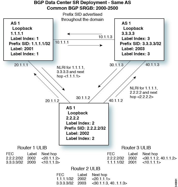
In the simple example below, all three routers are running iBGP and advertising Network Layer Reachability Information (NRLI) to one another. The routers are also advertising their loopback interface as the next hop, which provides the ECMP between routers 2.2.2.2 and 3.3.3.3.

Figure 1. BGP Prefix SID Simple Example

Guidelines and Limitations for Segment Routing

Segment routing has the following guidelines and limitations:

  • You can configure segment routing using Segment Routing Application (SR-APP) module. SR-APP is a separate internal process that handles all the CLIs related to segment routing. SR-APP reserves the SRGB range and for notifying the clients and it maintains SID mappings prefixes.

  • ISIS-SR is supported on Cisco Nexus 3172, Cisco Nexus 3132, Cisco Nexus C31128PQ-10GE and Cisco Nexus N3K-C3164Q-40GE switches.

  • Segment routing is supported only on Cisco Nexus 3100 Series switches that are running in N9K mode.

  • BGP allocates a SRGB label for iBGP route-reflector clients only when next-hop-self is in effect (for example, the prefix is advertised with the next hop being one of the local IP/IPv6 addresses on RR). When you have configured next-hop-self on a RR, the next hop is changed for the routes that are being affected (subject to route-map filtering).

  • Static MPLS, MPLS segment routing, and MPLS stripping cannot be enabled at the same time.

  • Because static MPLS, MPLS segment routing, and MPLS stripping are mutually exclusive, the only segment routing underlay for multi-hop BGP is single-hop BGP. iBGP multi-hop topologies with eBGP running as an overlay are not supported.

  • MPLS pop followed by a forward to a specific interface is not supported. The penultimate hop pop (PHP) is avoided by installing the Explicit NULL label as the out-label in the label FIB (LFIB) even when the control plane installs an IPv4 Implicit NULL label.

  • BGP labeled unicast and BGP segment routing are not supported for IPv6 prefixes.

  • BGP labeled unicast and BGP segment routing are not supported over tunnel interfaces (including GRE and VXLAN) or with vPC access interfaces.

  • MTU path discovery (RFC 2923) is not supported over MPLS label switched paths (LSPs) or segment routed paths.

  • The BGP configuration commands neighbor-down fib-accelerate and suppress-fib-pending are not supported for MPLS prefixes.

  • The uniform model as defined in RFC 2973 and RFC 3270 is not supported. Consequently, the IP DSCP bits are not copied into the imposed MPLS header.

  • Reconfiguration of the segment routing global block (SRGB) results in an automatic restart of the BGP process to update the existing URIB and ULIB entries. Traffic loss will occur for a few seconds, so you should not reconfigure the SRGB in production.

  • If the segment routing global block (SRGB) is set to a range but the route-map label-index delta value is outside of the configured range, the allocated label is dynamically generated. For example, if the SRGB is set to a range of 16000-23999 but a route-map label-index is set to 9000, the label is dynamically allocated.

  • For network scalability, Cisco recommends using a hierarchical routing design with multi-hop BGP for advertising the attached prefixes from a top-of-rack (TOR) or border leaf switch.

  • BGP sessions are not supported over MPLS LSPs or segment routed paths.

  • The Layer 3 forwarding consistency checker is not supported for MPLS routes.

  • Cisco Nexus 3000 switches support Link-State distribution and Egress Peer Engineering (EPE) using BGP.

  • Segment routing and SR-EVPN is supported on Cisco Nexus C31108PC-V, Cisco Nexus C31108TC-V and Cisco Nexus C3132Q-V switches.

Overview of BGP Egress Peer Engineering With Segment Routing

Cisco Nexus 3000 Series switches are often deployed in massive scale data centers (MSDCs). In such environments, there is a requirement to support BGP Egress Peer Engineering (EPE) with Segment Routing (SR).

Segment Routing (SR) leverages source routing. A node steers a packet through a controlled set of instructions, known as segments, by prepending the packet with an SR header. A segment can represent any topological or service-based instruction. SR allows steering a flow through any topological path or any service chain while maintaining per-flow state only at the ingress node of the SR domain. For this feature, the Segment Routing architecture is applied directly to the MPLS data plane.

In order to support Segment Routing, BGP requires the ability to advertise a Segment Identifier (SID) for a BGP prefix. A BGP-Prefix is always global within the SR or BGP domain and it identifies an instruction to forward the packet over the ECMP-aware best-path that is computed by BGP to the related prefix. The BGP-Prefix-SID is the identifier of the BGP prefix segment.

The SR-based Egress Peer Engineering (EPE) solution allows a centralized (SDN) controller to program any egress peer policy at ingress border routers or at hosts within the domain.

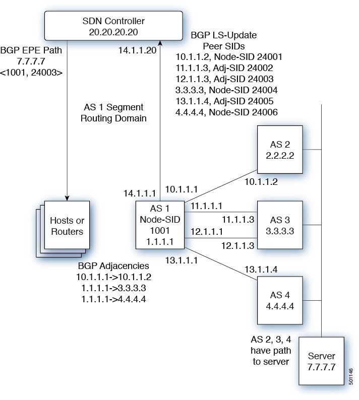
In the following example, all three routers run iBGP and they advertise NRLI to one another. The routers also advertise their loopback as the next-hop and it is recursively resolved. This provides an ECMP between the routers as displayed in the illustration.

Figure 2. Example of Egress Peer Engineering

The SDN controller receives the Segment IDs from the egress router 1.1.1.1 for each of its peers and adjacencies. It can then intelligently advertise the exit points to other routers and hosts within the controller’s routing domain. As displayed in the illustration, the BGP Network Layer Reachability Information (NLRI) contains both the Node-SID to the Router 1.1.1.1 and the Peer-Adjacency-SID 24003, indicating that the traffic to 7.7.7.7 should egress over 12.1.1.1->12.1.1.3.

Guidelines and Limitations for BGP Egress Peer Engineering

See the following guidelines and limitations for BGP Egress Peer Engineering:

  • BGP Egress Peer Engineering is only supported for IPv4 BGP peers. IPv6 BGP peers are not supported.

  • BGP Egress Peer Engineering is only supported in the default VPN Routing and Forwarding (VRF) instance.

  • Any number of Egress Peer Engineering (EPE) peers may be added to an EPE peer set. However, the installed resilient per-CE FEC is limited to 32 peers.

  • A given BGP neighbor can only be a member of a single peer-set. Peer-sets are configured. Multiple peer-sets are not supported. An optional peer-set name may be specified to add neighbor to a peer-set. The corresponding RPC FEC load-balances the traffic across all the peers in the peer-set. The peer-set name is a string that is a maximum length of 63 characters (64 NULL terminated). This length is consistent with the NX-OS policy name lengths. A peer can only be a member of a single peer-set.

  • Adjacencies for a given peer are not separately assignable to different peer-sets.

Configuring Segment Routing

Configuring Segment Routing Using Segment Routing Application

You can configure segment routing using the Segment Routing Application (SR-APP) module. SR-APP is a separate internal process that handles all the CLIs related to segment routing. SR-APP reserves the SRGB range and for notifying the clients and it maintains SID mappings prefixes. SR-APP is supported for the BGP and IS-IS protocols.

Complete the following steps to configure segment routing:

Before you begin

Ensure the following conditions are met before configuring Segment Routing using the Segment Routing Application (SR-APP).

  • The feature-set mpls and feature mpls segment-routing commands should be present for configuring the segment-routing mpls command.

  • The feature mpls segment-routing command starts the SR-APP process.

  • When segment-routing mpls is configured, SR state moves to SR_DISABLED and notifies the same to the clients. In this state, clients can allow protocol specific SR configurations but clients cannot do SID label bindings.

  • If the global block is configured, the specified range is used. Otherwise, the default 16000 – 23999 range is used. If the value is less than 16000, then that value will be automatically converted to 16000.

  • With the introduction of SR-APP, all configuration is done under segment-routing mpls and the prefix SID configuration is handled by SR-APP.

  • BGP now uses both set label-index <value> configuration and the new connected-prefix-sid-map CLI. In case of a conflict, the configuration in SR-APP is preferred.

SUMMARY STEPS

  1. configure terminal
  2. segment-routing mpls
  3. global-block <min> <max>
  4. connected-prefix-sid-map
  5. address-family ipv4
  6. <prefix>/<masklen>[index|absolute] <label>

DETAILED STEPS

  Command or Action Purpose
Step 1

configure terminal

Enters global configuration mode.

Step 2

segment-routing mpls

Activates the Segment Routing functionality

Step 3

global-block <min> <max>

Example:

global-block 201000 280000

Reserves the non-default SRGB range.

Step 4

connected-prefix-sid-map

Provides the SID label for the interface IP covered by the prefix-SID map.

Step 5

address-family ipv4

Enters global address family configuration mode for the IPv4 address family.

Step 6

<prefix>/<masklen>[index|absolute] <label>

Example:

2.1.1.5/32 absolute 201101 2.10.1.5/32 index 10001

The optional keywords index or absolute indicate whether the label value entered should be interpreted as an index into the SRGB or as an absolute value.

Example


switch# show running-config segment-routing
 
!Command: show running-config segment-routing
!Time: Fri Dec 22 12:51:59 2017
 
version 9.2(1)
segment-routing mpls
  global-block 201000 280000
  connected-prefix-sid-map
    address-family ipv4
      2.1.1.5/32 absolute 201101
      2.10.1.5/32 index 10001

Enabling MPLS Segment Routing

You can enable MPLS segment routing as long as mutually-exclusive MPLS features such as static MPLS are not enabled.

Before you begin

You must install and enable the MPLS feature set using the install feature-set mpls and feature-set mpls commands.

SUMMARY STEPS

  1. configure terminal
  2. [no] feature mpls segment-routing
  3. (Optional) show running-config | inc 'feature mpls segment-routing'
  4. (Optional) copy running-config startup-config

DETAILED STEPS

  Command or Action Purpose
Step 1

configure terminal

Example:

switch# configure terminal
switch(config)#

Enters global configuration mode.

Step 2

[no] feature mpls segment-routing

Example:

switch(config)# feature mpls segment-routing

Enables the MPLS segment routing feature. The no form of this command disables the MPLS segment routing feature.

Step 3

(Optional) show running-config | inc 'feature mpls segment-routing'

Example:

switch(config)# show running-config | inc 'feature mpls segment-routing'

(Optional)

Displays the status of the MPLS segment routing feature.

Step 4

(Optional) copy running-config startup-config

Example:

switch(config)# copy running-config startup-config
(Optional)

Copies the running configuration to the startup configuration.

Enabling MPLS on an Interface

You can enable MPLS on an interface for use with segment routing.

Before you begin

You must install and enable the MPLS feature set using the install feature-set mpls and feature-set mpls commands.

SUMMARY STEPS

  1. configure terminal
  2. interface type slot/port
  3. [no] mpls ip forwarding
  4. (Optional) copy running-config startup-config

DETAILED STEPS

  Command or Action Purpose
Step 1

configure terminal

Example:

switch# configure terminal
switch(config)#

Enters global configuration mode.

Step 2

interface type slot/port

Example:

switch(config)# interface ethernet 2/2
switch(config-if)#

Enters the interface configuration mode for the specified interface.

Step 3

[no] mpls ip forwarding

Example:

switch(config-if)# mpls ip forwarding

Enables MPLS on the specified interface. The no form of this command disables MPLS on the specified interface.

Step 4

(Optional) copy running-config startup-config

Example:

switch(config-if)# copy running-config startup-config
(Optional)

Copies the running configuration to the startup configuration.

Configuring EVPN Over Segment Routing or MPLS

You can configure EVPN over segment routing or MPLS.

Follow these steps to configure EVPN over segment routing or MPLS:

Before you begin

You must enable the command feature interface-vlan before configuring EVPN over segment routing or MPLS.

SUMMARY STEPS

  1. feature bgp
  2. install feature-set mpls
  3. feature-set mpls
  4. feature mpls segment-routing
  5. feature mpls evpn

DETAILED STEPS

  Command or Action Purpose
Step 1

feature bgp

Enables BGP feature and configurations.

Step 2

install feature-set mpls

Enables MPLS configuration commands.

Step 3

feature-set mpls

Enables MPLS configuration commands.

Step 4

feature mpls segment-routing

Enables segment routing configuration commands.

Step 5

feature mpls evpn

Enables EVPN over MPLS configuration commands. This command is mutually exclusive with the feature-nv command.

Example

This example shows how to configure a VRF:

vrf context customer1
    rd auto  
    address-family ipv4 unicast
        route-target import auto 
        route-target export auto
        route-target import auto evpn  
        route-target export auto evpn  

This example shows how to configure a SRBGP over segment routing:

mpls label range 1000 25000
 segment-routing mpls
  global-block 11000 20000
!
int lo1
  ip address 200.0.0.1/32
!
interface e1/13
  description “MPLS interface towards Core”
  ip address 192.168.5.1/24
  mpls ip forwarding
  no shut
route-map label_index_pol_100 permit 10
  set label-index 100
route-map label_index_pol_101 permit 10
  set label-index 101
route-map label_index_pol_102 permit 10
  set label-index 102
route-map label_index_pol_103 permit 10
  set label-index 103

router bgp 65000
 address-family ipv4 unicast
   network 200.0.0.1/32 route-map label_index_pol_100
    network 192.168.5.1/32 route-map label_index_pol_101
    network 101.0.0.0/24 route-map label_index_pol_103
    allocate-label all
  neighbor 192.168.5.6 remote-as 65000
      address-family ipv4 labeled-unicast
         send-community extended

Configuring Segment Routing with IS-IS Protocol

You can configure segment routing with IS-IS protocol.

Before you begin

Ensure the following conditions are met to enable IS-IS Segment Routing:

  • The mpls segment-routing feature is enabled.

  • The IS-IS feature is enabled.

  • Segment routing is enabled for at least one address family under IS-IS.

SUMMARY STEPS

  1. configure terminal
  2. router isis instance-tag
  3. net network-entity-title
  4. address-family ipv4 unicast
  5. segment-routing
  6. (Optional) show running-config segment-routing

DETAILED STEPS

  Command or Action Purpose
Step 1

configure terminal

Enters global configuration mode.

Step 2

router isis instance-tag

Creates a new IS-IS instance with the configured instance tag.

Step 3

net network-entity-title

Configures the NET for this IS-IS instance.

Step 4

address-family ipv4 unicast

Enters address family configuration mode.

Step 5

segment-routing

Configures segment routing with IS-IS protocol.

Note 
  • The IS-IS command is supported only on the IPv4 address family. It is not supported on the IPv6 address family.

  • Redistribution is not supported from any other protocol to ISIS for the SR prefixes. You need to enable ip router isis command on all the prefix SID interfaces.

Step 6

(Optional) show running-config segment-routing

(Optional)

Displays the status of the segment routing.

Configuring MPLS Label Allocation

You can configure MPLS label allocation for the IPv4 unicast address family.

Before you begin

You must install and enable the MPLS feature set using the install feature-set mpls and feature-set mpls commands.

You must enable the MPLS segment routing feature.

SUMMARY STEPS

  1. configure terminal
  2. [no] router bgp autonomous-system-number
  3. address-family ipv4 unicast
  4. [no] allocate-label {all | route-map route-map-name}
  5. exit
  6. neighbor ipv4-address remote-as autonomous-system-number
  7. address-family ipv4 labeled-unicast
  8. (Optional) show bgp ipv4 labeled-unicast prefix
  9. (Optional) copy running-config startup-config

DETAILED STEPS

  Command or Action Purpose
Step 1

configure terminal

Example:

switch# configure terminal
switch(config)#

Enters global configuration mode.

Step 2

[no] router bgp autonomous-system-number

Example:

switch(config)# router bgp 64496
switch(config-router)#

Enables BGP and assigns the AS number to the local BGP speaker. The AS number can be a 16-bit integer or a 32-bit integer in the form of a higher 16-bit decimal number and a lower 16-bit decimal number in xx.xx format.

Use the no option with this command to remove the BGP process and the associated configuration.

Step 3

address-family ipv4 unicast

Example:

switch(config-router)# address-family ipv4 unicast
switch(config-router-af)#

Enters global address family configuration mode for the IPv4 address family.

Step 4

[no] allocate-label {all | route-map route-map-name}

Example:

switch(config-router-af)# allocate-label route-map map1

Configures local label allocation for routes matching the specified route map or for all routes advertised in this address family.

Step 5

exit

Example:

switch(config-router-af)# exit
switch(config-router)#

Exits global address family configuration mode.

Step 6

neighbor ipv4-address remote-as autonomous-system-number

Example:

switch(config-router)# neighbor 10.1.1.1 remote-as 64497
switch(config-router-neighbor)# 

Configures the IPv4 address and AS number for a remote BGP peer.

Step 7

address-family ipv4 labeled-unicast

Example:

switch(config-router-neighbor)# address-family ipv4 labeled-unicast
switch(config-router-neighbor-af)# 

Advertises the labeled IPv4 unicast routes as specified in RFC 3107.

Step 8

(Optional) show bgp ipv4 labeled-unicast prefix

Example:

switch(config-router-neighbor-af)# show bgp ipv4 labeled-unicast 10.10.10.10/32
(Optional)

Displays the advertised label index and the selected local label for the specified IPv4 prefix.

Step 9

(Optional) copy running-config startup-config

Example:

switch(config-router-neighbor-af)# copy running-config startup-config
(Optional)

Copies the running configuration to the startup configuration.

Configuring BGP EVPN and Label Allocation Mode

You can use MPLS tunnel encapsulation using the encapsulation mpls command. You can configure the label allocation mode for the EVPN address family.

Advertisement of (IP or Label) bindings from a Cisco Nexus 9000 Series switch via BGP EVPN enables a remote switch to send the routed traffic to that IP using the label for that IP to the switch that advertised the IP over MPLS.

The IP prefix routes (Type-5) are:

  • Type-5 route with VXLAN encapsulation

    
    RT-5 Route – IP Prefix
    
    RD:	 L3 RD
    IP Length: 	prefix length
    IP address: 	IP (4 bytes)
    Label1: 	L3VNI
    Route Target
    
    RT for IP-VRF
    Tunnel Type	VxLAN
    Router MAC
    
  • Type-5 route with MPLS encapsulation

    
    RT-5 Route – IP Prefix
    
    RD:	 L3 RD
    IP Length: 	prefix length
    IP address: 	IP (4 bytes)
    Label1: 	BGP MPLS Label
    Route Target
    RT for IP-VRF
    

VPN labels can be per-prefix or aggregate (per-VRF). It is recommended to have per-VRF label for Layer 3 EVPN over MPLS.

Complete the following steps to configure BGP EVPN and label allocation mode:

Before you begin

You must install and enable the MPLS feature set using the install feature-set mpls and feature-set mpls commands.

You must enable the MPLS segment routing feature. See About Segment Routing.

SUMMARY STEPS

  1. configure terminal
  2. [no] router bgp autonomous-system-number
  3. address-family l2vpn evpn
  4. exit
  5. neighbor ipv4-address remote-as autonomous-system-number
  6. address-family l2vpn evpn
  7. encapsulation mpls
  8. vrf <customer_name>
  9. send-community
  10. send-community extended
  11. address-family ipv4 unicast
  12. advertise l2vpn evpn
  13. redistribute direct route-map DIRECT_TO_BGP
  14. label-allocation-mode per-vrf

DETAILED STEPS

  Command or Action Purpose
Step 1

configure terminal

Enters global configuration mode.

Step 2

[no] router bgp autonomous-system-number

Example:

switch(config)# router bgp 64496
switch(config-router)#

Enables BGP and assigns the AS number to the local BGP speaker. The AS number can be a 16-bit integer or a 32-bit integer in the form of a higher 16-bit decimal number and a lower 16-bit decimal number in xx.xx format.

Use the no option with this command to remove the BGP process and the associated configuration.

Step 3

address-family l2vpn evpn

Example:


switch(config-router)# address-family l2vpn evpn
switch(config-router-af)#

Enters global address family configuration mode for the Layer 2 VPN EVPN.

Step 4

exit

Example:

switch(config-router-af)# exit
switch(config-router)#

Exits global address family configuration mode.

Step 5

neighbor ipv4-address remote-as autonomous-system-number

Example:

switch(config-router)# neighbor 10.1.1.1 remote-as 64497
switch(config-router-neighbor)# 

Configures the IPv4 address and AS number for a remote BGP peer.

Step 6

address-family l2vpn evpn

Example:

switch(config-router-neighbor)# address-family l2vpn evpn
switch(config-router-neighbor-af)# 

Advertises the labeled Layer 2 VPN EVPN.

Step 7

encapsulation mpls

Example:


router bgp 100
  address-family l2vpn evpn
neighbor NVE2 remote-as 100
    address-family l2vpn evpn
      send-community extended
      encapsulation mpls
  vrf foo
    address-family ipv4 unicast
      advertise l2vpn evpn

BGP segment routing configuration:


router bgp 100
 address-family ipv4 unicast
   network 200.0.0.1/32 route-map label_index_pol_100
    network 192.168.5.1/32 route-map label_index_pol_101
    network 101.0.0.0/24 route-map label_index_pol_103
    allocate-label all
  neighbor 192.168.5.6 remote-as 20
      address-family ipv4 labeled-unicast
         send-community extended

Enables BGP EVPN address family and sends EVPN type-5 route update to the neighbors.

Note 

The default tunnel encapsulation in EVPN for the IP route type in NX-OS is VXLAN. To override that, a new CLI is introduced to indicate MPLS tunnel encapsulation.

Step 8

vrf <customer_name>

Configures the VRF.

Step 9

send-community

To send the Border Gateway Protocol (BGP) community attribute to a peer, use the send-community command. To revert to the defaults, use the no form of this command.

Step 10

send-community extended

Provides an extended range to the send-community command, ensuring that communities can be assigned for many purposes, without overlap.

Step 11

address-family ipv4 unicast

Enters global address family configuration mode for the IPv4 address family.

Step 12

advertise l2vpn evpn

Advertises Layer 2 VPN EVPN.

Step 13

redistribute direct route-map DIRECT_TO_BGP

Redistributes the directly connected routes into BGP-EVPN.

Step 14

label-allocation-mode per-vrf

Sets the label allocation mode. The default label allocation is per VRF. You have to configure per-vrf label allocation mode explicitly.

For the EVPN address family, the default label allocation is per-vrf, compared to per-prefix mode for the other address-families where the label allocation CLI is supported. No form of CLI is displayed in the running configuration.

Example

See the following example for configuring per-prefix label allocation:

router bgp 65000
    [address-family l2vpn evpn]
    neighbor 10.1.1.1
        remote-as 100
        address-family l2vpn evpn
    neighbor 20.1.1.1
        remote-as 65000
        address-family l2vpn evpn
	encapsulation mpls
    vrf customer1
        address-family ipv4 unicast
            advertise l2vpn evpn
            redistribute direct route-map DIRECT_TO_BGP
            no label-allocation-mode per-vrf

Configuring the Segment Routing Global Block

You can configure the beginning and ending MPLS labels in the segment routing global block (SRGB).

Before you begin

You must install and enable the MPLS feature set using the install feature-set mpls and feature-set mpls commands.

You must enable the MPLS segment routing feature. See Enabling MPLS Segment Routing.

SUMMARY STEPS

  1. configure terminal
  2. [no] segment-routing mpls
  3. [no] global-block beginning-label ending-label
  4. (Optional) show mpls label range
  5. show segment-routing
  6. (Optional) copy running-config startup-config

DETAILED STEPS

  Command or Action Purpose
Step 1

configure terminal

Example:

switch# configure terminal
switch(config)#

Enters global configuration mode.

Step 2

[no] segment-routing mpls

Example:

switch(config)# segment-routing mpls
switch(config-segment-routing-mpls)#

Enters the segment routing configuration mode and enables the default SRGB of 16000 to 23999. The no form of this command unallocates that block of labels.

If the configured dynamic range cannot hold the default SRGB, an error message appears, and the default SRGB will not be allocated. If desired, you can configure a different SRGB in the next step.

Step 3

[no] global-block beginning-label ending-label

Example:

switch(config-segment-routing-mpls)# global-block 16000 471804

Specifies the MPLS label range for the SRGB. Use this command if you want to change the default SRGB label range that is configured with the segment-routing mpls command.

The permissive values for the beginning MPLS label and the ending MPLS label are from 16000 to 471804. The mpls label range command permits 16 as the minimum label, but the SRGB can start only from 16000.

Note 

The minimum value for the global-block command starts from 16000. If you upgrading from previous releases, you should modify the SRGB so that it falls within the supported range before triggering an upgrade.

Step 4

(Optional) show mpls label range

Example:

switch(config-segment-routing-mpls)# show mpls label range
(Optional)

Displays the SRGB, only if the SRGB allocation is successful.

Step 5

show segment-routing

Displays the configured SRGB.

Step 6

(Optional) copy running-config startup-config

Example:

switch(config-segment-routing-mpls)# copy running-config startup-config
(Optional)

Copies the running configuration to the startup configuration.

Configuring the Label Index

You can set the label index for routes that match the network command. Doing so causes the BGP prefix SID to be advertised for local prefixes that are configured with a route map that includes the set label-index command, provided the route map is specified in the network command that specifies the local prefix.


Note

Segment Routing Application (SR-APP) module is used to configure the segment routing functionality. BGP now uses both set label-index <value> configuration under route-map and the new connected-prefix-sid-map CLI for prefix SID configuration. In case of a conflict, the configuration in SR-APP is preferred.


Note

Route-map label indexes are ignored when the route map is specified in a context other than the network command. Also, labels are allocated for prefixes with a route-map label index independent of whether the prefix has been configured by the allocate-label route-map route-map-name command.


SUMMARY STEPS

  1. configure terminal
  2. route-map map-name
  3. [no] set label-index index
  4. exit
  5. router bgp autonomous-system-number
  6. address-family ipv4 unicast
  7. network ip-prefix [route-map map-name]
  8. (Optional) show route-map [map-name]
  9. (Optional) copy running-config startup-config

DETAILED STEPS

  Command or Action Purpose
Step 1

configure terminal

Example:

switch# configure terminal
switch(config)#

Enters global configuration mode.

Step 2

route-map map-name

Example:

switch(config)# route-map SRmap
switch(config-route-map)#

Creates a route map or enters route-map configuration mode for an existing route map.

Step 3

[no] set label-index index

Example:

switch(config-route-map)# set label-index 10

Sets the label index for routes that match the network command. The range is from 0 to 471788. By default, a label index is not added to the route.

Step 4

exit

Example:

switch(config-route-map)# exit
switch(config)#

Exits route-map configuration mode.

Step 5

router bgp autonomous-system-number

Example:

switch(config)# router bgp 64496
switch(config-router)#

Enables BGP and assigns the AS number to the local BGP speaker. The AS number can be a 16-bit integer or a 32-bit integer in the form of a higher 16-bit decimal number and a lower 16-bit decimal number in xx.xx format.

Step 6

address-family ipv4 unicast

Example:

switch(config-router)# address-family ipv4 unicast
switch(config-router-af)#

Enters global address family configuration mode for the IPv4 address family.

Step 7

network ip-prefix [route-map map-name]

Example:

switch(config-router-af)# network 10.10.10.10/32 route-map SRmap

Specifies a network as local to this autonomous system and adds it to the BGP routing table.

Step 8

(Optional) show route-map [map-name]

Example:

switch(config-router-af)# show route-map
(Optional)

Displays information about route maps, including the label index.

Step 9

(Optional) copy running-config startup-config

Example:

switch(config-router-af)# copy running-config startup-config
(Optional)

Copies the running configuration to the startup configuration.

Configuring BGP Link State Neighbor Address Family

You can configure an link-state address family for a neighbor. The link-state address family is supported in global configuration mode and results in an entry into the config-router-af sub-mode for address family link-state.

You must configure the link-state unicast address family to exchange Link State NRLI with the neighbor. The valid commands in this sub-mode are allowas-in, capability, filter-list, inherit, route-reflector-client, and send-community.

Before you begin

Prerequisites - waiting for inputs from the reviewer.

SUMMARY STEPS

  1. configure terminal
  2. [no] address-family link-state

DETAILED STEPS

  Command or Action Purpose
Step 1

configure terminal

Example:

switch# configure terminal
switch(config)#

Enters global configuration mode.

Step 2

[no] address-family link-state

Example:

switch(config-router# neighbor 192.0.2.1
switch(config-router-neighbor)# address-family link-state

Enters link-state address neighbor family configuration mode.

Configuring Neighbor Egress Peer Engineering Using BGP

You can configure Egress Peer Engineering (EPE). The feature is valid only for external BGP neighbors and is not configured by default. EPE uses RFC 7752 encoding.

Before you begin

  • You must enable BGP.

  • After an upgrade, configure the TCAM region before configuring Egress Peer Engineering (EPE) on Cisco Nexus 3000 Series switches using the following commands:

    1. switch# hardware access-list tcam region vpc-convergence 0

    2. switch# hardware access-list tcam region racl 0

    3. switch# hardware access-list tcam region mpls 256 double-wide

For more information, see the Using Templates to Configure ACL TCAM Region Sizes and Configuring ACL TCAM Region Sizes sections in the Cisco Nexus 3000 Series NX-OS Security Configuration Guide..

SUMMARY STEPS

  1. configure terminal
  2. router bgp <bgp autonomous number>
  3. neighbor <IP address>
  4. [no|default] egress-engineering [peer-set peer-set-name]

DETAILED STEPS

  Command or Action Purpose
Step 1

configure terminal

Example:

switch# configure terminal 
switch(config)#

Enters global configuration mode.

Step 2

router bgp <bgp autonomous number>

Specifies the autonomous router BGP number.

Step 3

neighbor <IP address>

Configures the IP address for the neighbor.

Step 4

[no|default] egress-engineering [peer-set peer-set-name]

Example:

switch(config)# router bgp 64497
switch(config-router)# neighbor 30.1.1.1
switch(config-router)# egress-engineering peer-set NewPeer

Specifies whether a Peer-Node-SID is allocated for the neighbor and advertised in an instance of a BGP Link-State (BGP-LS) address family Link NLRI. If the neighbor is a multi-hop neighbor, a BGP-LS Link NLRI instance will also be advertised for each Equal-Cost-MultiPath (ECMP) path to the neighbor and will include a unique Peer-Adj-SID.

Optionally, you can add the neighbor to a peer-set. The Peer-Set-SID will also be advertised in the BGP-LS Link NLRI in the same instance as the Peer-Node-SID. BGP Link-State NLRI will be advertised to all neighbors with the link-state address family configured.

See RFC 7752 and draft-ietf-idr-bgpls-segment-routing-epe-05 for more information on EPE.

Configuration Example for Egress Peer Engineering

See the Egress Peer Engineering sample configuration for the BGP speaker 1.1.1.1. Note that the neighbor 20.20.20.20 is the SDN controller.

 hostname epe-as-1
install feature-set mpls
feature-set mpls

feature telnet
feature bash-shell
feature scp-server
feature bgp
feature mpls segment-routing

segment-routing mpls
vlan 1

vrf context management
  ip route 0.0.0.0/0 10.30.97.1
  ip route 0.0.0.0/0 10.30.108.1

interface Ethernet1/1
  no switchport
  ip address 10.1.1.1/24
  no shutdown

interface Ethernet1/2
  no switchport
  ip address 11.1.1.1/24
  no shutdown

interface Ethernet1/3
  no switchport
  ip address 12.1.1.1/24
  no shutdown

interface Ethernet1/4
  no switchport
  ip address 13.1.1.1/24
  no shutdown

interface Ethernet1/5
  no switchport
  ip address 14.1.1.1/24
  no shutdown

interface mgmt0
  ip address dhcp
  vrf member management


interface loopback1
  ip address 1.1.1.1/32
line console

line vty
ip route 2.2.2.2/32 10.1.1.2
ip route 3.3.3.3/32 11.1.1.3
ip route 3.3.3.3/32  12.1.1.3
ip route 4.4.4.4/32  13.1.1.4
ip route 20.20.20.20/32 14.1.1.20 

router bgp 1
  address-family ipv4 unicast
  address-family link-state
 neighbor 10.1.1.2
    remote-as 2
    address-family ipv4
    egress-engineering
 neighbor 3.3.3.3
   remote-as 3
   address-family ipv4
   update-source loopback1
   ebgp-multihop 2
   egress-engineering
 neighbor 4.4.4.4
   remote-as 4
   address-family ipv4
   update-source loopback1
   ebgp-multihop 2
   egress-engineering
neighbor 20.20.20.20
   remote-as 1
   address-family link-state
   update-source loopback1
   ebgp-multihop 2

Verifying the Segment Routing Configuration

To display the segment routing configuration, perform one of the following tasks:

Command Purpose

show bgp ipv4 labeled-unicast prefix

Displays the advertised label index and the selected local label for the specified IPv4 prefix.

show bgp paths

Displays the BGP path information, including the advertised label index.

show mpls label range

Displays the configured SRGB range of labels.

show route-map [map-name]

Displays information about a route map, including the label index.

show running-config | inc 'feature mpls segment-routing'

Displays the status of the MPLS segment routing feature.

show running-config segment-routing

Displays the status of the segment routing feature.

This example shows how the show bgp ipv4 labeled-unicast command can be used with a prefix specification to display the advertised label index and the selected local label:

switch# show bgp ipv4 labeled-unicast 19.19.19.19/32
BGP routing table information for VRF default, address family IPv4 Label Unicast
BGP routing table entry for 19.19.19.19/32, version 2
Paths: (1 available, best #1)
Flags: (0x20c0012) on xmit-list, is in urib, is backup urib route, has label
  label af: version 2, (0x100002) on xmit-list
  local label: 16010

  Advertised path-id 1, Label AF advertised path-id 1
  Path type: external, path is valid, is best path
  AS-Path: 19 , path sourced external to AS
60.1.1.19 (metric 0) from 60.1.1.19 (100.100.100.100)
      Origin IGP, MED not set, localpref 100, weight 0
      Received label 3
      Prefix-SID Attribute: Length: 10
        Label Index TLV: Length 7, Flags 0x0 Label Index 10

  Path-id 1 not advertised to any peer

  Label AF advertisement
  Path-id 1 not advertised to any peer

Configuration Examples for Segment Routing

The examples in this section show a common BGP prefix SID configuration between two routers.

This example shows how to advertise a BGP speaker configuration of 10.10.10.10/32 and 20.20.20.20/32 with a label index of 10 and 20, respectively. It uses the default segment routing global block (SRGB) range of 16000 to 23999.

hostname s1
install feature-set mpls
feature-set mpls

feature telnet
feature bash-shell
feature scp-server
feature bgp
feature mpls segment-routing

segment-routing 
  mpls
  vlan 1
segment-routing
  mpls
    connected-prefix-sid-map
    address-family ipv4
    2.1.1.1/32 absolute 100100

route-map label-index-10 permit 10
  set label-index 10
route-map label-index-20 permit 10
  set label-index 20

vrf context management
  ip route 0.0.0.0/0 10.30.108.1

interface Ethernet1/1
  no switchport
  ip address 10.1.1.1/24
  no shutdown

interface mgmt0
  ip address dhcp
  vrf member management
 
interface loopback1
  ip address 10.10.10.10/32

interface loopback2
  ip address 20.20.20.20/32

line console
line vty

router bgp 1
  address-family ipv4 unicast
    network 10.10.10.10/32 route-map label-index-10
    network 20.20.20.20/32 route-map label-index-20
    allocate-label all
  neighbor 10.1.1.2 remote-as 2
    address-family ipv4 labeled-unicast

This example shows how to receive the configuration from a BGP speaker.

hostname s2
install feature-set mpls
feature-set mpls

feature telnet
feature bash-shell
feature scp-server
feature bgp
feature mpls segment-routing

segment-routing mpls
vlan 1

vrf context management
  ip route 0.0.0.0/0 10.30.97.1
  ip route 0.0.0.0/0 10.30.108.1

interface Ethernet1/1
  no switchport
  ip address 10.1.1.2/24
  ipv6 address 10:1:1::2/64
  no shutdown

interface mgmt0
  ip address dhcp
  vrf member management

interface loopback1
  ip address 2.2.2.2/32
line console

line vty

router bgp 2
  address-family ipv4 unicast
    allocate-label all
  neighbor 10.1.1.1 remote-as 1
    address-family ipv4 labeled-unicast

This example shows how to display the configuration from a BGP speaker. The show command in this example displays the prefix 10.10.10.10 with label index 10 mapping to label 16010 in the SRGB range of 16000 to 23999.

switch# show bgp ipv4 labeled-unicast 10.10.10.10/32

BGP routing table information for VRF default, address family IPv4 Label Unicast
BGP routing table entry for 10.10.10.10/32, version 7
Paths: (1 available, best #1)
Flags: (0x20c001a) on xmit-list, is in urib, is best urib route, is in HW, , has label
  label af: version 8, (0x100002) on xmit-list
  local label: 16010

  Advertised path-id 1, Label AF advertised path-id 1
  Path type: external, path is valid, is best path, no labeled nexthop, in rib
  AS-Path: 1 , path sourced external to AS
    10.1.1.1 (metric 0) from 10.1.1.1 (10.10.10.10)
      Origin IGP, MED not set, localpref 100, weight 0
      Received label 0
      Prefix-SID Attribute: Length: 10
        Label Index TLV: Length 7, Flags 0x0 Label Index 10

  Path-id 1 not advertised to any peer
  Label AF advertisement
  Path-id 1 not advertised to any peer

This example shows how to configure egress peer engineering on a BGP speaker.

hostname epe-as-1
install feature-set mpls
feature-set mpls

feature telnet
feature bash-shell
feature scp-server
feature bgp
feature mpls segment-routing

segment-routing mpls
vlan 1

vrf context management
  ip route 0.0.0.0/0 10.30.97.1
  ip route 0.0.0.0/0 10.30.108.1

interface Ethernet1/1
  no switchport
  ip address 10.1.1.1/24
  no shutdown

interface Ethernet1/2
  no switchport
  ip address 11.1.1.1/24
  no shutdown

interface Ethernet1/3
  no switchport
  ip address 12.1.1.1/24
  no shutdown

interface Ethernet1/4
  no switchport
  ip address 13.1.1.1/24
  no shutdown

interface Ethernet1/5
  no switchport
  ip address 14.1.1.1/24
  no shutdown


The following is an example of show ip route vrf 2 command.

show ip route vrf 2
IP Route Table for VRF "2"
'*' denotes best ucast next-hop
'**' denotes best mcast next-hop
'[x/y]' denotes [preference/metric]
'%<string>' in via output denotes VRF <string>

41.11.2.0/24, ubest/mbest: 1/0
    *via 1.1.1.9%default, [20/0], 13:26:48, bgp-2, external, tag 11 (mpls-vpn)
42.11.2.0/24, ubest/mbest: 1/0, attached
    *via 42.11.2.1, Vlan2, [0/0], 13:40:52, direct
42.11.2.1/32, ubest/mbest: 1/0, attached
    *via 42.11.2.1, Vlan2, [0/0], 13:40:52, local


The following is an example of show forwarding route vrf 2 command.


slot  1
=======

IPv4 routes for table 2/base

------------------+-----------------------------------------+----------------------+-----------------+-----------------
Prefix            | Next-hop                                | Interface            | Labels          | Partial Install 
------------------+-----------------------------------------+----------------------+-----------------+-----------------
0.0.0.0/32           Drop                                      Null0
127.0.0.0/8          Drop                                      Null0
255.255.255.255/32   Receive                                   sup-eth1
*41.11.2.0/24        27.1.31.4                                 Ethernet1/3            PUSH  30002 492529 
                     27.1.32.4                                 Ethernet1/21           PUSH  30002 492529 
                     27.1.33.4                                 port-channel23         PUSH  30002 492529 
                     27.11.31.4                                Ethernet1/3.11         PUSH  30002 492529 
                     27.11.33.4                                port-channel23.11      PUSH  30002 492529 
                     37.1.53.4                                 Ethernet1/53/1         PUSH  29002 492529 
                     37.1.54.4                                 Ethernet1/54/1         PUSH  29002 492529 
                     37.2.53.4                                 Ethernet1/53/2         PUSH  29002 492529 
                     37.2.54.4                                 Ethernet1/54/2         PUSH  29002 492529 
                     80.211.11.1                               Vlan801                PUSH  30002 492529 


The following is an example of show bgp l2vpn evpn summary command.


show bgp l2vpn evpn summary 
BGP summary information for VRF default, address family L2VPN EVPN
BGP router identifier 2.2.2.3, local AS number 2
BGP table version is 17370542, L2VPN EVPN config peers 4, capable peers 1
1428 network entries and 1428 paths using 268464 bytes of memory
BGP attribute entries [476/76160], BGP AS path entries [1/6]
BGP community entries [0/0], BGP clusterlist entries [0/0]
476 received paths for inbound soft reconfiguration
476 identical, 0 modified, 0 filtered received paths using 0 bytes

Neighbor        V    AS MsgRcvd MsgSent   TblVer  InQ OutQ Up/Down  State/PfxRcd
1.1.1.1         4    11       0       0        0    0    0 23:01:53 Shut (Admin)
1.1.1.9         4    11    4637    1836 17370542    0    0 23:01:40 476       
1.1.1.10        4    11       0       0        0    0    0 23:01:53 Shut (Admin)
1.1.1.11        4    11       0       0        0    0    0 23:01:52 Shut (Admin)


The following is an example of show bgp l2vpn evpn command.

show bgp l2vpn evpn 41.11.2.0 
BGP routing table information for VRF default, address family L2VPN EVPN
Route Distinguisher: 14.1.4.1:115
BGP routing table entry for [5]:[0]:[0]:[24]:[41.11.2.0]:[0.0.0.0]/224, version 17369591
Paths: (1 available, best #1)
Flags: (0x000002) on xmit-list, is not in l2rib/evpn, is not in HW

  Advertised path-id 1
  Path type: external, path is valid, received and used, is best path
             Imported to 2 destination(s)
  AS-Path: 11 , path sourced external to AS
    1.1.1.9 (metric 0) from 1.1.1.9 (14.1.4.1)
      Origin incomplete, MED 0, localpref 100, weight 0
      Received label 492529
      Extcommunity: RT:2:20

  Path-id 1 not advertised to any peer

Route Distinguisher: 2.2.2.3:113
BGP routing table entry for [5]:[0]:[0]:[24]:[41.11.2.0]:[0.0.0.0]/224, version 17369595
Paths: (1 available, best #1)
Flags: (0x000002) on xmit-list, is not in l2rib/evpn, is not in HW

  Advertised path-id 1
  Path type: external, path is valid, is best path
             Imported from 14.1.4.1:115:[5]:[0]:[0]:[24]:[41.11.2.0]:[0.0.0.0]/224 
  AS-Path: 11 , path sourced external to AS
    1.1.1.9 (metric 0) from 1.1.1.9 (14.1.4.1)
Additional References

Related Documents

Related Topic Document Title

BGP

Cisco Nexus 3000 Series Unicast Routing Configuration Guide